Record of Revisions U17-3α is the model name of EU - version U17/U17-3 is the model name of KTC, KCL and KTA - version Symbol Date Main Revised Points & Corrective Measures Person-in-charge Aug. 2008 Maintenance intervals EU - version revised. I. Okae Oct. 2008 Correction of descriptions on: 1. Engine model name for EU - version 2. Retractable track frame I. Okae 1 2 3 4
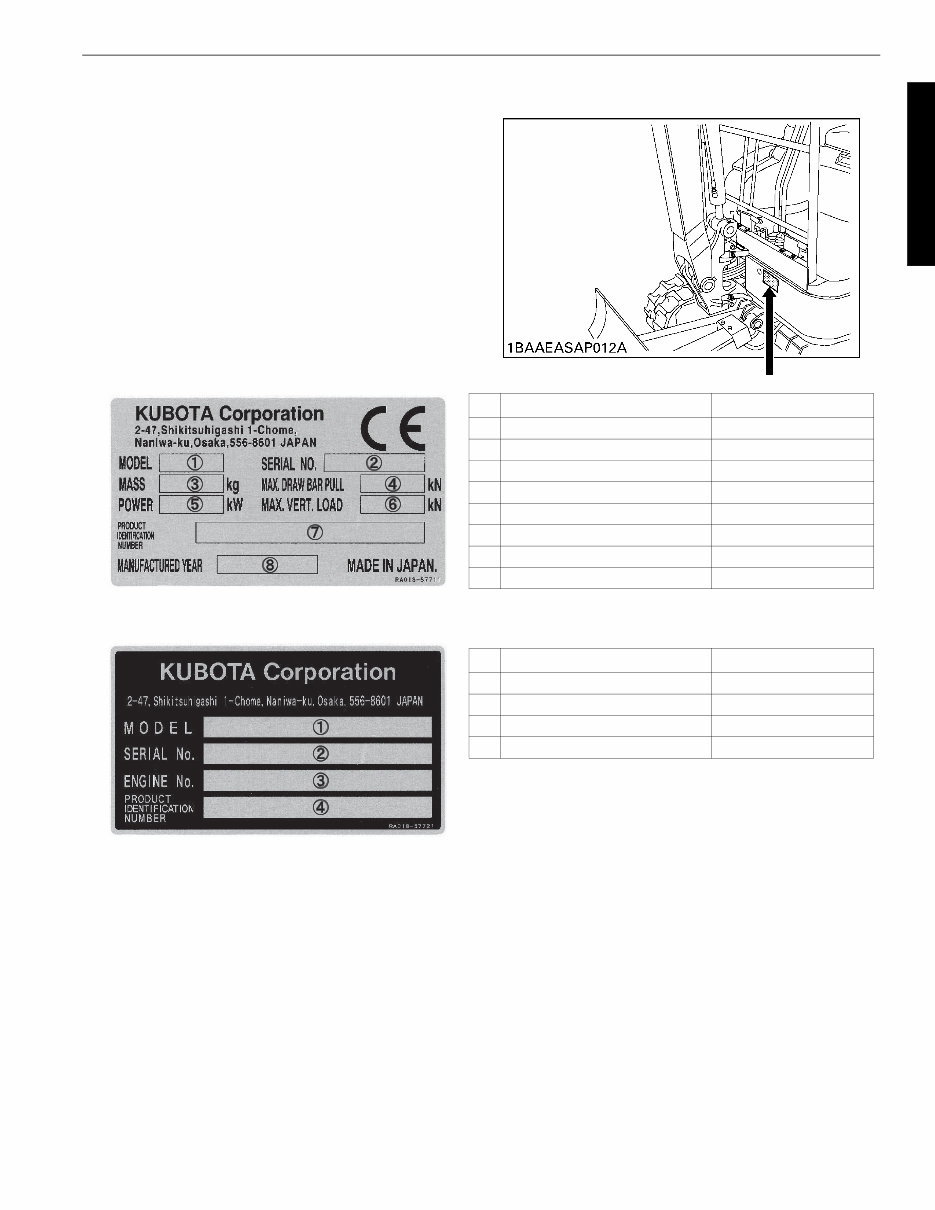
I-S-3 WSM U17-3α/U17-3/U17 I. GENERAL A. BODY AND ENGINE IDENTIFICATION MARKS If trouble occurs during use, or servicing is necessary, contact your dealer. Pass on your machine model, engine type and serial number to them. Name plate: Code No. RA018-57721 EU-version Example: S/N 10001 No. Items Contents 1 MODEL U17-3α 2 SERIAL No. 10001 3 MASS 1650 4 MAX, DRAW BAR PULL 32.3 5 POWER 11.6 6 MAX,VERT,LOAD 2.7 7 PRODUCT IDENTIFICATION NUMBER >JKUU0173*01S10001< 8 MANUFACTURED YEAR 2008 No. Items Contents 1 Machine model U17-3α 2 Serial No. 10001 3 Engine No. 4 PRODUCT IDENTIFICATION No. >JKUU0173*01S10001<
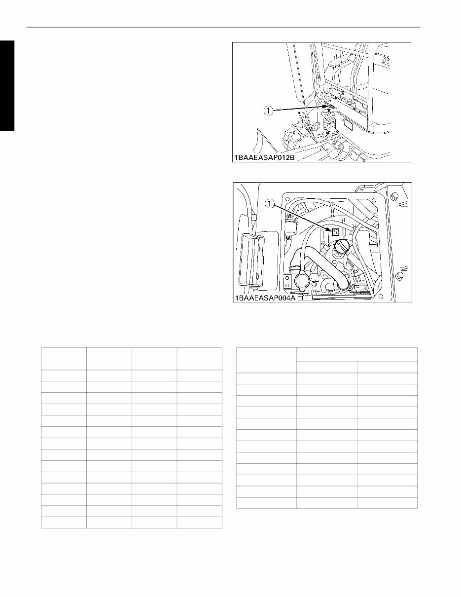
I-S-4 WSM U17-3α/U17-3/U17 I. GENERAL (1) Machine serial number (2) Engine serial number The engine serial number is an identified number for the engine. It is marked after the engine model number. It indicates month and year of manufacture as fol- lows. e.g. D902-8L001 “8” indicates year of 2008 and “L” indicates June. So, 8L indicates that the engine was manufactured in June 2008. (1) Serial No. (1) Engine serial No. Year of manufacture A: Engine Model Name and Serial Number Alphabet or Number Year Alphabet or Number Year 1 2001 F 2015 2 2002 G 2016 3 2003 H 2017 4 2004 J 2018 5 2005 K 2019 6 2006 L 2020 7 2007 M 2021 8 2008 N 2022 9 2009 P 2023 A 2010 R 2024 B 2011 S 2025 C 2012 T 2026 D 2013 V 2027 E 2014 Month of manufacture Month Engine Serial Number 0001 ~ 9999 10000 ~ January A0001 ~ A9999 B10000 ~ February C0001 ~ C9999 D10000 ~ March E0001 ~ E9999 F10000 ~ April G0001 ~ G9999 H10000 ~ May J0001 ~ J9999 K10000 ~ June L0001 ~ L9999 M10000 ~ July N0001 ~ N9999 P10000 ~ August Q0001 ~ Q9999 R10000 ~ September S0001 ~ S9999 T10000 ~ October U0001 ~ U9999 V10000 ~ November W0001 ~ W9999 X10000 ~ December Y0001 ~ Y9999 Z10000 ~
I-S-5 WSM U17-3α/U17-3/U17 I. GENERAL B. SAFETY PRECAUTIONS FOR SERVICING, DISASSEMBLY AND REASSEMBLY Safety precautions for servicing Most accidents during servicing arise from carelessness. Please remember that safety involves both the welfare of the employees and improved work efficiency. Safety precautions for disassembly and reassembly Machines must be disassembled and assembled efficiently and safely. It is very important to thoroughly understand the construction and function of the machine, to make all appro- priate preparations, and start operations according to the specified working procedures. a. Safety Measures Before Starting Work (1)Work clothes 1. Wear specified work cap and clothed. (Under no circumstances may workers wear undershirts only.) Cuffs must be kept buttoned, and any tears must be mended.) 2. Wear safety shoes. 3. Do not wear cotton gloves when working on the internal section of engine, reduction gears or hydraulic units for repair or others, or when using a hammer. Wear leather gloves, however, when hoisting wires. (2) Inspecting equipment and tools 1. Prepare equipment (cranes, fork lifts, tool, etc.) required for servicing and inspect for any problems before starting work. 2. Hammer heads (metal parts) must be firmly secured to their handles. 3. Check hosting tools (wire ropes, hoisting chains, etc.) before use. (3) Set workshop in order 1. Secure appropriate space needed for disas- sembly. 2. Secure a clean, safe place for arranging dis- assembled parts. 3. Store volatile substances (gasoline, light oil, thinner, oily articles, etc.) in appropriate containers at selected locations to prevent fire hazards. b. Safety Measures During Work (1) Protectors 1. Wear goggles when using chisels for chip- ping. 2. Use appropriate protectors during welding. 3. Wear a helmet when working with a crane or at elevated locations. (2)Team work 1. When working with two or more people, divide the work and maintain close commu- nication. 2. Crane work must be carried out using pre- determined signals. (3) Disassembly and assembly 1. Do not wear gloves when using hammers. 2. Use rods of the specified soft material for removing pins. Do not use a hammer as a pad. 3. Do not place fingers in holes when center- ing. 4. Heavy parts must be adequately supported before removing bolts. (4)Cranes 1. Basically, use a crane for objects heavier than 44lb (20kg). 2. Crane operation and hoisting must be per- formed only by qualified personnel. 3. Pay careful attention to the center of gravity when hoisting, and do not stand under the lifted objects. (5)Others 1. To work under a jacked-up carrier, be sure to place wood pieces underneath. 2. When charging batteries, make sure there are no open flames in the immediate vicin- ity. 3. All electric tools must be grounded. 4. Before welding the machine, remove the battery. • When removing the battery, be sure to disconnect negative (-) cord first. • When mounting the battery, be sure to connect the positive (+) cord first.
I-S-6 WSM U17-3α/U17-3/U17 I. GENERAL c. Preparation for Disassembly (1)Cleaning Remove mud and dirt from the body before disassembly. (2)Acceptance inspection The machine must be checked before it is disassembled to record existing conditions, such as those listed below. Model, serial number, and hourmeter reading • Reason for repair and repair history • Element stains • Fuel and oil condition • Parts damage *(Take photographs if necessary.) (3) Equipment and tools Prepare equipment, tools, cranes and parts storage racks as required. d. Precautions for Disassembly and Reassembly (1)Disassembly 1. Follow the specified disassembly procedures. 2. Make alignment marks to insure correct reassembly. 3. Arrange disassembled parts in an orderly way, and attach identification tags or put marks if needed. (2) Reassembly 1. Clean all parts before assembly. Repair any scratches or dents. Take special precautions against dirt and dust. 2. Parts with rust-preventive coatings must be assembles only after removing the coating. 3. Separated parts must be correctly reassembled using alignment marks. 4. As a rule, use a press to reassembled bearings, bushing and oil seals. Use pads when using a ham- mer. e. Maintenance CAUTION When adding oil and servicing: 1. Park the machine on a large, flat place. 2. Place the bucket and dozer on the ground. 3. Stop the engine 4. Move the attachment control lever and dozer lever to make sure the remaining pressure is relieved. 5. Draw out the starter key and check around the machine for safety. Before starting the job, carefully read the Operational Manual in " ! Servicing Precautions" on the yellow pages. f. Waste Disposal WARNING Do not carelessly throw away and burn waste materials. Such actions may lead to environmental pollu- tion and punishment by local laws. When disposing of waste: * Let out waste fluid from the machine into a container. * Do not let waste fluid flow on the ground as well as into a river, lake, marsh, and sea. * Contact your dealer or a qualified industrial waste handler to treat (dispose of or incinerate) harmful waste materials. Those materials include waste oil, fuel, cooling water (anti-freeze), coolant, solvent, filters, batteries, rubber and other toxic substances.
Kubota U17-3α, U17-3, U17 Mini Excavator Service & Repair Manual
Models Covered:
Kubota U17-3α (EU Version)
Kubota U17-3 (KTC, KCL Versions)
Kubota U17 (KTA Version)
Engine Covered:
Kubota D902
The Kubota U17-3α, U17-3, U17 Mini Excavator Service & Repair Manual provides comprehensive OEM guidance for the inspection, maintenance, and servicing of these compact excavators. It includes full mechanical and hydraulic systems data, as well as electrical schematics and torque specifications essential for professional service technicians and experienced operators.
This manual applies to both EU and non-EU versions, with region-specific updates and procedures. From standard maintenance tasks to component-level teardown, it’s a detailed resource engineered to support safe and accurate repairs, all while complying with Kubota’s critical safety protocols and inspection standards.
Critical Functions: Travel motor setup, swing motor installation, pump coupling, torque tables
Maintenance Schedules: Daily, periodic, and conditional maintenance for different regional versions (EU/KTC/KTA)
Whether you operate in the field or the workshop, this manual is a trusted Kubota resource for keeping your U17-series excavator running reliably and safely.
Printable: Yes Language: English Compatibility: Works on all modern devices (Windows, macOS, iOS, Android) Requirements: Any PDF reader (e.g., Adobe Reader)
Recently Viewed
5,521,897Happy Clients
2,594,462eManuals
1,120,453Trusted Sellers
15Years in Business
Price:
Actual Price:
Kubota U17-3α, U17-3, U17 Mini Excavator Service & Repair Manual