Kubota Kx71-3 Excavator Service Repair Workshop Manual
What's Included?
Lifetime Access
Fast Download Speeds
Online & Offline Access
Access PDF Contents & Bookmarks
Full Search Facility
Print one or all pages of your manual
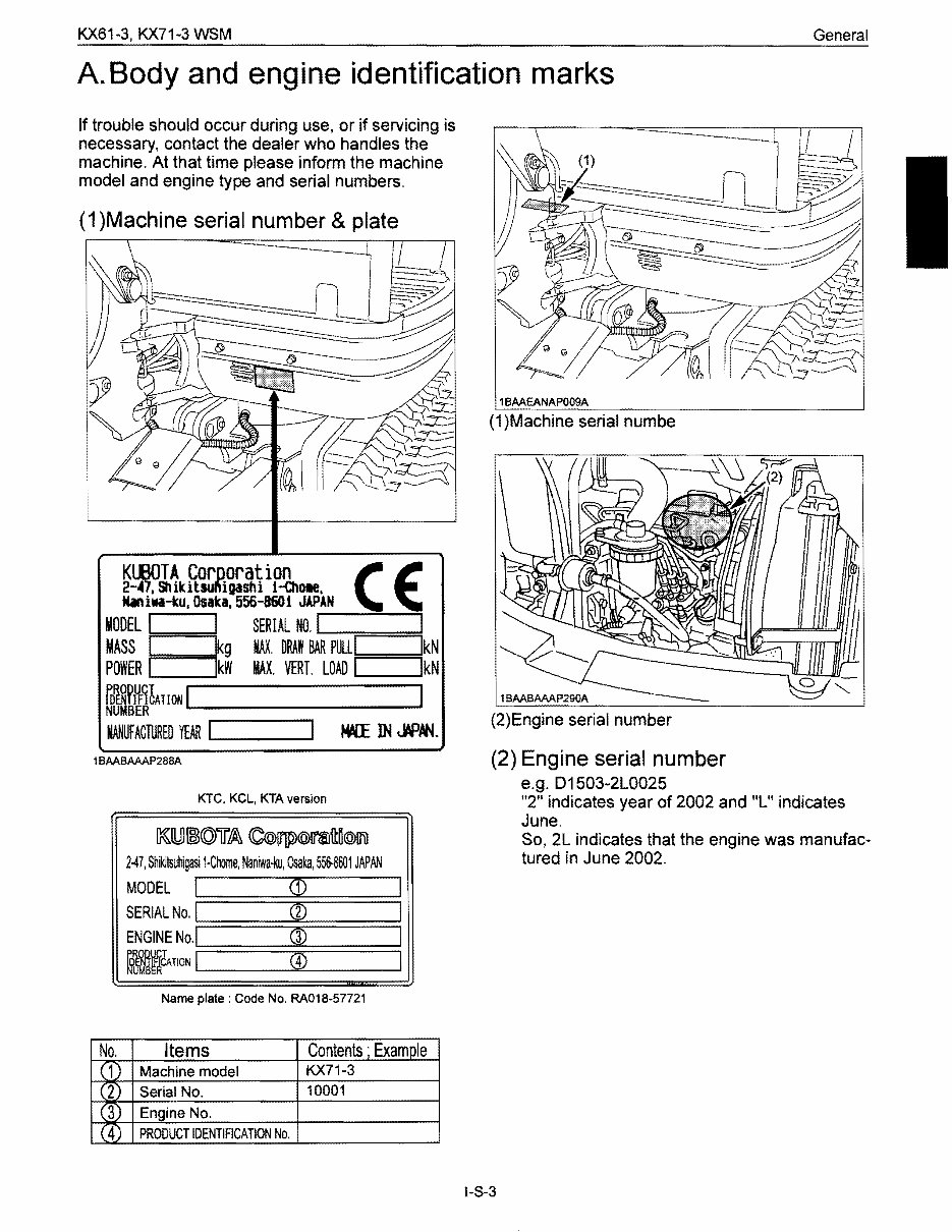
KX61-3, KX71-3 WSM General A. Body and engine identification marks If trouble should occur during use, or if servicing is necessary, contact the dealer who handles the machine. At that time please inform the machine model and engine type and serial numbers. (1 )Machine serial number & plate 2~7;ShikitlU"igashi l-Q\ote, KllBOTA Corooration ( E Niniwa-ku, Osaka. 556-8601 JAPAN MASS kg MAX. DRAW BAL...R-PUL"LI====::;lkN MODEL § SERIAL No.1 I POWER kW MAX. VERT. LOAD I IkN !ATIONI I MANUFACTURED YEAR L...I__----I 1BAABAAAP288A KTC. KCL, KTA version ~lUl~(Q)ii£6\ <C®~@l1'!lft~@1l1l 247, Shi~tsuhigasi 1·Chome, Naniwa-ku, Osaka,556-8601 JAPAN Name plate: Code No. RA018-57721 1 BAAEANAP009A (1)Machine serial numbe (2)Engine serial number (2) Engine serial number e.g. D1503-2L0025 "2" indicates year of 2002 and "L" indicates June. So, 2L indicates that the engine was manufac- tured in June 2002. No. Items Contents· Example ( 1 Machine model KX71-3 ( 2) Serial No. 10001 (3 Engine No. (4 PRODUCT IDENTIFICATION No. I-S-3
KX71-3 WSM General B. Safety precautions for servicing, disassembly and reassembly A Safety precautions for servicing Most accidents during servicing arise from carelessness. Please remember that Safety involves both the welfare of the employees and improved work efficiency. A Safety precautions for Disassembly and reassembly Machines must be disassembled and assembled effiCiently and safely. It is very important to thoroughly understand the construction and function of the machine, to make all appropriate preparations, and start operations according to the specified working procedures. a. Safety measures before starting work (1 ) Work clothes 1. Wear specified work cap and clothed. (Under no circumstances may workers wear undershirts only.) Cuffs must be kept buttoned, and any tears must be mended.) 2. Wear safety shoes. 3. Do not wear cotton gloves when working on the internal section of engine, reduction gears or hydrauric units for repair or others, or when using a hammer. Wear leather gloves, however, when hoisting wires. (2) Inspecting equipment and tools 1. Prepare equipment (cranes, fork lifts, tool, etc.) required for servicing and inspect for any problems before starting work. 2. Hammer heads (metal parts) must be firmly secured to their handles. 3. Check hosting tools (wire ropes, hOisting chains, etc.) before use. (3) Keep workshop in order 1. Secure appropriate space needed for disassembly to the job. 2. Secure a clean, safe place for arranging disassembled parts. 3. Store volatile substances (gasoline, light oil, thinner, oily articles, etc.) in appropriate containers at selected locations to prevent fire hazards. b. Safety measures during work (1) Protectors 1. Wear goggles when using chisels for chipping. 2. Use appropriate protectors during welding. 3. Wear a helmet when working with a crane or at elevated locations. (2) Team work 1. When working with two or more people, divide the work and maintain close communication. 2. Crane work must be carried out using predetermined signals. (3) Disassembly and assembly 1. Do not wear gloves when using hammers. 2. Use rods of the speCified soft material for removing pins. Do not use a hammer as a pad. 3. Do not place fingers in holes when centering. 4. Heavy parts must be adequately supported before removing bolts. (4) Cranes 1. In principle, use a crane for objects heavier than 44lb (20kg). 2. Crane operation and hOisting must be performed only by qualified personal. 3. Pay careful attention to the center of gravity when hOisting, and do not stand under the lifted objects. (5) Others 1. To work under a jacked-up carrier, be sure to place wood pieces under it. 2. When charging batteries, make sure there are no open flames in the immediate vicinity. 3. All electric tools must be grounded. 4. Before welding the machine, remove the battery. • When removing the battery, be sure to disconnect negative (-) cord first. • When mounting the battery, be sure to connect the positive (+) cord first. I-S-4
KX61-3, KX71-3 W5M General c. Preparation for disassembly (1) Cleaning Remove mud and dirt from the body before disassembly. (2) Acceptance inspection The machine must be checked before it is disassembled to record existing conditions, such as those listed below. Model, serial number, and hourmeter reading • Reason for repair and repair history • Element stains • Fuel and oil condition • Parts damage *(Take photographs if necessary.) (3) Equipment and tools prepare equipment, tools, cranes and parts storage racks as required. d. Precautions for disassembly and reassembly (1) Disassembly 1. Follow the specified disassembly procedures. 2. Make alignment marks to insure correct reassembly. 3. Arrange disassembled parts in an orderly way, and attach identification tags or put marks if needed. (2) Reassembly 1. Clean all parts before assembly. Repair any scratches or dents. Take special precautions against dirt and dust. 2. Parts with rust-preventive coatings must be assembles only after removing the coating. 3. Separated parts must be correctly reassembled using alignment marks. 4. As a rule, use a press to reassembled bearings, bushing and oil seals. Use pads when using a hammer. 1-5-5
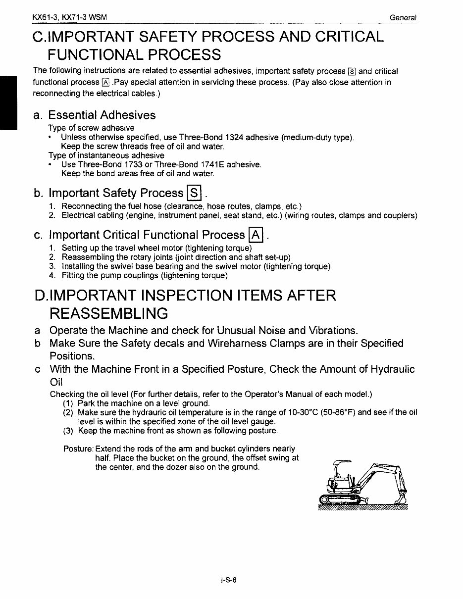
KX61-3, KX71-3 WSM General C.IMPORTANT SAFETY PROCESS AND CRITICAL FUNCTIONAL PROCESS The following instructions are related to essential adhesives, important safety process I]] and critical functional process ~ .Pay special attention in servicing these process. (Pay also close attention in reconnecting the electrical cables.) a. Essential Adhesives Type of screw adhesive • Unless otherwise specified, use Three-Bond 1324 adhesive (medium-duty type). Keep the screw threads free of oil and water. Type of instantaneous adhesive • Use Three-Bond 1733 or Three-Bond 1741 E adhesive. Keep the bond areas free of oil and water. b. Important Safety Process ~ . 1. Reconnecting the fuel hose (clearance, hose routes, clamps, etc.) 2. Electrical cabling (engine, instrument panel, seat stand, etc.) (wiring routes, clamps and couplers) c. Important Critical Functional Process ~ . 1. Setting up the travel wheel motor (tightening torque) 2. Reassembling the rotary jOints Goint direction and shaft set-up) 3. Installing the swivel base bearing and the swivel motor (tightening torque) 4. Fitting the pump couplings (tightening torque) D.IMPORTANT INSPECTION ITEMS AFTER REASSEMBLING a Operate the Machine and check for Unusual Noise and Vibrations. b Make Sure the Safety decals and Wireharness Clamps are in their Specified Positions. c With the Machine Front in a Specified Posture, Check the Amount of Hydraulic Oil Checking the oil level (For further details, refer to the Operator's Manual of each model.) (1) Park the machine on a level ground. (2) Make sure the hydrauric oil temperature is in the range of 10-30°C (50-86°F) and see if the oil level is within the specified zone of the oil level gauge. (3) Keep the machine front as shown as following posture. Posture: Extend the rods of the arm and bucket cylinders nearly half. Place the bucket on the ground, the offset swing at the center, and the dozer also on the ground. 1-8-6
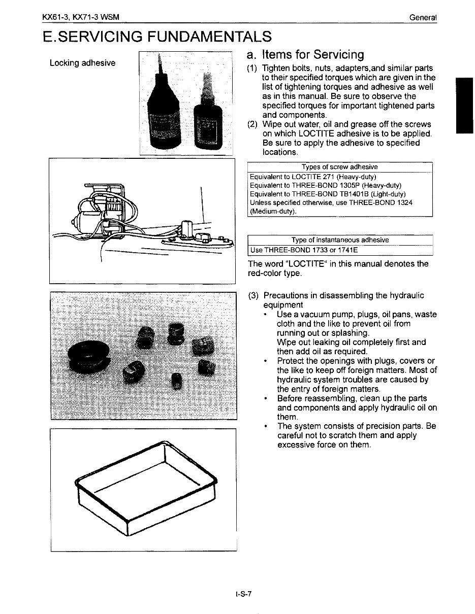
KX61-3, KX71-3 WSM General E.SERVICING FUNDAMENTALS a. Items for Servicing Locking adhesive (1) Tighten bolts, nuts, adapters,and similar parts to their specified torques which are given in the list of tightening torques and adhesive as well as in this manual. Be sure to observe the specified torques for important tightened parts and components. (2) Wipe out water, oil and grease off the screws on which LOCTITE adhesive is to be applied. Be sure to apply the adhesive to specified locations. Types of screw adhesive Equivalent to LOCTITE 271 (Heavy-duty) Equivalent to THREE-BOND 1305P (Heavy-duty) Equivalent to THREE-BOND TB1401 B (Light-duty) Unless specified otherwise, use THREE-BOND 1324 (Medium-duty). Type of instantaneous adhesive Use THREE-BOND 1733 or 1741E The word "LOCTITE" in this manual denotes the red-color type. (3) Precautions in disassembling the hydraulic equipment • Use a vacuum pump, plugs, oil pans, waste cloth and the like to prevent oil from running out or splashing. Wipe out leaking oil completely first and then add oil as required. • Protect the openings with plugs, covers or the like to keep off foreign matters. Most of hydraulic system troubles are caused by the entry of foreign matters. • Before reassembling, clean up the parts and components and apply hydraulic oil on them. • The system consists of precision parts. Be careful not to scratch them and apply excessive force on them. I-S-7
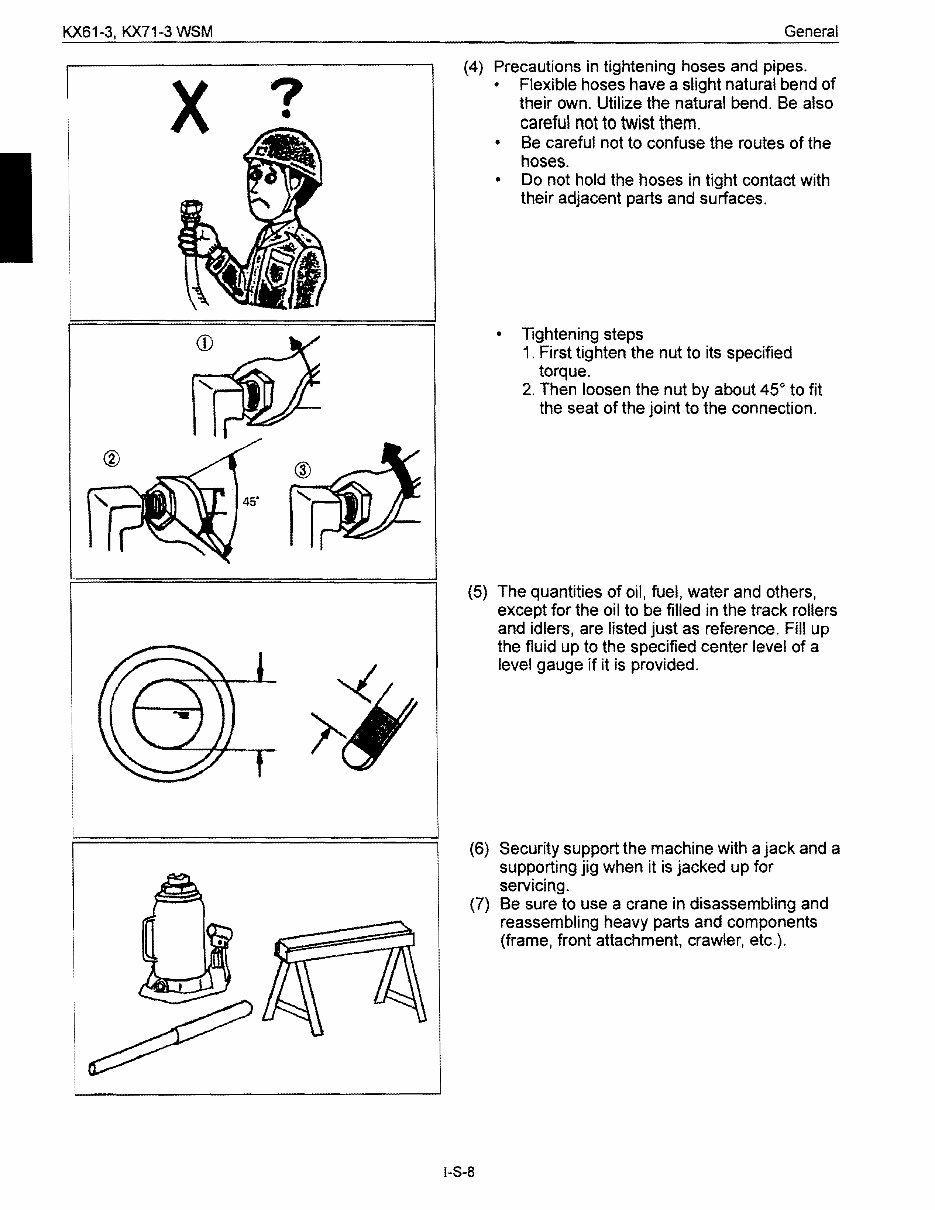
KX61-3, KX71-3 WSM General x ? • (4) Precautions in tightening hoses and pipes. • Flexible hoses have a slight natural bend of their own. Utilize the natural bend. Be also careful not to twist them. • Be careful not to confuse the routes of the hoses. • Do not hold the hoses in tight contact with their adjacent parts and surfaces. • Tightening steps 1. First tighten the nut to its specified torque. 2. Then loosen the nut by about 45 0 to fit the seat of the joint to the connection. (5) The quantities of oil, fuel, water and others, except for the oil to be filled in the track rollers and idlers, are listed just as reference. Fill up the fluid up to the specified center level of a level gauge if it is provided. (6) Security support the machine with a jack and a supporting jig when it is jacked up for servicing. (7) Be sure to use a crane in disassembling and reassembling heavy parts and components (frame, front attachment, crawler, etc.). 1-8-8
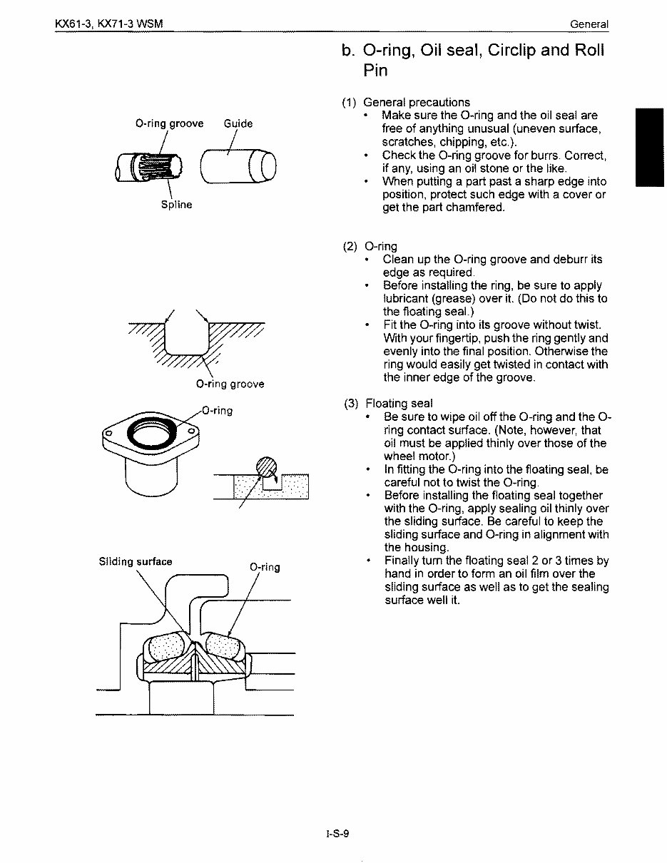
KX61-3, KX71-3 WSM General b. O-ring, Oil seal, Circlip and Roll Pin (1) General precautions Make sure the O-ring and the oil seal are O-ring groov~ free of anything unusual (uneven surface, scratches, chipping, etc.). • Check the O-ring groove for burrs. Correct, if any, using an oil stone or the like. • When putting a part past a sharp edge into position, protect such edge with a cover or Spline get the part chamfered. (2) O-ring • Clean up the O-ring groove and deburr its edge as required. Before installing the ring, be sure to apply lubricant (grease) over it. (Do not do this to the floating seaL) • Fit the O-ring into its groove without twist. With your fingertip, push the ring gently and evenly into the final position. Otherwise the ring would easily get twisted in contact with the inner edge of the groove. O-ring groove (3) Floating seal • Be sure to wipe oil off the O-ring and the 0- ring contact surface. (Note, however, that oil must be applied thinly over those of the wheel motor.) • In fitting the O-ring into the floating seal, be careful not to twist the O-ring. Before installing the floating seal together with the O-ring, apply sealing oil thinly over the sliding surface. Be careful to keep the sliding surface and O-ring in alignment with the housing. Sliding surface • Finally tum the floating seal 2 or 3 times by O-ring hand in order to form an oil film over the sliding surface as well as to get the sealing surface well it. O-ring I-S-9
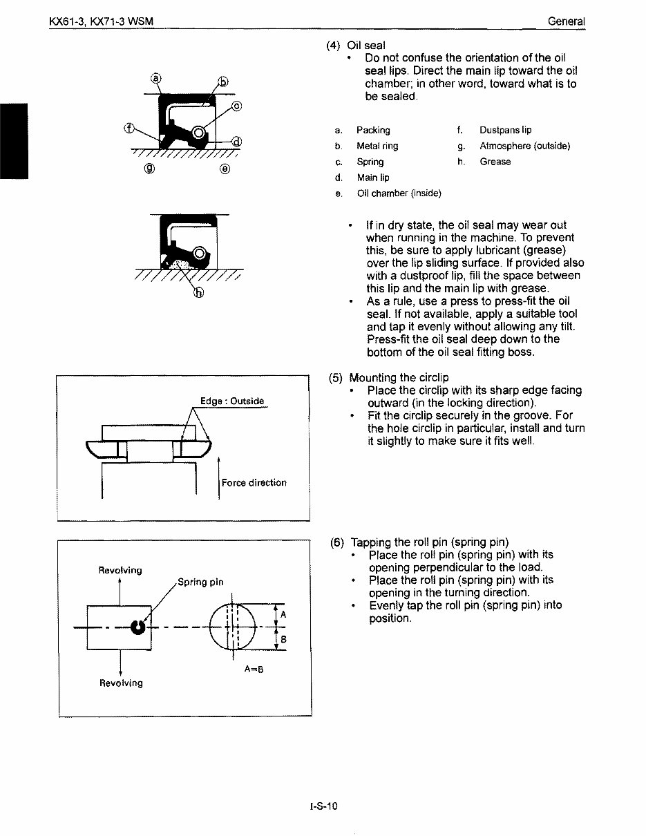
KX61-3. KX71-3 WSM General (4) Oil seal • Do not confuse the orientation of the oil seal lips. Direct the main lip toward the oil chamber; in other word, toward what is to be sealed. a. Packing f. Dustpans lip b. Metal ring g. Atmosphere (outside) c. Spring h. Grease d. Main lip e. Oil chamber (inside) • If in dry state. the oil seal may wear out when running in the machine. To prevent this. be sure to apply lubricant (grease) over the lip sliding surface. If provided also with a dustproof lip. fill the space between this lip and the main lip with grease. • As a rule, use a press to press-fit the oil seal. If not available, apply a suitable tool and tap it evenly without allowing any tilt. Press-fit the oil seal deep down to the bottom of the oil seal fitting boss. (5) Mounting the circlip • Place the circlip with its sharp edge facing outward (in the locking direction). • Fit the circlip securely in the groove. For the hole circlip in particular, install and turn it slightly to make sure it fits well. ® Edge: Outside (6) Tapping the roll pin (spring pin) • Place the roll pin (spring pin) with its opening perpendicular to the load. • Place the roll pin (spring pin) with its opening in the turning direction. • Evenly tap the roll pin (spring pin) into position. Revolving Spring pin A B A=8 Revolving 1-8-10
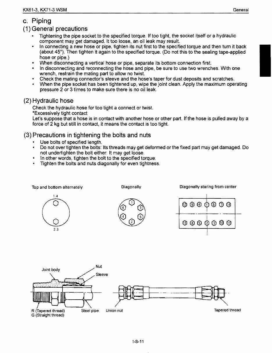
KX61-3, KX71-3 WSM General c. Piping (1) General precautions • Tightening the pipe socket to the specified torque. If too tight, the socket itself or a hydraulic component may get damaged. It too loose, an oil leak may result. • In connecting a new hose or pipe, tighten its nut first to the specified torque and then turn it back (about 45°). Then tighten it again to the specified torque. (Do not this to the sealing tape-applied hose or pipe.) • When disconnecting a vertical hose or pipe, separate its bottom connection first. • In disconnecting and reconnecting the hose and pipe, be sure to use two wrenches. With one wrench, restrain the mating part to allow no twist • Check the mating connector's sleeve and the hose's taper for dust deposits and scratches. • When the pipe socket has been tightened up, wipe the joint clean. Apply the maximum operating pressure 2 or 3 times to make sure there is no oil leak. (2) Hydraulic hose Check the hydraulic hose for too tight a connect or twist. *Excessively tight contact Let's suppose that a hose is in contact with another hose or other part. If the hose is pulled away by a force of 2 kg but still in contact, it means the contact is too tight. (3) Precautions in tightening the bolts and nuts • Use bolts of specified length. • Do not over tighten the bolts: Its threads may get deformed or the fixed part may get damaged. Do not undertighten the bolt either: It may get loose. • In other words, tighten the bolt to the specified torque. • Tighten the bolts and nuts diagonally for even tightness. Top and bottom alternately Diagonally Diagonally staring from center 1.4 2.3 Nut Sleeve R (Tapered thread) Steel pipe Union nut Tapered thread G (Straight thread) I-S-11
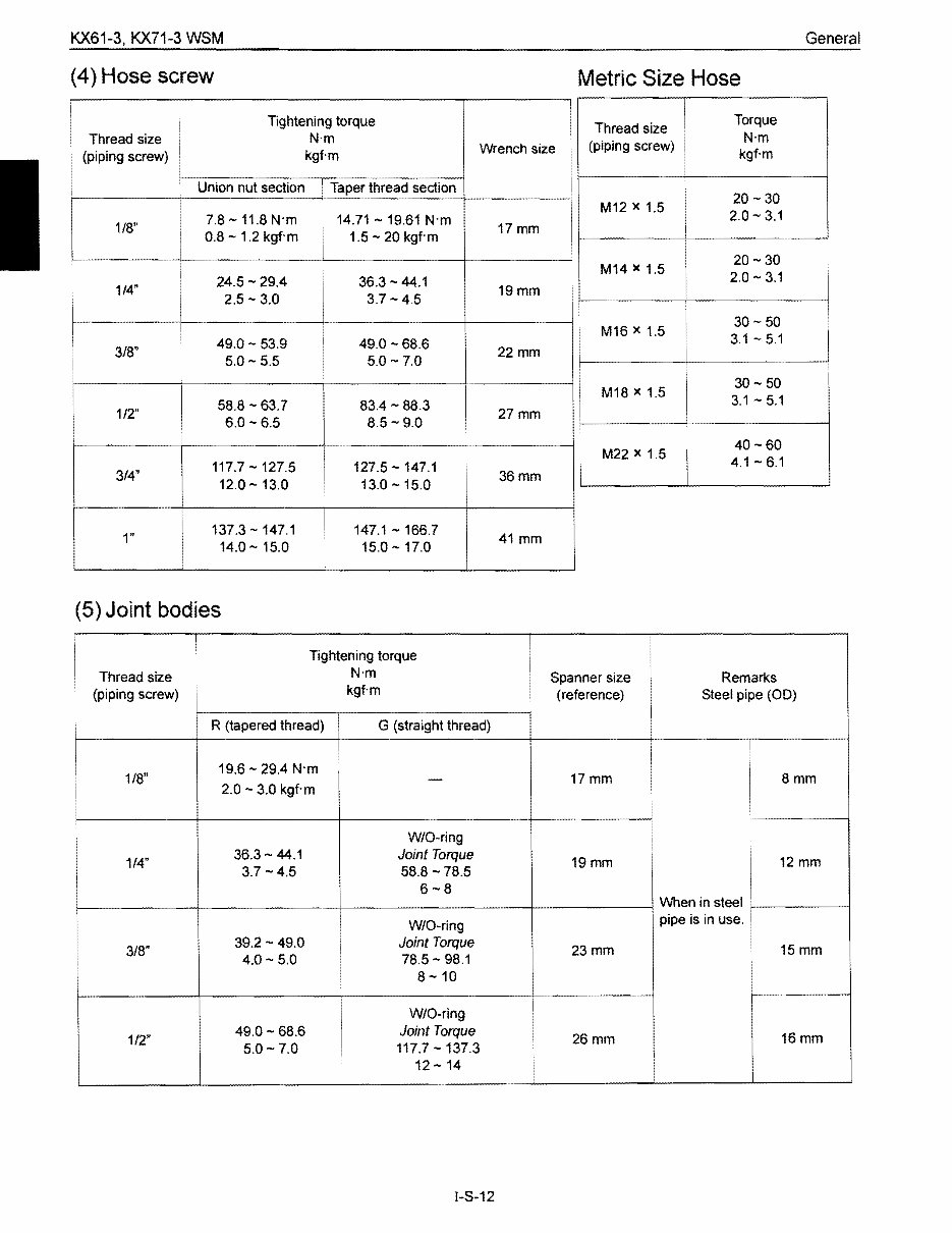
KX61-3, KX71-3 WSM General (4) Hose screw Metric Size Hose ! i I Torque Tightening torque 1 Thread size N'm Thread size N'm (piping screw) Wrench size 1 kgf·m kgf-m (piping screw) i 1 Union nut section . Taper thread section I 20 - 30 M12)( 1.5 2.0 - 3.1 7.8 -11.8 N'm 14.71 - 19.61 N'm 1/8" 17mm i ..- 0.8 - 1.2 kgf'm 1.5 - 20 kgf'm i I 20-30 1 M14)( 1.5 1 2.0 - 3.1 i 24.5 - 29.4 36.3 - 44.1 1 1/4" 19mm 3.7- 4.5 .. 2.5 - 3.0 30- 50 M16)( 1.5 3.1 - 5.1 49.0 -68.6 49.0 - 53.9 3/8" 22mm i 1 i 5.0 - 5.5 5.0 - 7.0 1 i 30- 50 M18)( 1.5 3.1 - 5.1 58.8 - 63.7 83.4 - 88.3 I 1/2" 27mm I ... 6.0 - 6.5 8.5 - 9.0 : i i 40 -60 : M22)( 1.5 4.1 - 6.1 117.7 - 127.5 127.5 -147.1 3/4" 36mm I I 13.0 -15.0 12.0 - 13.0 137.3 - 147.1 147.1 -166.7 I 1" 41 mm 14.0 - 15.0 15.0 -17.0 i (5) Joint bodies I 1 Tightening torque N'm i Thread size Spanner size Remarks kgf'm (piping screw) (reference) Steel pipe (00) i I 1 R (tapered thread) G (straight thread) 1 ! 1 19.6 - 29.4 N'm 1/8" 17mm 8mm - 2.0 - 3.0 kgf'm i W/O-ring 1 Joint Torque 36.3 - 44.1 1/4" 12 mm 19mm 3.7 -4.5 58.8 -78.5 6-8 When in steel pipe is in use. i W/O-ring 39.2 - 49.0 Joint Torque 3/8" 15mm 23mm 4.0 - 5.0 78.5 - 98.1 8-10 W/O-ring Joint Torque 49.0 - 68.6 16mm 1/2" 26mm 117.7 - 137.3 12 - 14 5.0 - 7.0 1 1-8-12
This is the Kubota Kx71-3 Excavator Service Repair Workshop Manual. It contains comprehensive service and repair instructions used by mechanics worldwide.
All major topics are covered, including step-by-step instructions, diagrams, illustrations, wiring schematics, and specifications for repairing and troubleshooting your Kubota Kx71-3 Excavator.
The manual is divided into three parts: General, Mechanism, and Servicing for each section.
Kubota Kx71-3 Excavator General: Includes tractor identification, general precautions, maintenance checklist, check and maintenance, and special tools.
Kubota Kx71-3 Excavator Mechanism: Provides information on construction and function, essential for troubleshooting, disassembling, and servicing.
Kubota Kx71-3 Excavator Servicing: Covers troubleshooting, servicing specifications, tightening torque, checking and adjusting, disassembling and assembling, procedures, precautions, factory specifications, and allowable limits.
This manual is useful for both professional mechanics and DIY enthusiasts. It includes the same specifications and procedures available to an authorized dealer service department. Even car owners with basic mechanical skills can benefit from owning and referring to this manual, enabling them to be better informed and discuss repairs more knowledgeably with an automotive technician.
Accurate, clear, and concise text, combined with illustrations, makes it possible for anyone with even basic mechanical knowledge to safely and easily service and repair their vehicle.
The Kubota Kx71-3 Excavator Service Repair Workshop Manual is available in .PDF format, viewable on PC, Mac, and various devices, including many phones and e-readers. It is printable, allowing for easy access to individual pages as needed.
Compatible with all versions of Windows and Mac, this manual is a valuable resource for anyone looking to save money by performing simple repairs themselves.
It covers a wide range of topics including lubrication and maintenance, suspension, differential and driveline, brakes, cooling, electronic control modules, engine systems, fuel system, steering, heating and air conditioning, emissions control, and much more.
All pages are printable, making it convenient to take the manual into the garage or workshop, ultimately saving money by doing your own repairs.
With very easy to follow, step-by-step instructions, this manual is suitable for any skill level, making it an essential resource for maintaining and repairing the Kubota Kx71-3 Excavator.
Recently Viewed
5,521,897Happy Clients
2,594,462eManuals
1,120,453Trusted Sellers
15Years in Business
Price:
Actual Price:
Kubota Kx71-3 Excavator Service Repair Workshop Manual