00-2 PC400/450(LC)-7 (1) CONTENTS No. of page 01 GENERAL ............................................................................................................................ 01-1 10 STRUCTURE, FUNCTION AND MAINTENANCE STANDARD............................................ 10-1 20 TESTING AND ADJUSTING ............................................. To be issued next time 30 DISASSEMBLY AND ASSEMBLY ......................... To be issued next time 90 OTHERS ................................................................................................................................ 90-1
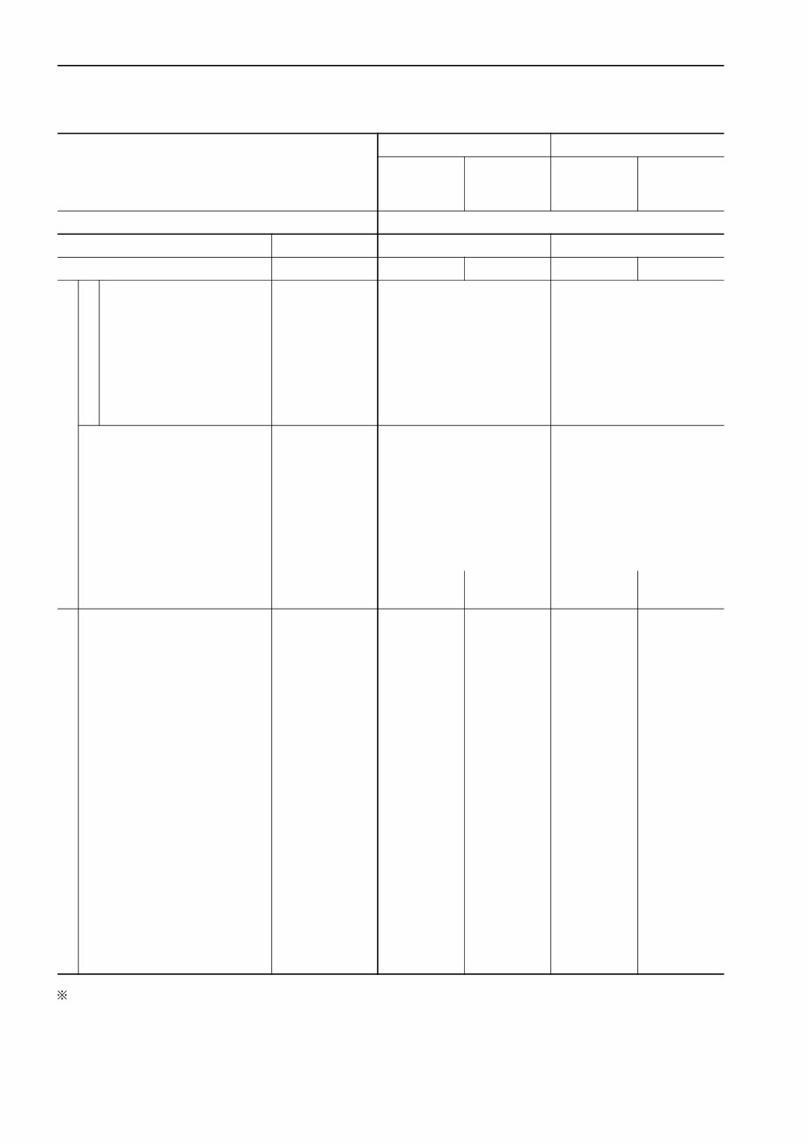
01-2 PC400/450(LC)-7 GENERAL SPECIFICATION DRAWINGS SPECIFICATION DRAWINGS DIMENSIONS WORKING RANGES
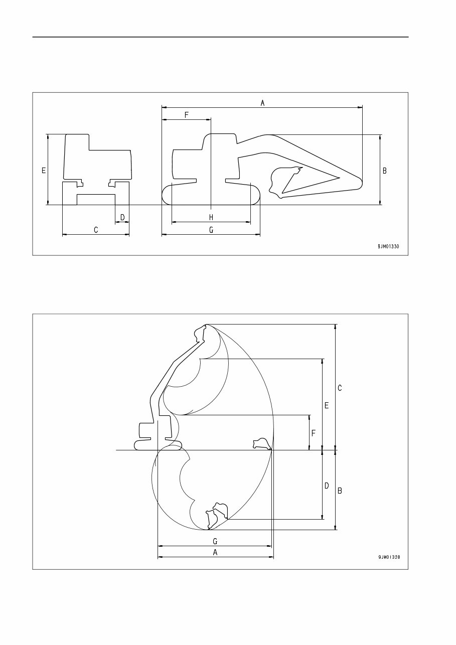
PC400/450(LC)-7 01-3 GENERAL SPECIFICATION DRAWINGS DIMENSIONS Fixed gauge specification Variable gauge specification WORKING RANGES Item Unit PC400-7 PC400LC-7 PC450-7 PC450LC-7 A Overall length mm 11,940 11,940 12,040 12,040 B Overall height mm 3,635 3,635 3,660 3,660 C Overall width mm 3,340 3,440 3,340 3,340 D Track shoe width mm 600 700 600 600 E Height of machine cab mm 3,265 3,265 3,265 3,265 F Tail swing radius mm 3,645 3,645 3,645 3,645 G Track overall length mm 5,055 5,355 5,055 5,355 H Length of track on ground mm 4,020 4,350 4,020 4,350 Min. ground clearance mm 555 550 555 550 Item Unit PC400-7 PC400LC-7 PC450-7 PC450LC-7 A Overall length mm 11,940 11,940 12,040 12,040 B Overall height mm 3,635 3,635 3,660 3,660 C Overall width mm 3,490 3,490 3,490 3,490 D Track shoe width mm 600 600 600 600 E Height of machine cab mm 3,265 3,265 3,265 3,265 F Tail swing radius mm 3,645 3,645 3,645 3,645 G Track overall length mm 5,055 5,355 5,055 5,355 H Length of track on ground mm 4,020 4,350 4,020 4,350 Min. ground clearance mm 685 685 685 685 Working range Unit PC400-7 PC400LC-7 PC450-7 PC450LC-7 A Max. digging reach mm 12,025 12,025 12,005 12,005 B Max. digging depth mm 7,820 7,820 7,790 7,790 C Max. digging height mm 10,915 10,915 10,925 10,925 D Max. vertical wall depth mm 6,870 6,870 6,600 6,600 E Max. dumping height mm 7,565 7,565 7,625 7,625 F Min. dumping height mm — — — — G Max. reach at ground level mm 11,820 11,820 11,800 11,800
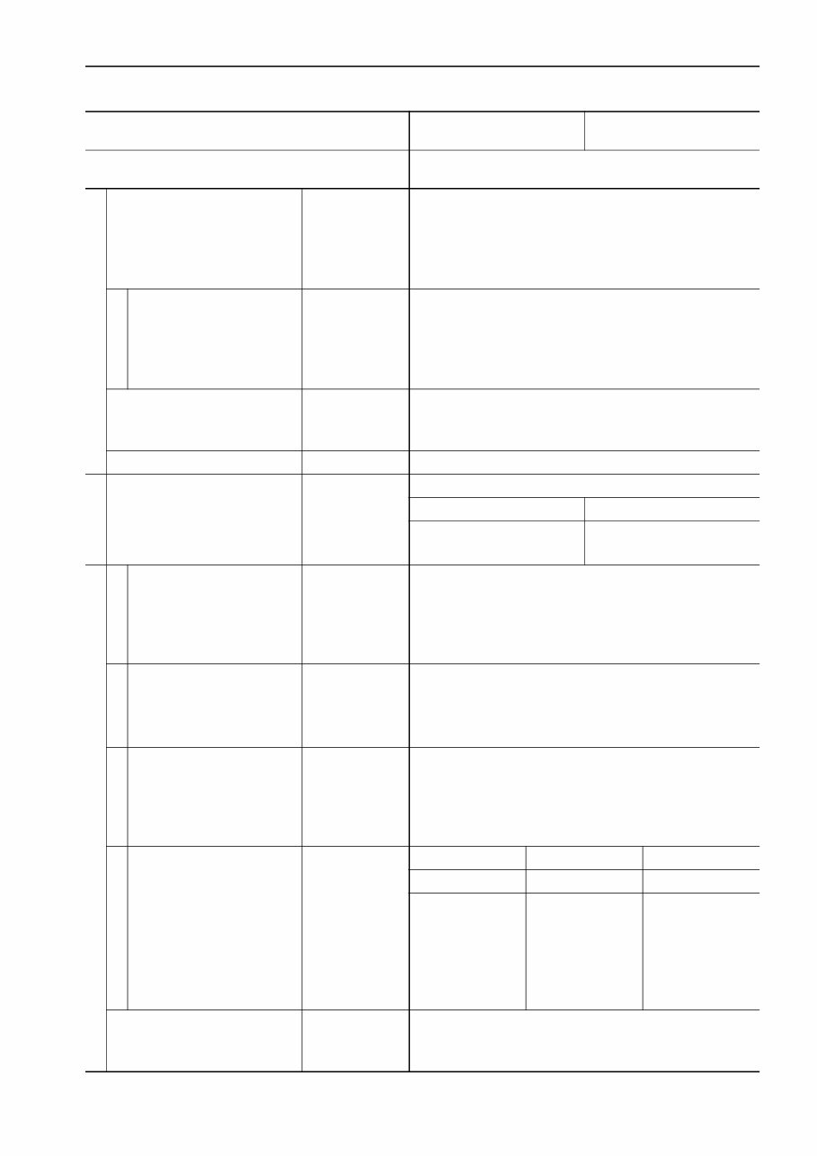
01-4 PC400/450(LC)-7 GENERAL SPECIFICATIONS SPECIFICATIONS PC400-7, PC400LC-7 : The “Mi” mode is on the multi-monitor specification machine only Machine model PC400-7 PC400LC-7 Fixed gauge spec. Variable gauge spec. Fixed gauge spec. Variable gauge spec. Serial Number 50001 and up Bucket capacity m 3 1.4 1.4 Weight of machine kg 41,200 42,400 42,200 43,500 Performance Working ranges Max. digging depth Max. vertical wall depth Max. digging reach Max. reach at ground level Max. digging height Max. dumping height mm mm mm mm mm mm 7,820 6,870 12,025 11,820 10,915 7,565 7,820 6,870 12,025 11,820 10,915 7,565 Max. digging force (using power max. function) Swing speed Swing max. slope angle Travel speed Gradeability kN {kg} kN {kg} rpm deg. km/h deg. 256.0 {26,100} (274.6 {28,000}) 9.1 20 Lo: 3.0, Mi: 4.4, Hi: 5.5 35 256.0 {26,100} (274.6 {28,000}) 9.1 20 Lo: 3.0, Mi: 4.4, Hi: 5.5 35 Ground pressure [standard shoe width] kPa {kg/cm 2 } [mm] 77.7{0.79} [600] 79.9 {0.82} [600] 73.9 {0.75} [700] 65.3 {0.67} [700] Dimensions Overall length (for transport) Overall width Overall width of track Overall width of track when extended Overall height (for transport) Overall height to top of machine Ground clearance of upper structure Min. ground clearance Tail swing radius Min. swing radius of work equipment Height of work equipment at min. swing radius Length of track on ground Track gauge Height of machine cab mm mm mm mm mm mm mm mm mm mm mm mm mm mm 11,940 3,340 3,340 — 3,635 3,265 1,320 555 3,645 4,735 9,210 4,020 2,740 3,265 11,940 3,490 2,990 3,490 3,635 3,265 1,320 685 3,645 4,735 9,210 4,020 2,890 3,265 11,940 3,440 3,440 — 3,635 3,265 1,320 555 3,645 4,735 9,210 4,020 2,740 3,265 11,940 3,490 2,990 3,490 3,635 3,265 1,320 685 3,645 4,735 9,210 4,020 2,890 3,265
PC400/450(LC)-7 01-5 GENERAL SPECIFICATIONS Machine model PC400-7 PC400LC-7 Serial Number 50001 and up Engine Model Type No. of cylinders – bore × stroke Piston displacement mm l {cc} SAA6D125E-3 4-cycle, water-cooled, in-line, vertical, direct injection, with turbocharger and aftercooler 6 – 125 × 150 11.045 {11,045} Performance Flywheel horsepower Max. torque Max. speed at no load Min. speed at no load Min. fuel consumption kW/rpm {HP/rpm} Nm/rpm {kgm/rpm} rpm rpm g/kWh {g/HPh} 246.4/1,850 {330/1,850} 1,334/1,400 {136/1,400} 1,930 1,000 203 {151} Starting motor Alternator Battery 24V, 7.5 kW 24V, 35A 12V, 110 Ah × 2 Radiator core type ALW-4 Undercarriage Carrier roller 2 on each side Track roller 7 on each side 8 on each side Track shoe Assembly-type triple grouser, 45 on each side Assembly-type triple grouser, 48 on each side Hydraulic system Hydraulic pump Type × No. Delivery Set pressure l /min MPa {kg/cm 2 } HPV190+190, variable displacement, piston type x2 345 × 2 37.8 {380} Control valve Type × No. Control method 6-spool type + 1-spool type × 1 Hydraulic Hydraulic motor Travel motor Swing motor KMV200ADT-2, Variable displacement, piston type (with brake valve, parking brake): × 2 KMF230ABE-5, Fixed displacement piston type (with safety valve, holding brake, reverse rotation preventive valve): × 1 Hydraulic cylinder Boom Arm Bucket Type Double-acting piston Double-acting piston Double-acting piston Inside diameter of cylinder mm 160 185 160 Diameter of piston rod mm 110 120 110 Stroke mm 1,570 1,820 1,270 Max. distance between pins mm 3,830 4,325 3,140 Min. distance between pins mm 2,260 2,505 1,870 Hydraulic tank Hydraulic filter Hydraulic cooler Closed box type Tank return side CF40-1 (Air cooled)
01-6 PC400/450(LC)-7 GENERAL SPECIFICATIONS PC450-7, PC450LC-7 : The “Mi” mode is on the multi-monitor specification machine only Machine model PC450LC-7 PC450LC-7 Fixed gauge spec. Variable gauge spec. Fixed gauge spec. Variable gauge spec. Serial Number 20001 and up Bucket capacity m 3 1.4 1.4 Operating weight kg 42,700 44,000 43,700 44,600 Performance Working ranges Max. digging depth Max. vertical wall depth Max. digging reach Max. reach at ground level Max. digging height Max. dumping height mm mm mm mm mm mm 7,790 6,600 12,005 11,800 10,925 7,625 7,790 6,600 12,005 11,800 10,925 7,625 Max. digging force (using power max. function) Swing speed Swing max. slope angle Travel speed Gradeability kN {kg} rpm deg. km/h deg. 258.9 {26,400} (275.5 {28,300}) 9.1 17 Lo: 3.0, Mi: 4.4, Hi: 5.5 35 258.9 {26,400} (275.5 {28,300}) 9.1 17 Lo: 3.0, Mi: 4.4, Hi: 5.5 35 Ground pressure [standard shoe width] kPa {kg/cm 2 } [mm] 80.5 {0.82} [600] 82.9 {0.85} [600] 76.5 {0.78} [600] 78.1 {0.80} [600] Dimensions Overall length (for transport) Overall width Overall width of track Overall width of track when extended Overall height (for transport) Overall height to top of machine Ground clearance of upper structure Min. ground clearance Tail swing radius Min. swing radius of work equipment Height of work equipment at min. swing radius Length of track on ground Track gauge Height of machine cab mm mm mm mm mm mm mm mm mm mm mm mm mm 12,040 3,340 3,340 — 3,660 3,265 1,320 555 3,645 4,805 9,230 4,020 2,740 3,265 12,040 3,490 2,990 3,490 3,660 3,265 1,320 685 3,645 4,805 9,230 4,020 2,890 3,265 12,040 3,340 3,340 — 3,660 3,265 1,320 555 3,645 4,805 9,230 4,350 2,740 3,265 12,040 3,490 2,990 3,490 3,660 3,265 1,320 685 3,645 4,805 9,230 4,350 2,890 3,265
PC400/450(LC)-7 01-7 GENERAL SPECIFICATIONS Machine model PC450-7 PC450LC-7 Serial Number 20001 and up Engine Model Type No. of cylinders – bore × stroke Piston displacement mm l {cc} SAA6D125E-3 4-cycle, water-cooled, in-line, vertical, direct injection, with turbocharger and aftercooler 6 – 125 × 150 11.045 {11,045} Performance Flywheel horsepower Max. torque Max. speed at no load Min. speed at no load Min. fuel consumption kW/rpm {HP/rpm} Nm/rpm {kgm/rpm} rpm rpm g/kWh {g/HPh} 246.4/1,850 {330/1,850} 1,334/1,400 {136/1,400} 1,930 4,000 203 {151} Starting motor Alternator Battery 24V, 7.5 kW 24 V, 35 A 12V, 110 Ah × 2 Radiator core type ALW-4 Undercarriage Carrier roller 2 on each side Track roller 7 on each side 8 on each side Track shoe Assembly-type triple grouser, 45 on each side Assembly-type triple grouser, 48 on each side Hydraulic system Hydraulic pump Type × No. Delivery Set pressure l /min MPa {kg/cm 2 } HPV190+190, ariable displacement, piston type × 2 345 × 2 37.8 {380} Control valve Type × No. Control method 6-spool type + 1-spool type × 1 Hydraulic Hydraulic motor Travel motor Swing motor KMV200ADT-2, Variable displacement, piston type (with brake valve, parking brake): × 2 KMF230ABE-5, Fixed displacement piston type × 2 (with safety valve, holding brake, reverse rotation preventive valve): × 1 Hydraulic cylinder Cylinder type Inside diameter of cylinder Outside diameter of piston rod Stroke Max. distance between pins Min. distance between pins mm mm mm mm mm Boom Arm Bucket Double-acting piston Double-acting piston Double-acting piston 160 185 160 110 130 110 1,570 1,985 1,270 3,830 4,325 3,140 2,260 2,505 1,870 Hydraulic tank Hydraulic filter Hydraulic cooler Closed box type Tank return side CF40-1 (Air cooled)
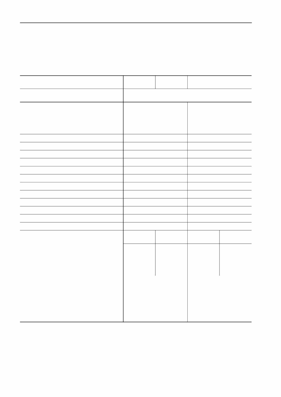
01-8 PC400/450(LC)-7 GENERAL WEIGHT TABLE WEIGHT TABLE PC400-7, PC400LC-7 k This weight table is for use when handling components or when transporting the machine. Unit: kg Machine model PC400-7 PC400LC-7 Serial Number 50001 and up Engine assembly • Engine • Damper • Hydraulic pump 1,500 1,150 14.7 210 1,500 1,150 14.7 210 Radiator, oil cooler assembly 195 195 Hydraulic tank, filter assembly (excluding hydraulic oil) 198 198 Fuel tank (excluding fuel) 251 251 Revolving frame 3,297 3,297 Operator's cab 279 279 Operator's seat 35 35 Counterweight 9,220 9,500 Swing machinery (including swing motor) 526 526 Control valve (with service valve) 257 257 Swing motor 105 105 Travel motor 208 × 2 208 × 2 Center swivel joint 40 40 • Track frame assembly • Track frame • • Center frame • • Crawler frame • Swing circle • Idler • Idler cushion • Carrier roller • Track roller • Final drive (including travel motor) Fixed gauge specification Variable gauge specification Fixed gauge specification Variable gauge specification 10,173 11,367 10,965 11,934 5,506 6,766 6,077 7,096 — 3,229 — 3,229 — 1,754 × 2 — 1,921 × 2 605 × 2 230 × 2 338 × 2 32 × 4 72 × 14 722 × 2 605 × 2 230 × 2 338 × 2 32 × 4 72 × 16 722 × 2
This is the complete official full factory service repair manual for the Komatsu PC400-7 PC450-7 Hydraulic Excavator. Whether you are a professional mechanic or a DIY enthusiast, this manual provides you with all the necessary repair and service information. It is an inexpensive way to ensure your vehicle is working properly and includes step-by-step instructions based on the complete disassembly of the machine. The manual covers various aspects including brakes, clutch, cab, cooling system, diesel fuel system, electrical system, engine, and more. It also features detailed substeps, notes, cautions, warnings, numbered instructions, illustrations, drawings, photos, and troubleshooting and electrical service procedures combined with detailed wiring diagrams. The manual is available in .PDF format, which can work under all PC-based Windows operating systems and Mac as well. It is printable without any restriction and can be saved to your hard drive or burned to CD-ROM. The language of the manual is English, and it requires Adobe Reader for access. Get your Komatsu PC400-7 PC450-7 Hydraulic Excavator service manual now to have all the information you need at your fingertips.
Recently Viewed
5,521,897Happy Clients
2,594,462eManuals
1,120,453Trusted Sellers
15Years in Business
Price:
Actual Price:
Komatsu PC400-7 PC450-7 Excavator Workshop Service Manual