

Komatsu PC220LC-6 Excavator OEM Service & Repair Manual
What's Included?
Fast Download Speeds
Offline Viewing
Access Contents & Bookmarks
Full Search Facility
Print one or all pages of your manual
Operation & Maintenance
Wanual
CEAMOOOI 01
PC200 2ooKli
PC21 llks
Pc22olc4
PC25Ok
HYDRAULIC EXCAVATOR
SERIAL NUMBERS
PC21 ON-6
PC200,2OOLC-6 - A82001 - A83000
- A82001 - A83000
PC22OLC-6 = A82001 - A83000
PC25OLC-6 q A82001 - A83000
This material is proprietary to Komatsu America Intemational Company and is not to be reproduced, used, or
disclosed except in accordance with written authorization from Komatsu America international Company.
It is our policy to improve our products whenever it is possible and practical to do so. We reserve the right to make
changes or add improvements at any time without incurring any obligation to install such changes on products sold
previously.
Due to this continuous program of research and development, periodic revisions may be made to this publication.
it is recommended that customers contact their distributor for information on the latest revision.
December 1996
Copyright 1996 Komatsu America International Company

A WARNING
Unsafe use of this machine may cause serious injury or death.
Operators and maintenance personnel must read this manual
before operating or maintaining this machine. This manual
should be kept near the machine for reference and periodically
reviewed by all personnel who come in contact with it.
CALIFORNIA
Proposition 65 Warning
Diesel engine exhaust and some of its constituents are known
to the State of California to cause cancer, birth defects and
other reproductive harm.

0-1
1. FORWARD
This manual describes procedures for operation, handling, lubrication, maintenance, checking, and adjustment. It will
help the operator and maintenance personnel realize peak performance through effective, economical and safe
machine operation and maintenance.
Keep this manual handy and have all personnel read it periodically. If this manual is lost or becomes dirty and can not
be read, request a replacement manual from your local distributor.
If you sell the machine, be sure to give this manual to the new owner.
Continuing improvements in the design of this machine can lead to changes in detail, which may not be reflected in
this manual. Consult your local distributor or Komatsu America International Company for the latest available
information on your machine or for questions regarding information in this manual.
WARNING
! Improper operation and maintenance of this machine can be hazardous and could result in serious
injury or death.
! Operators and maintenance personnel must read this manual thoroughly before operating or
maintaining this machine.
! This manual should be kept near the machine for reference and periodically reviewed by all
personnel who come across it.
! Some actions involved in operation and maintenance can cause a serious accident, if they are not
performed in the manner described in this manual.
! The procedures and precautions given in this manual apply only to intended uses of the machine. If
you use your machine for any unintended uses that are not specifically prohibited, you must be sure
that it is safe for you and others. In no event should you or others engage in prohibited uses or
actions as described in this manual.
! Komatsu America International Company delivers machines that comply with all applicable
regulations and standards of the country to which it has been shipped. If this machine has been
purchased in another country or purchased from someone in another country, it may lack certain
safety features and specifications that are necessary for use in your country. If there is any question
about whether your product complies with the applicable standards and regulations of your country,
consult your local distributor or Komatsu America International Company before operating the
machine.
The description of safety is given in SAFETY INFORMATION on page 0-2 and in SAFETY from page 1-1.

0-2
2. SAFETY INFORMATION
Most accidents are caused by the failure to follow fundamental safety rules for the operation and maintenance of
machines.
To avoid accidents, read, understand and follow all precautions and warnings in this manual and on the machine
before performing maintenance and machine operations.
To identify safety messages in this manual and on machine product graphics, the following signal words are used.
DANGER- This word is used on safety messages and product graphics where there is a high
probability of serious injury or death if the hazard is not avoided. These safety
messages and product graphics usually describe precautions that must be taken to
avoid the hazard. Failure to avoid this hazard may also result in serious damage to
the machine.
WARNING- This word is used on safety messages and product graphics where there is a
potentially dangerous situation, which could result in serious injury or death if the
hazard is not avoided. These safety messages and product graphics usually
describe precautions that must be taken to avoid the hazard. Failure to avoid this
hazard may also result in serious damage to the machine.
CAUTION- This word is used on safety messages and product graphics for hazards, which
could result in minor or moderate injury if the hazard is not avoided. These safety
messages and product graphics might also use this word for hazards where the
only result could be damage to the machine.
NOTICE- This word is used for precautions that must be taken to avoid actions, which could
shorten the life of the machine.
Safety precautions are described in SAFETY beginning on page 1-1.
Komatsu America International Company cannot predict every circumstance that might involve a potential hazard in
operation and maintenance. Therefore the safety message in this manual and on the machine may not include all
possible safety precautions. If any procedures or actions not specifically recommended or allowed in this manual are
used, you must be sure that you and others can do such procedures and actions safely and without damaging the
machine. If you are unsure about the safety of some procedures, contact your local distributor or Komatsu America
International Company.

0-3
3. INTRODUCTION
3.1 INTENDED USE
This Komatsu HYDRAULIC EXCAVATOR is designed to be used mainly for the following work:
! Digging work
! Smoothing work
! Ditching work
! Loading work
See the section 12.14 WORK POSSIBLE USING HYDRAULIC EXCAVATOR on page 2-74 for further details.
3.2 FEATURES
! This Komatsu HYDRAULIC EXCAVATOR is equipped with various controls based on an advanced electronics
system.
" The monitor panel greatly facilitates daily maintenance and self-diagnosis.
" Working mode, travel speed and swing priority are selective.
" Digging and lifting force can be increased by light-touch control.
(For details, see operation section.)
! Adjustable wrist control, levers make operations smooth and easy.
! Armrest with vertical adjustment for providing optimum operating posture.
! Air-conditioned operator’s cab assures comfortable operation.
! Low noise level and smart urban-style design and coloring.
! Superb operating performance provided by a powerful engine and high performance hydraulic pumps.
! Low fuel consumption controlled by an electronic system provides an environment-friendly machine.
3.3 BREAKING IN A NEW MACHINE
Your Komatsu machine has been thoroughly adjusted and tested before shipment. However, operating the
machine under severe conditions at the beginning can adversely affect the performance and shorten the machine
life.
Be sure to break in the machine for the initial 100 hours (as indicated by the service meter).
During breaking in:
! After starting, let the engine idle for 5 minutes to allow proper engine warm-up prior to actual operation.
! Avoid operation with heavy loads or at high speeds.
! Avoid sudden starts or acceleration, unnecessarily abrupt stops and sharp steering except in cases of
emergency.
Additionally, for the first 20 hours:
! Avoid operating engine for prolonged periods at constant speed (including idle).
! Avoid high speed traveling for periods of more than 5 minutes.
Pay particular attention to oil pressure and temperature indicators, and check coolant and oil levels frequently
during break in.
The precautions given in this manual for operating, maintenance, and safety procedures are only those that apply
when this product is used for the specified purpose. If the machine is used for a purpose that is not listed in this
manual, Komatsu America International Company cannot bear any responsibility for safety. All consideration of
safety in such operations is the responsibility of the user.
Operations that are prohibited in this manual must never be carried out under any circumstance.
0-4
4. LOCATION OF PLATES, TABLE TO ENTER
SERIAL NO. AND DISTRIBUTOR
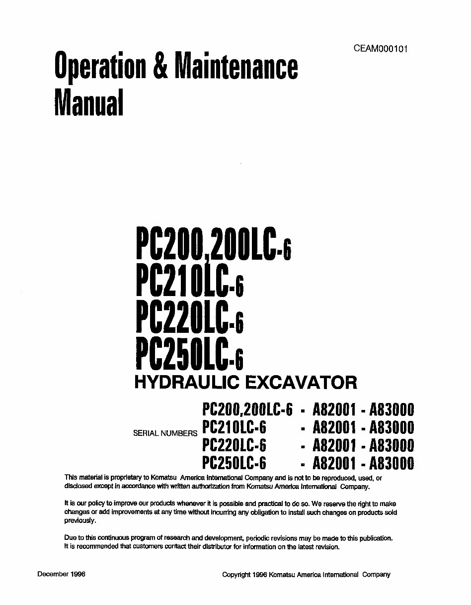
4.1 MACHINE SERIAL NO. PLATE POSITION
On the front bottom right of the operator’s cab
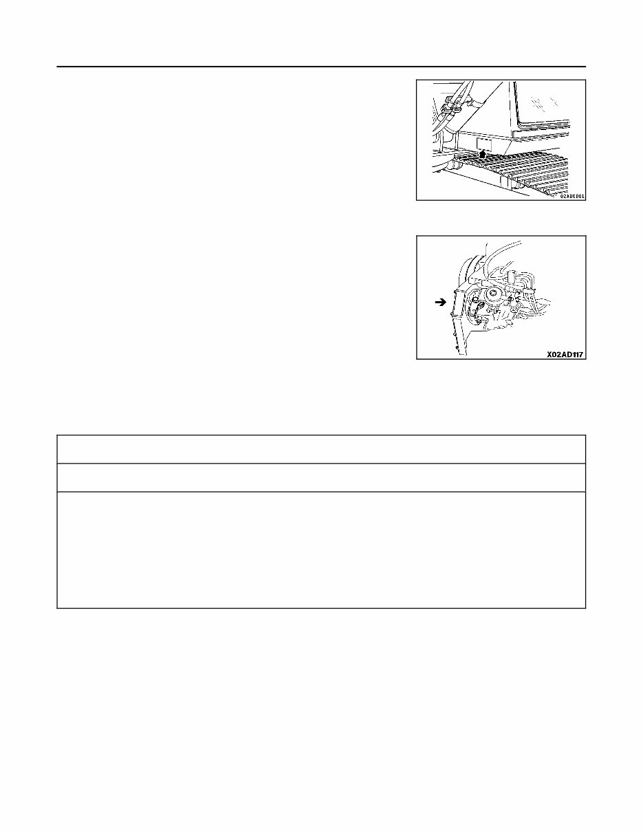
4.2 ENGINE SERIAL NO. PLATE POSITION
On the upper side of the engine cylinder head cover.
4.3 TABLE TO ENTER SERIAL NO. AND DISTRIBUTOR
Machine serial No.:
Engine serial No.:
Distributor name:
Address: Phone:
Service personnel for your machine:
REMARKS

0-5
5. CONTENTS
1. FORWARD .......................................................................... 0-1
2. SAFETY INFORMATION ................................................................ 0-2
3. INTRODUCTION ...................................................................... 0-3
3.1 INTENDED USE ..................................................................... 0-3
3.2 FEATURES ........................................................................ 0-3
3.3 BREAKING IN A NEW MACHINE ....................................................... 0-3
4. LOCATION OF PLATES, TABLE TO ENTER SERIAL NO. AND DISTRIBUTOR .................... 0-4
4.1 MACHINE SERIAL NO. PLATE POSITION ................................................ 0-4
4.2 ENGINE SERIAL NO. PLATE POSITION ................................................. 0-4
4.3 TABLE TO ENTER SERIAL NO. AND DISTRIBUTOR ....................................... 0-4
5. CONTENTS .......................................................................... 0-5
6. GENERAL PRECAUTIONS .............................................................. 1-2
7. PRECAUTIONS DURING OPERATION .................................................... 1-9
7.1 BEFORE STARTING ENGINE .......................................................... 1-9
7.2 OPERATING MACHINE .............................................................. 1-11
7.3 TRANSPORTATION ................................................................ 1-17
7.4 BATTERY ......................................................................... 1-18
7.5 TOWING .......................................................................... 1-19
7.6 BUCKET WITH HOOK ............................................................... 1-20
7.6.1 GENERAL PRECAUTIONS ........................................................ 1-20
7.6.2 PRECAUTIONS FOR LIFTING OPERATION .......................................... 1-21
8. PRECAUTIONS FOR MAINTENANCE .................................................... 1-22
8.1 BEFORE CARRYING OUT MAINTENANCE .............................................. 1-22
8.2 DURING MAINTENANCE ............................................................ 1-25
9. POSITION FOR ATTACHING SAFETY LABELS ............................................ 1-29
10. GENERAL VIEW ...................................................................... 2-2
10.1 GENERAL VIEW OF MACHINE ....................................................... 2-2
10.2 GENERAL VIEW OF CONTROLS AND GAUGES ......................................... 2-3
11. EXPLANATION OF COMPONENTS ....................................................... 2-4
11.1 MACHINE MONITOR ............................................................... 2-4
11.1.1 BASIC CHECK ITEMS ........................................................... 2-4
11.1.2 CAUTION ITEMS ............................................................... 2-5
11.1.3 EMERGENCY STOP ITEMS ...................................................... 2-5
11.1.4 METER DISPLAY PORTION ...................................................... 2-5
11.1.5 SWITCHES .................................................................... 2-5
11.2 METER ......................................................................... 2-15
11.3 SWITCHES ...................................................................... 2-16
11.4 CONTROL LEVERS, PEDALS ....................................................... 2-20
11.5 CEILING WINDOW ................................................................ 2-25
11.6 FRONT WINDOW ................................................................. 2-26
11.7 DOOR LOCK ..................................................................... 2-28
11.8 CAP, COVER WITH LOCK .......................................................... 2-29
11.8.1 METHOD OF OPENING AND CLOSING CAP WITH LOCK ............................. 2-29
11.8.2 METHOD OF OPENING AND CLOSING COVER WITH LOCK .......................... 2-29
11.9 HOT/COOL BOX .................................................................. 2-30

5. CONTENTS
0-6
11.10 LUGGAGE BOX ................................................................. 2-30
11.11 ASHTRAY ..................................................................... 2-30
11.12 CAB HEATER .................................................................. 2-31
11.13 CAR RADIO .................................................................... 2-33
11.13.1 EXPLANATION OF COMPONENTS ............................................... 2-33
11.13.2 LOCATION AND FUNCTION OF CONTROLS ....................................... 2-33
11.13.3 METHOD OF OPERATION ...................................................... 2-36
11.13.4 PRECAUTIONS WHEN USING ................................................... 2-37
11.13.5 SPECIFICATIONS ............................................................. 2-37
11.14 FUSE ......................................................................... 2-38
11.15 FUSIBLE LINK .................................................................. 2-39
11.16 CONTROLLERS ................................................................ 2-39
11.17 TOOL BOX ..................................................................... 2-39
11.18 GREASE PUMP HOLDER ......................................................... 2-39
11.19 HANDLING ACCUMULATOR ...................................................... 2-40
11.19.1 METHOD OF RELEASING PRESSURE IN CONTROL CIRCUIT ON MACHINE
EQUIPPED WITH ACCUMULATOR ............................................... 2-40
12. OPERATION ........................................................................ 2-41
12.1 CHECK BEFORE STARTING ENGINE ................................................ 2-41
12.1.1 WALK-AROUND CHECK ........................................................ 2-41
12.1.2 CHECK BEFORE STARTING .................................................... 2-43
12.1.3 ADJUSTMENT BEFORE OPERATION ............................................. 2-47
12.1.4 OPERATIONS AND CHECKS BEFORE STARTING ENGINE ........................... 2-49
12.2 STARTING ENGINE ............................................................... 2-50
12.2.1 NORMAL STARTING ........................................................... 2-50
12.2.2 STARTING IN COLD WEATHER .................................................. 2-51
12.3 OPERATIONS AND CHECKS AFTER STARTING ENGINE ................................ 2-53
12.3.1 WHEN NORMAL .............................................................. 2-53
12.3.2 IN COLD AREAS .............................................................. 2-55
12.4 MOVING MACHINE ............................................................... 2-58
12.4.1 MOVING MACHINE FORWARD .................................................. 2-58
12.4.2 MOVING MACHINE BACKWARD ................................................. 2-59
12.5 STEERING MACHINE ............................................................. 2-61
12.5.1 STEERING (CHANGING DIRECTION) ............................................. 2-61
12.6 STOPPING MACHINE ............................................................. 2-63
12.7 SWINGING ...................................................................... 2-64
12.8 OPERATION OF WORK EQUIPMENT ................................................ 2-65
12.9 WORKING MODE SELECTION ...................................................... 2-66
12.10 PROHIBITIONS FOR OPERATION ................................................. 2-68
12.11 PRECAUTIONS FOR OPERATION ................................................. 2-70
12.12 PRECAUTIONS WHEN TRAVELING UP OR DOWN HILLS .............................. 2-71
12.13 HOW TO ESCAPE FROM MUD .................................................... 2-73
12.13.1 WHEN ONE SIDE IS STUCK ..................................................... 2-73
12.13.2 WHEN BOTH SIDES ARE STUCK ................................................ 2-73
12.14 WORK POSSIBLE USING HYDRAULIC EXCAVATOR .................................. 2-74
12.14.1 BACKHOE WORK ............................................................. 2-74
12.14.2 SHOVEL WORK ............................................................... 2-74
12.14.3 DITCHING WORK ............................................................. 2-74
12.14.4 LOADING WORK .............................................................. 2-74
12.15 REPLACEMENT AND INVERSION OF BUCKET ....................................... 2-75
12.15.1 REPLACEMENT ............................................................... 2-75
12.15.2 INVERSION .................................................................. 2-76
12.16 PARKING MACHINE ............................................................. 2-77
12.17 CHECK AFTER FINISHING WORK ................................................. 2-78
12.18 STOPPING ENGINE ............................................................. 2-79
12.19 CHECK AFTER STOPPING ENGINE ................................................ 2-80
12.20 LOCKING AND SECURING MACHINE ............................................... 2-80

5. CONTENTS
0-7
13. TRANSPORTATION .................................................................. 2-81
13.1 LOADING, UNLOADING WORK ..................................................... 2-81
13.2 PRECAUTIONS FOR LOADING ..................................................... 2-83
13.3 PRECAUTIONS FOR TRANSPORTATION ............................................. 2-84
14. COLD WEATHER OPERATION ......................................................... 2-85
14.1 PRECAUTIONS FOR LOW TEMPERATURE ........................................... 2-85
14.1.1 FUEL AND LUBRICANTS ....................................................... 2-85
14.1.2 COOLANT ................................................................... 2-85
14.1.3 BATTERY .................................................................... 2-86
14.2 PRECAUTIONS AFTER COMPLETION OF WORK ...................................... 2-87
14.3 AFTER COLD WEATHER .......................................................... 2-87
15. LONG-TERM STORAGE ............................................................... 2-88
15.1 BEFORE STORAGE ............................................................... 2-88
15.2 DURING STORAGE ............................................................... 2-89
15.3 AFTER STORAGE ................................................................ 2-89
15.4 STARTING MACHINE AFTER LONG-TERM STORAGE .................................. 2-89
16. TROUBLESHOOTING ................................................................. 2-90
16.1 PHENOMENA THAT ARE NOT FAILURES ............................................. 2-90
16.2 METHOD OF TOWING MACHINE .................................................... 2-90
16.3 METHOD FOR USING LIGHT-WEIGHT TOWING HOLE .................................. 2-90
16.4 PRECAUTIONS ON PARTICULAR JOBSITES .......................................... 2-91
16.5 IF BATTERY IS DISCHARGED ...................................................... 2-91
16.5.1 STARTING ENGINE WITH BOOSTER CABLE ....................................... 2-92
16.6 OTHER TROUBLE ................................................................ 2-94
16.6.1 ELECTRICAL SYSTEM ......................................................... 2-94
16.6.2 CHASSIS .................................................................... 2-95
16.6.3 ENGINE ..................................................................... 2-96
16.6.4 ELECTRONIC CONTROL SYSTEM ............................................... 2-98
17. GUIDES TO MAINTENANCE ............................................................ 3-2
18. OUTLINES OF SERVICE ............................................................... 3-5
18.1 OUTLINE OF OIL, FUEL, COOLANT ................................................... 3-5
18.1.1 OIL .......................................................................... 3-5
18.1.2 FUEL ......................................................................... 3-6
18.1.3 COOLANT .................................................................... 3-6
18.1.4 GREASE ...................................................................... 3-7
18.1.5 STORING OIL AND FUEL ........................................................ 3-7
18.1.6 FILTERS ...................................................................... 3-7
18.2 OUTLINE OF ELECTRICAL SYSTEM .................................................. 3-8
18.3 OUTLINE OF HYDRAULIC SYSTEM ................................................... 3-9
19. WEAR PARTS LIST .................................................................. 3-10
20. USE OF FUEL, COOLANT AND LUBRICANTS ACCORDING TO AMBIENT TEMPERATURE ........ 3-12
20.1 ENGINE OIL SPECIFICATION ....................................................... 3-13
21. STANDARD TIGHTENING TORQUES FOR BOLTS AND NUTS ............................... 3-15
21.1 INTRODUCTION OF NECESSARY TOOLS ............................................ 3-15
21.2 TORQUE LIST ................................................................... 3-16
22. PERIODIC REPLACEMENT OF SAFETY CRITICAL PARTS .................................. 3-17
23. MAINTENANCE SCHEDULE CHART ..................................................... 3-19
23.1 MAINTENANCE SCHEDULE CHART ................................................. 3-19
23.2 MAINTENANCE INTERVAL WHEN USING HYDRAULIC BREAKER ......................... 3-21

5. CONTENTS
0-8
24. SERVICE PROCEDURE ............................................................... 3-22
24.1 INITIAL 250 HOURS SERVICE ...................................................... 3-22
24.2 WHEN REQUIRED ................................................................ 3-23
24.2.1 CHECK, CLEAN AND REPLACE AIR CLEANER ELEMENT ............................ 3-23
24.2.2 CLEAN INSIDE OF COOLING SYSTEM ............................................ 3-25
24.2.3 CHECK AND TIGHTEN TRACK SHOE BOLTS ...................................... 3-29
24.2.4 CHECK AND ADJUST TRACK TENSION ........................................... 3-30
24.2.5 CHECK ENGINE INTAKE AIR HEATER (ELECTRICAL) ............................... 3-32
24.2.6 INSTALLATION OF BUCKET TEETH (ESCO VERTALOK® TYPE) ....................... 3-33
24.2.7 INSTALLATION OF BUCKET TEETH (ESCO SUPERV ® TYPE) ........................ 3-36
24.2.8 REMOVAL OF BUCKET TEETH (ESCO VERTALOK® TYPE) ........................... 3-38
24.2.9 REMOVAL OF BUCKET TEETH (ESCO SUPERV ® TYPE) ............................ 3-40
24.2.10 ADJUST BUCKET CLEARANCE ................................................ 3-42
24.2.11 CHECK WINDOW WASHER FLUID LEVEL, ADD FLUID ............................. 3-43
24.2.12 CHECK AND ADJUST AIR CONDITIONER ........................................ 3-44
24.2.13 REPLACE ADDITIONAL BREAKER FILTER ELEMENT .............................. 3-45
24.2.14 CLEAN INLINE FILTER (CYLINDRICAL HOUSING) ................................. 3-46
24.2.15 CLEAN INLINE FILTER (RECTANGULAR HOUSING) ............................... 3-47
24.3 CHECK BEFORE STARTING ........................................................ 3-48
24.3.1 CHECK COOLANT LEVEL, ADD COOLANT ......................................... 3-48
24.3.2 CHECK OIL LEVEL IN ENGINE OIL PAN, ADD OIL ................................... 3-48
24.3.3 CHECK FUEL LEVEL, ADD FUEL ............................................... 3-49
24.3.4 CHECK OIL LEVEL IN HYDRAULIC TANK, ADD OIL ................................ 3-50
24.3.5 CHECK AIR CLEANER FOR CLOGGING ......................................... 3-50
24.3.6 CHECK ELECTRIC WIRING .................................................... 3-51
24.3.7 CHECK FOR WATER AND SEDIMENT IN SEDIMENTOR, DRAIN WATER AND SEDIMENT .. 3-51
24.4 EVERY 100 HOURS SERVICE ....................................................... 3-52
24.4.1 LUBRICATING ................................................................ 3-52
24.4.2 CHECK OIL LEVEL IN SWING MACHINERY CASE, ADD OIL ........................... 3-54
24.4.3 DRAIN WATER AND SEDIMENT FROM FUEL TANK ................................. 3-54
24.5 EVERY 250 HOURS SERVICE ....................................................... 3-55
24.5.1 CHECK OIL LEVEL IN FINAL DRIVE CASE, ADD OIL ................................. 3-55
24.5.2 CHECK LEVEL OF BATTERY ELECTROLYTE ...................................... 3-56
24.5.3 REPLACE HYDRAULIC FILTER ELEMENT ......................................... 3-57
24.5.4 LUBRICATE SWING CIRCLE .................................................... 3-58
24.5.5 CHECK AIR CONDITIONER COMPRESSOR BELT TENSION, ADJUST .................. 3-59
24.5.6 CHANGE OIL IN ENGINE OIL PAN, REPLACE ENGINE OIL FILTER CARTRIDGE .......... 3-60
24.6 EVERY 500 HOURS SERVICE ....................................................... 3-61
24.6.1 REPLACE FUEL FILTER CARTRIDGE ............................................. 3-61
24.6.2 CHECK SWING PINION GREASE LEVEL, ADD GREASE .............................. 3-63
24.6.3 CLEAN AND INSPECT RADIATOR FINS, OIL COOLER FINS, AFTERCOOLER
FINS AND CONDENSER FINS (ONLY FOR MACHINES EQUIPPED WITH AIR CONDITIONER) 3-64
24.6.4 CLEAN INTERNAL AND EXTERNAL AIR FILTERS OF AIR CONDITIONER SYSTEM ....... 3-65
24.6.5 REPLACE HYDRAULIC TANK BREATHER ELEMENT ................................ 3-65
24.7 EVERY 1000 HOURS SERVICE ...................................................... 3-66
24.7.1 CHANGE OIL IN SWING MACHINERY CASE ....................................... 3-66
24.7.2 CHECK OIL LEVEL IN DAMPER CASE, ADD OIL .................................... 3-67
24.7.3 CHECK ALL TIGHTENING PARTS OF TURBOCHARGER ............................. 3-67
24.7.4 CHECK PLAY OF TURBOCHARGER ROTOR ....................................... 3-67
24.7.5 CHECK AND ADJUST VALVE CLEARANCE ........................................ 3-68
24.7.6 CHECK FAN BELT TENSIONER BEARING, BELT AND FAN HUB ....................... 3-69
24.7.7 CHECK FAN BELT TENSION .................................................... 3-69
24.8 EVERY 2000 HOURS SERVICE ...................................................... 3-70
24.8.1 CHANGE OIL IN FINAL DRIVE CASE .............................................. 3-70
24.8.2 CHANGE OIL IN HYDRAULIC TANK, CLEAN STRAINER .............................. 3-71
24.8.3 CLEAN, CHECK TURBOCHARGER ............................................... 3-74
24.8.4 CHECK ALTERNATOR, STARTING MOTOR ........................................ 3-74
24.8.5 CHECK VIBRATION DAMPER ................................................... 3-74
You're Reading a Preview
What's Included?
Fast Download Speeds
Offline Viewing
Access Contents & Bookmarks
Full Search Facility
Print one or all pages of your manual
$39.99
Viewed 18 Times Today


Secure transaction
What's Included?
Fast Download Speeds
Offline Viewing
Access Contents & Bookmarks
Full Search Facility
Print one or all pages of your manual
$39.99
- The Komatsu PC220LC-6 Excavator Service & Repair Manual is a comprehensive technical resource for maintaining and repairing this specific excavator model.
- It contains accurate instructions sourced directly from Komatsu for diagnosing issues and performing service procedures on key systems, including hydraulic system troubleshooting and electrical wiring diagrams.
- The manual provides clear explanations, diagrams, torque specifications, and maintenance schedules to simplify each process, from routine checks to significant repairs.
- It offers insights into engine specifications, hydraulic system functionality, and component disassembly to ensure optimal performance.
- Useful for both experienced technicians and DIY repair enthusiasts, this manual is indispensable for ensuring the reliability and longevity of the Komatsu PC220LC-6.
- It empowers users to handle basic maintenance and advanced diagnostics with confidence.
- Printable: Yes
- Language: English
- Compatibility: Pretty much any electronic device, including PC & Mac computers, Android and Apple smartphones & tablets, etc.
- Requirements: Adobe Reader (free)


