KOMATSU PC200-6 Hydraulic Excavator Service Shop Repair Manual (S/N: C10001 and up)
What's Included?
Lifetime Access
Fast Download Speeds
Online & Offline Access
Access PDF Contents & Bookmarks
Full Search Facility
Print one or all pages of your manual
Shop Manual SEBMOI 0201 K PC200 HYDRAULIC EXCAVATOR SERIAL NUMBERS PC200-6 - Cl0001 andup This material is proprietary to Komatsu America International Company and is not to be reproduced, used, or disclosed except in accordance with written authorization from Komatsu America International Company. It is our policy to improve our products whenever it is possible and practical to do so. We reserve the right to make changes or add improvements at any time without incurring any obligation to install such changes on products sold previously. Due to this continuous program of research and development, periodic revisions may be made to this publication. It is recommended that customers contact their distributor for information on the latest revision. February 1998 Copyright 1998 Komatsu America International Company
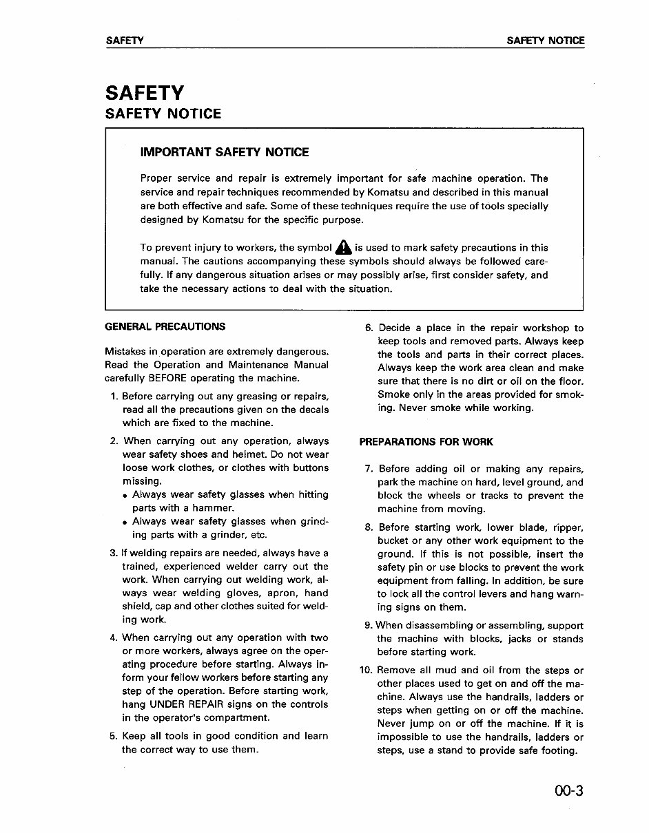
SAFETY SAFETY NOTICE SAFETY SAFETY NOTICE IMPORTANT SAFETY NOTICE Proper service and repair is extremely important for safe machine operation. The service and repair techniques recommended by Komatsu and described in this manual are both effective and safe. Some of these techniques require the use of tools specially designed by Komatsu for the specific purpose. To prevent injury to workers, the symbol A is used to mark safety precautions in this manual. The cautions accompanying these symbols should always be followed care- fully. If any dangerous situation arises or may possibly arise, first consider safety, and take the necessary actions to deal with the situation. GENERAL PRECAUTIONS 6. Mistakes in operation are extremely dangerous. Read the Operation and Maintenance Manual carefully BEFORE operating the machine. Before carrying out any greasing or repairs, read all the precautions given on the decals which are fixed to the machine. When carrying out any operation, always wear safety shoes and helmet. Do not wear loose work clothes, or clothes with buttons missing. . Always wear safety glasses when hitting parts with a hammer. . Always wear safety glasses when grind- ing parts with a grinder, etc. If welding repairs are needed, always have a trained, experienced welder carry out the work. When carrying out welding work, al- ways wear welding gloves, apron, hand shield, cap and other clothes suited for weld- ing work. When carrying out any operation with two or more workers, always agree on the oper- ating procedure before starting. Always in- form your fellow workers before starting any step of the operation. Before starting work, hang UNDER REPAIR signs on the controls in the operator’s compartment. 5. Keep all tools in good condition and learn the correct way to use them. Decide a place in the repair workshop to keep tools and removed parts. Always keep the tools and parts in their correct places. Always keep the work area clean and make sure that there is no dirt or oil on the floor. Smoke only in the areas provided for smok- ing. Never smoke while working. PREPARATIONS FOR WORK 7. 8. 9. 10. Before adding oil or making any repairs, park the machine on hard, level ground, and block the wheels or tracks to prevent the machine from moving. Before starting work, lower blade, ripper, bucket or any other work equipment to the ground. If this is not possible, insert the safety pin or use blocks to prevent the work equipment from falling. In addition, be sure to lock all the control levers and hang warn- ing signs on them. When disassembling or assembling, support the machine with blocks, jacks or stands before starting work. Remove all mud and oil from the steps or other places used to get on and off the ma- chine. Always use the handrails, ladders or steps when getting on or off the machine. Never jump on or off the machine. If it is impossible to use the handrails, ladders or steps, use a stand to provide safe footing. 00-3
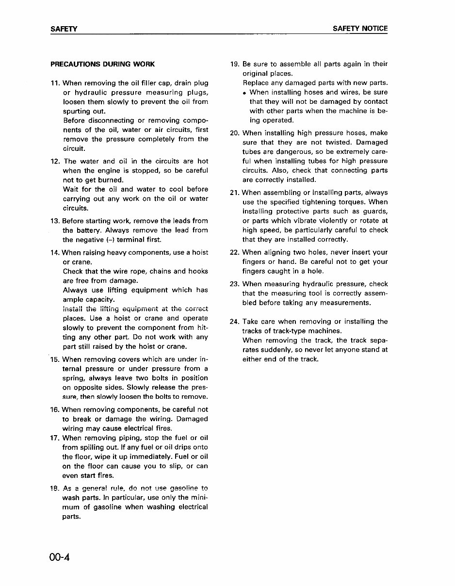
SAFETY SAFETY NOTICE PRECAUTIONS DURING WORK 11. 12. 13. When removing the oil filler cap, drain plug or hydraulic pressure measuring plugs, loosen them slowly to prevent the oil from spurting out. Before disconnecting or removing compo- nents of the oil, water or air circuits, first remove the pressure completely from the circuit. The water and oil in the circuits are hot when the engine is stopped, so be careful not to get burned. Wait for the oil and water to cool before carrying out any work on the oil or water circuits. Before starting work, remove the leads from the battery. Always remove the lead from the negative (-1 terminal first. 14. When raising heavy components, use a hoist or crane. Check that the wire rope, chains and hooks are free from damage. Always use lifting equipment which has ample capacity. Install the lifting equipment at the correct places. Use a hoist or crane and operate slowly to prevent the component from hit- ting any other part. Do not work with any part still raised by the hoist or crane. 15. When removing covers which are under in- ternal pressure or under pressure from a spring, always leave two bolts in position on opposite sides. Slowly release the pres- sure, then slowly loosen the bolts to remove. 16. When removing components, be careful not to break or damage the wiring. Damaged wiring may cause electrical fires. 17. When removing piping, stop the fuel or oil from spilling out. If any fuel or oil drips onto the floor, wipe it up immediately. Fuel or oil on the floor can cause you to slip, or can even start fires. 18. As a general rule, do not use gasoline to wash parts. In particular, use only the mini- mum of gasoline when washing electrical parts. 19. 20. 21. 22. 23. 24. Be sure to assemble all parts again in their original places. Replace any damaged parts with new parts. . When installing hoses and wires, be sure that they will not be damaged by contact with other parts when the machine is be- ing operated. When installing high pressure hoses, make sure that they are not twisted. Damaged tubes are dangerous, so be extremely care- ful when installing tubes for high pressure circuits. Also, check that connecting parts are correctly installed. When assembling or installing parts, always use the specified tightening torques. When installing protective parts such as guards, or parts which vibrate violently or rotate at high speed, be particularly careful to check that they are installed correctly. When aligning two holes, never insert your fingers or hand. Be careful not to get your fingers caught in a hole. When measuring hydraulic pressure, check that the measuring tool is correctly assem- bled before taking any measurements. Take care when removing or installing the tracks of track-type machines. When removing the track, the track sepa- rates suddenly, so never let anyone stand at either end of the track. 00-4
FOREWORD GENERAL FOREWORD GENERAL This shop manual has been prepared as an aid to improve the quality of repairs by giving the serviceman an accurate understanding of the product and by showing him the correct way to perform repairs and make judgements. Make sure you understand the contents of this manual and use it to full effect at every opportunity. This shop manual mainly contains the necessary technical information for operations performed in a service workshop. For ease of understanding, the manual is divided into the following chapters; these chapters are further divided into the each main group of components. STRUCTURE AND FUNCTION This section explains the structure and function of each component. It serves not only to give an understanding of the structure, but also serves as reference material for troubleshooting. TESTING AND ADJUSTING This section explains checks to be made before and after performing repairs, as well as adjustments to be made at completion of the checks and repairs. Troubleshooting charts correlating “Problems” to “Causes” are also included in this section. DISASSEMBLY AND ASSEMBLY This section explains the order to be followed when removing, installing, disassembling or assembling each component, as well as precautions to be taken for these operations. MAINTENANCE STANDARD This section gives the judgement standards when inspecting disassembled parts. NOTICE The specifications contained in this shop manual are subject to change at any time and without any advance notice. Use the specifications given in the book with the latest date. I I 00-5
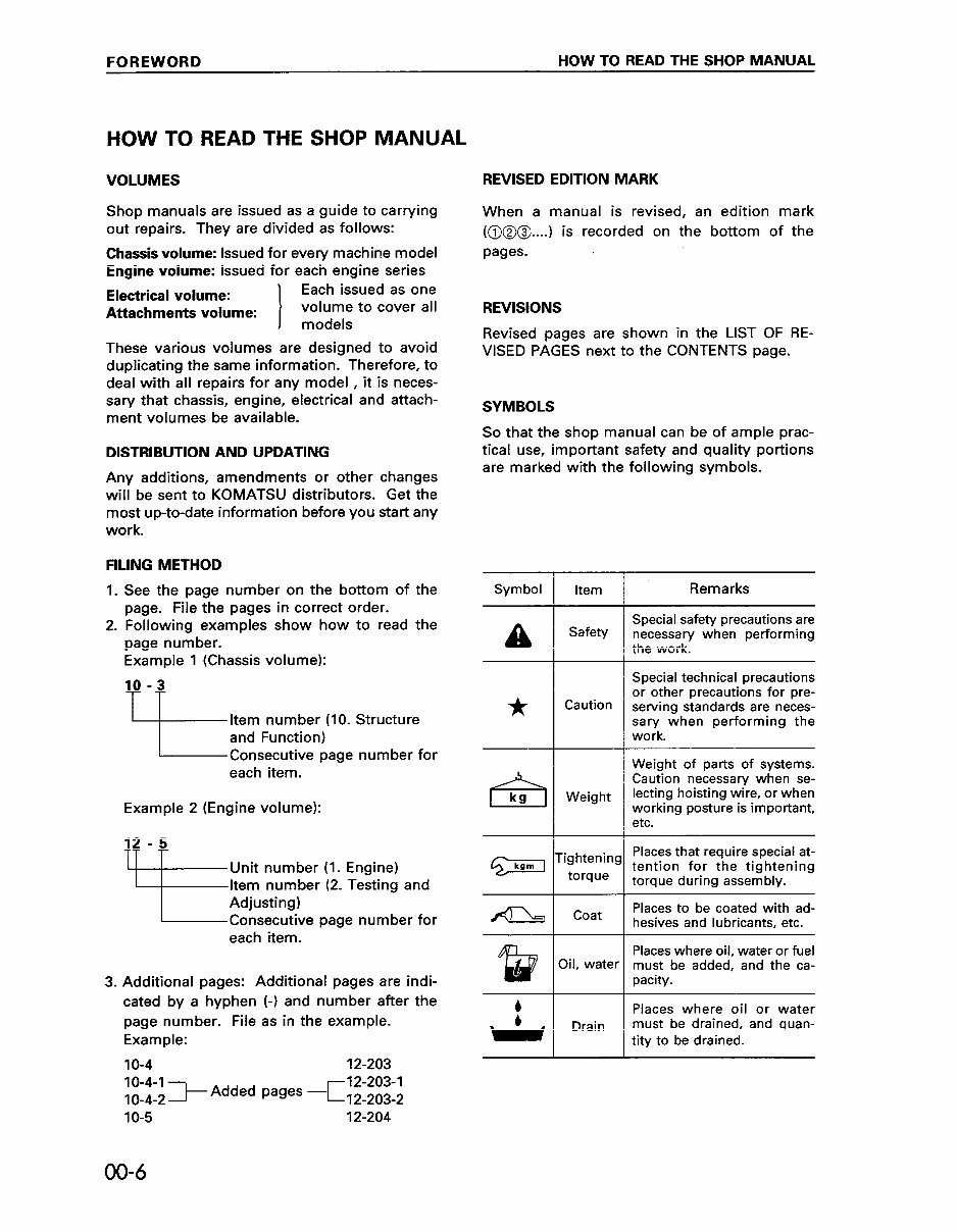
FOREWORD HOW TO READ THE SHOP MANUAL HOW TO READ THE SHOP MANUAL VOLUMES Shop manuals are issued as a guide to carrying out repairs. They are divided as follows: Chassis volume: Issued for every machine model Engine volume: Issued for each engine series Electrical volume: Attachments volume: Each issued as one volume to cover all models These various volumes are designed to avoid duplicating the same information. Therefore, to deal with all repairs for any model , it is neces- sary that chassis, engine, electrical and attach- ment volumes be available. DISTRIBUTION AND UPDATING Any additions, amendments or other changes will be sent to KOMATSU distributors. Get the most up-to-date information before you start any work. FILING METHOD 1. 2. 3. See the page number on the bottom of the page. File the pages in correct order. Following examples show how to read the page number. Example 1 (Chassis volume): 10 -3 Item number (IO. Structure and Function) Consecutive page number for each item. Example 2 (Engine volume): 12 - 5 TT l- -t Unit number (I. Engine) Item number (2. Testing and Adjusting) Consecutive page number for each item. Additional pages: Additional pages are indi- cated by a hyphen (-1 and number after the page number. File as in the example. Example: IO-4 1Z-203 REVISED EDITION MARK When a manual is revised, an edition mark (@I@@....) is recorded on the bottom of the pages. REVISIONS Revised pages are shown in the LIST OF RE- VISED PAGES next to the CONTENTS page. SYMBOLS So that the shop manual can be of ample prac- tical use, important safety and quality portions are marked with the following symbols. Symbol Item A * Safety Caution Weight ighteninc torque Coat Xl. water Drain I Remarks Special safety precautions are necessary when performing the work. Special technical precautions or other precautions for pre- serving standards are neces- sary when performing the work. Weight of parts of systems. Caution necessary when se- lecting hoisting wire, or when working posture is important, etc. Places that require special at- tention for the tightening torque during assembly. Places to be coated with ad- hesives and lubricants, etc. Places where oil, water or fuel must be added, and the ca- pacity. Places where oil or water must be drained, and quan- tity to be drained. 00-6
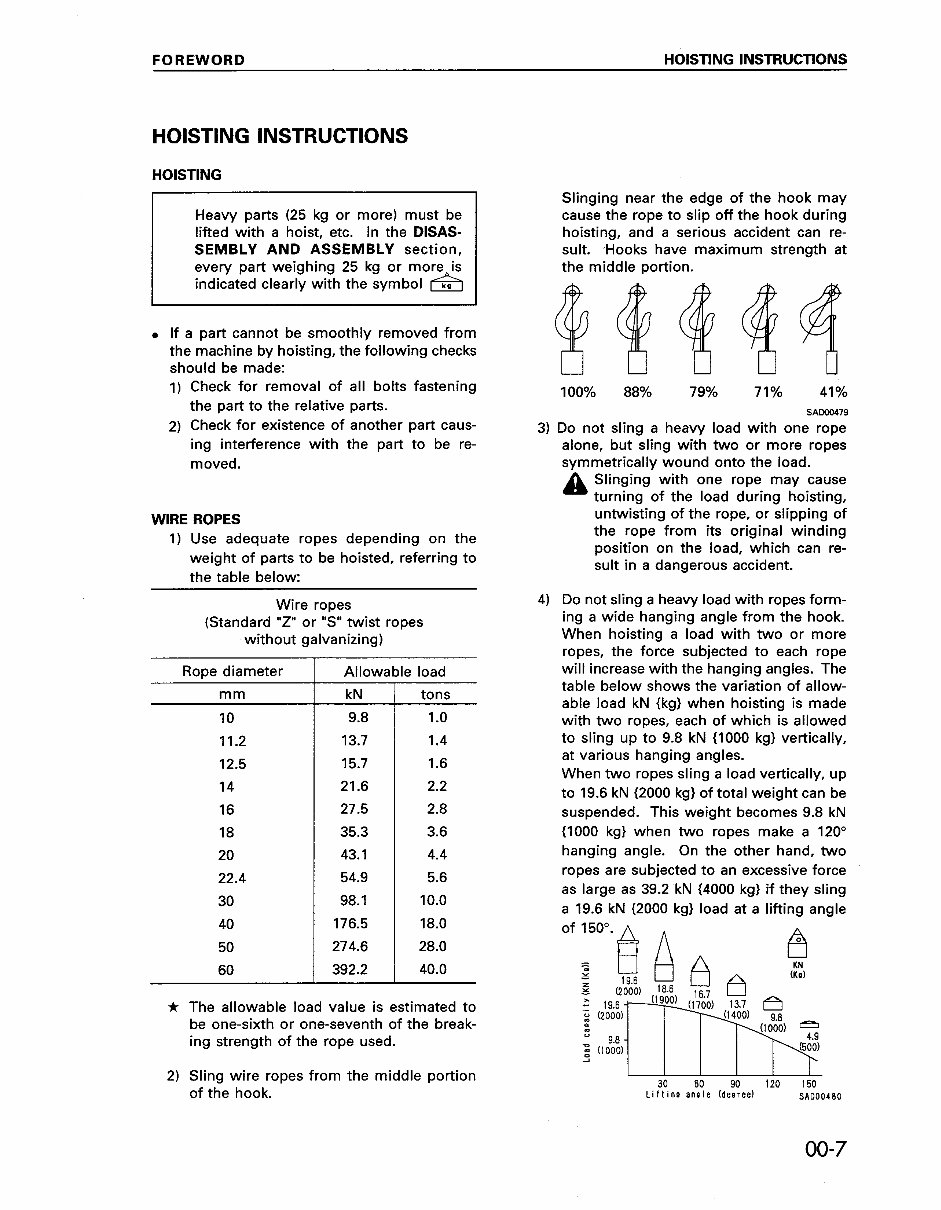
FOREWORD HOISTING INSTRUCTIONS HOISTING INSTRUCTIONS HOISTING Heavy parts (25 kg or more) must be lifted with a hoist, etc. In the DISAS- SEMBLY AND ASSEMBLY section, every part weighing 25 kg or more is indicated clearly with the symbol & . If a part cannot be smoothly removed from the machine by hoisting, the following checks should be made: I) Check for removal of all bolts fastening the part to the relative parts. 2) Check for existence of another part caus- ing interference with the part to be re- moved. WIRE ROPES 1) Use adequate ropes depending on the weight of parts to be hoisted, referring to the table below: Wire ropes (Standard “Z” or “S” twist ropes without galvanizing) Rope diameter mm IO 11.2 12.5 14 16 18 20 22.4 30 40 50 60 -I- Allowable load kN tons 9.8 1.0 13.7 1.4 15.7 1.6 21.6 2.2 27.5 2.8 35.3 3.6 43.1 4.4 54.9 5.6 98.1 10.0 176.5 18.0 274.6 28.0 392.2 40.0 * The allowable load value is estimated to be one-sixth or one-seventh of the break- ing strength of the rope used. 2) Sling wire ropes from the middle portion of the hook. 3) 4) Slinging near the edge of the hook may cause the rope to slip off the hook during hoisting, and a serious accident can re- sult. ,Hooks have maximum strength at the middle portion. 100% 88% 79% 71% 41% SAW0479 Do not sling a heavy load with one rope alone, but sling with two or more ropes symmetrically wound onto the load. A Slinging with one rope may cause turning of the load during hoisting, untwisting of the rope, or slipping of the rope from its original winding position on the load, which can re- sult in a dangerous accident. Do not sling a heavy load with ropes form- ing a wide hanging angle from the hook. When hoisting a load with two or more ropes, the force subjected to each rope will increase with the hanging angles. The table below shows the variation of allow- able load kN {kg} when hoisting is made with two ropes, each of which is allowed to sling up to 9.8 kN II000 kg) vertically, at various hanging angles. When two ropes sling a load vertically, up to 19.6 kN 12000 kg1 of total weight can be suspended. This weight becomes 9.8 kN {IO00 kg) when two ropes make a 120” hanging angle. On the other hand, two ropes are subjected to an excessive force as large as 39.2 kN (4000 kg) if they sling a 19.6 kN f2000 kg) load at a lifting angle of 150”. a A A I I I I I I 30 60 90 120 150 Lifting angle (decree) SAD00480 00-7
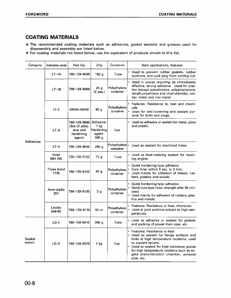
FOREWORD COATING MATERIALS COATING MATERIALS Ir The recommended coating materials such as adhesives, gasket sealants and greases used for disassembly and assembly are listed below. * For coating materials not listed below, use the equivalent of products shown in this list. Categon/ :omatsu code Part No. Q’w Container Main applications, features LT-IA 150 g Tube l Used to prevent rubber gaskets, rubber cushions, and cock plug from coming out. 790-129-9030 l Used in places requiring an immediately ‘olyethylene effective, strong adhesive. Used for plas- container tics (except polyethylene, polyprophylene, tetrafluoroethlene and vinyl chloride), rub- ber, metal and non-metal. l Features: Resistance to heat and chemi- ‘olyethylene cals container l Used for anti-loosening and sealant pur- pose for bolts and plugs. I I I F 1 F F LT-1 B 790-129-9050 20 9 (2 pes.) 50 g LT-2 0994040030 790-I 29-9060 (Set of adhe- sive and hardening agent) Adhesive: 1 kg iardeninc agent: 500 g Can l Used as adhesive or sealant for metal, glass and plastic. ‘olyethylene . Used as sealant for machined holes. container LT-3 Adhesives LT-4 790-129-9040 250 g 790-126-9120 75 g Tube l Used as heat-resisting sealant for repair- ing engine. Holtz MH 705 l Quick hardening type adhesive l Used mainly for adhesion of metals, rub- Three bond 1735 790-129-9140 50 g l Quick hardening type adhesive ‘olyethylene l Quick cure type (max. strength after 30 min- container utes) l Used mainly for adhesion of rubbers, plas- Aron-alpha 201 29 790-129-9130 1 tics and metals. ‘olyethylene l Features: Resistance to heat, chemicals l container Used at joint portions subject to high tem- peratures. Tube l Used as adhesive or sealant for gaskets and packing of power train case, etc. Loctite 648-50 r9A-129-9110 LG-1 790-129-9010 50 cc 200 g 1 kg Features: Resistance to heat Used as sealant for flange surfaces and bolts at high temperature locations, used to prevent seizure. Used as sealant for heat resistance gasket for high temperature locations such as en- gine precombustion chamber, exhaust pipe, etc. . . Can . Gasket sealant LG-3 790-l 29-9070 00-8
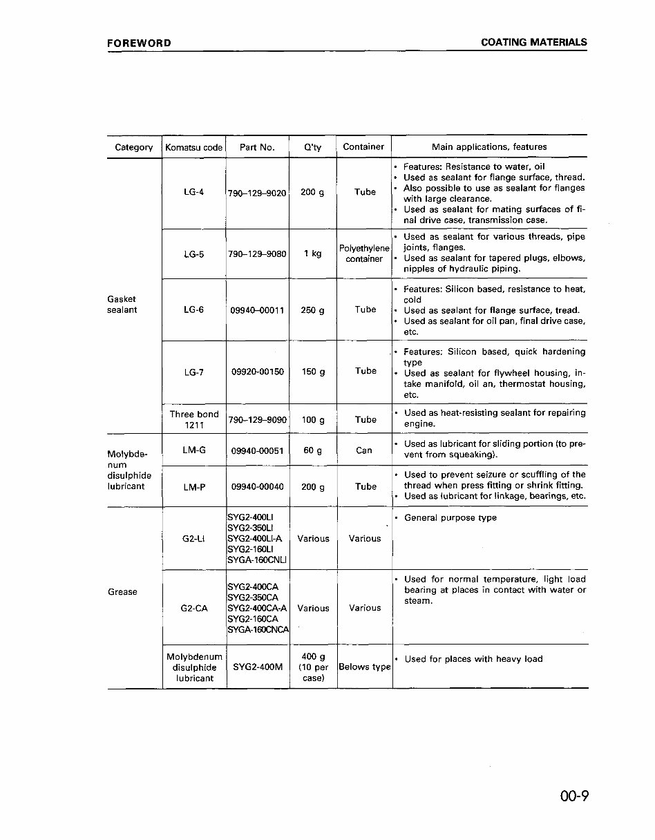
FOREWORD COATING MATERIALS Category Komatsu code Part No. o’ty Container Main applications, features l Features: Resistance to water, oil l Used as sealant for flange surface, thread. I LG-4 790-129-9020 200 g Tube l Also possible to use as sealant for flanges with lame clearance. l Used assealant for mating surfaces of fi- nal drive case, transmission case. l Used as sealant for various threads, pipe LG-5 1790-129-9060 1 1 kg / p;;,$;~;e~. $;;:sf’~;;;raulic piping. Used as sealant for tapered plugs, elbows, Gasket sealant LG-6 09940-00011 250 g l Features: Silicon based, resistance to heat, cold Tube l Used as sealant for flange surface, tread. l Used as sealant for oil pan, final drive case, etc. l Features: Silicon based, quick hardening LG-7 09920-00 150 150 g Tube type l Used as sealant for flywheel housing, in- take manifold, oil an, thermostat housing, etc. Three bond /790-129-90901 100 g / Tube ) engine. l Used as heat-resisting sealant for repairing 1211 Molybde- LM-G ( ogg40-ooo51 ( ” 9 1 Can ( l Used as lubricant for sliding portion (to pre- vent from squeaking). num disulphide lubricant LM-P G2-LI l Used to prevent seizure or scuffling of the 09940-00040 200 g Tube thread when press fitting or shrink fitting. l Used as lubricant for linkage, bearings, etc. SYG2-4OOLI l General purpose type SYG2-35OLI SYG2-4OOLI-A Various Various SYG2-160LI SYGA-16OCNLI Grease G2-CA SYG24OOCA SYG2-350CA SYGP-4OOCA-A Various SYGPI 60CA SYGA-IGDCNCA l Used for normal temperature, light load bearing at places in contact with water or steam. Various Molybdenum 400 g l Used for places with heavy load disulphide SYG2-400M (IO per Belows type lubricant case) 00-9
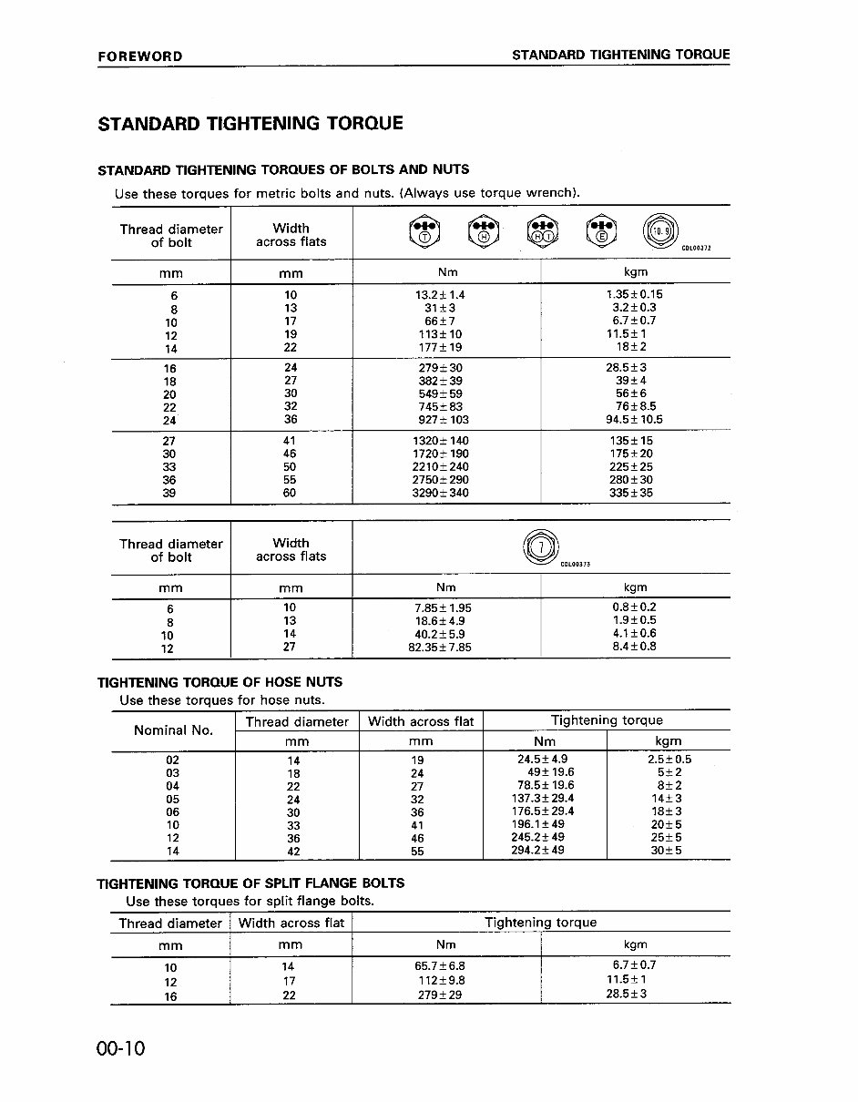
FOREWORD STANDARD TIGHTENING TORQUE STANDARD TIGHTENING TORQUE STANDARD TIGHTENING TORQUES OF BOLTS AND NUTS Use these torques for metric bolts and nuts. (Always use torque wrench). Thread diameter of bolt Width across flats I I mm mm Nm 6 10 13.2+1.4 1.3550.15 8 13 31f3 3.2&0.3 10 17 66f7 6.7k0.7 12 19 113flO 11.5*1 14 22 177+19 18k2 16 24 279+30 28.5?3 18 27 382f39 39k4 20 30 549f59 56f6 22 32 745f83 76k8.5 24 36 927f103 94.5* 10.5 27 41 1320+140 135k15 30 46 1720+190 175k20 33 50 2210f240 225+25 36 55 2750f290 28Ok30 39 60 3290f340 335k35 Thread diameter Width of bolt across flats 0 0 7 CDL00373 mm mm Nm kgm 6 10 7.85+ 1.95 0.8k0.2 8 13 18.6f4.9 1.9*0.5 10 14 40.2+5.9 4.1kO.6 12 27 82.35k7.85 8.4f0.8 TIGHTENING TORQUE OF HOSE NUTS Use these torques for hose nuts. Nominal No. Thread diameter Width across flat Tightening torque mm mm Nm kgm 02 14 19 24.5+4.9 2.5f0.5 03 18 24 49f 19.6 5+2 04 22 27 78.5f 19.6 8+2 05 24 32 137.3f29.4 14+3 06 30 36 176.5f29.4 18f3 10 33 41 196.lf49 20+5 12 36 46 245.2f49 25+5 14 42 55 294.2f49 3Ok5 TIGHTENING TORQUE OF SPLIT FLANGE BOLTS Use these torques for split flange bolts. Thread diameter Width across flat Tightening torque mm mm Nm k9m 10 14 65.756.8 6.7kO.7 17 17 112f9.8 11.5fl is 22 279f29 28.5f3 00-l 0
This is a comprehensive Service Shop Repair Manual for the KOMATSU PC200-6 HYDRAULIC EXCAVATOR. It contains detailed information about maintenance, assembly, disassembly, and servicing of your KOMATSU PC200-6 HYDRAULIC EXCAVATOR.
MACHINE MODEL SERIAL NUMBERS
PC200-6 - C10001 and up
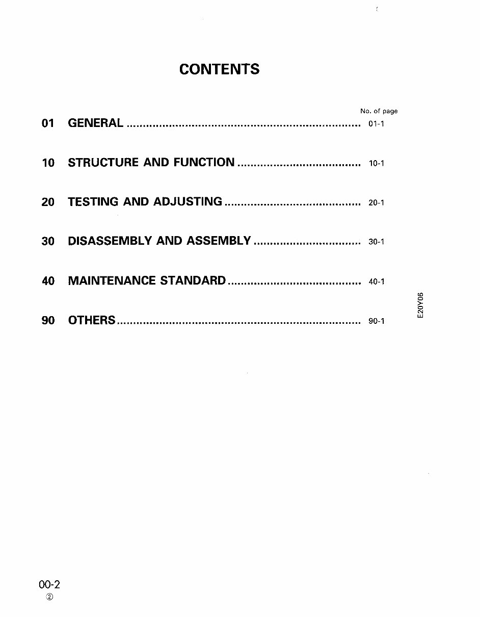
The contents are as follows:
01 GENERAL
10 STRUCTURE AND FUNCTION
20 TESTING AND ADJUSTING
30 DISASSEMBLY AND ASSEMBLY
40 MAINTENANCE STANDARD
90 OTHERS
Model Specification: KOMATSU PC200-6 HYDRAULIC EXCAVATOR
Language: English
File Format: .PDF
Total Pages: 531
Requirements: Adobe Reader
ZOOM IN/OUT: YES
Printable: YES
Compatible: All Versions of Windows & Mac
This manual contains information, data, specs, diagrams, actual real photo illustrations, and schemes, providing complete step-by-step operations on repair, servicing, technical maintenance, and troubleshooting procedures for your machine. It offers full information needed for repairing your machine and enables you to find trouble and understand how to repair and maintain your machine without going into service.
All manuals are Windows Vista32 and 64, XP, ME, 98, NT, 2000 compatible and work with Mac.
Instant access upon receipt of your payment.
Tons of pictures and diagrams are included for easy reference. All pages are printable, allowing you to run off what you need and take it with you into the garage or workshop. Save money by doing your own repairs with these very easy to follow, step-by-step instructions.
Recently Viewed
5,521,897Happy Clients
2,594,462eManuals
1,120,453Trusted Sellers
15Years in Business
Price:
Actual Price:
KOMATSU PC200-6 Hydraulic Excavator Service Shop Repair Manual (S/N: C10001 and up)

")