00-2 CONTENTS 01 GENERAL ............................................................................................................ 01-1 10 STRUCTURE AND FUNCTION .......................................................... 10-1 20 TESTING AND ADJUSTING ................................................................ 20-1 30 DISASSEMBLY AND ASSEMBLY .................................................... 30-1 40 MAINTENANCE STANDARD .............................................................. 40-1 90 OTHERS ............................................................................................................... 90-1 No. of page
5 00-2-1 PC128UU-1
00-2-2 PC128UU-1 5
5 00-2-3 PC128UU-1
00-2-4 PC128UU-1 5
00-3 GENERAL PRECAUTIONS Mistakes in operation are extremely dangerous. Read the Operation and Maintenance Manual carefully BEFORE operating the machine. 1. Before carrying out any greasing or repairs, read all the precautions given on the decals which are fixed to the machine. 2. When carrying out any operation, always wear safety shoes and helmet. Do not wear loose work clothes, or clothes with buttons missing. • Always wear safety glasses when hitting parts with a hammer. • Always wear safety glasses when grind- ing parts with a grinder, etc. 3. If welding repairs are needed, always have a trained, experienced welder carry out the work. When carrying out welding work, al- ways wear welding gloves, apron, hand shield, cap and other clothes suited for weld- ing work. 4. When carrying out any operation with two or more workers, always agree on the oper- ating procedure before starting. Always in- form your fellow workers before starting any step of the operation. Before starting work, hang UNDER REPAIR signs on the controls in the operator's compartment. 5. Keep all tools in good condition and learn the correct way to use them. 6. Decide a place in the repair workshop to keep tools and removed parts. Always keep the tools and parts in their correct places. Always keep the work area clean and make sure that there is no dirt or oil on the floor. Smoke only in the areas provided for smok- ing. Never smoke while working. PREPARATIONS FOR WORK 7. Before adding oil or making any repairs, park the machine on hard, level ground, and block the wheels or tracks to prevent the machine from moving. 8. Before starting work, lower blade, ripper, bucket or any other work equipment to the ground. If this is not possible, insert the safety pin or use blocks to prevent the work equipment from falling. In addition, be sure to lock all the control levers and hang warn- ing signs on them. 9. When disassembling or assembling, support the machine with blocks, jacks or stands before starting work. 10. Remove all mud and oil from the steps or other places used to get on and off the ma- chine. Always use the handrails, ladders or steps when getting on or off the machine. Never jump on or off the machine. If it is impossible to use the handrails, ladders or steps, use a stand to provide safe footing. Proper service and repair is extremely important for safe machine operation. The service and repair techniques recommended by Komatsu and described in this manual are both effective and safe. Some of these techniques require the use of tools specially designed by Komatsu for the specific purpose. To prevent injury to workers, the symbol ¤ is used to mark safety precautions in this manual. The cautions accompanying these symbols should always be followed care- fully. If any dangerous situation arises or may possibly arise, first consider safety, and take the necessary actions to deal with the situation. SAFETY SAFETY NOTICE IMPORTANT SAFETY NOTICE SAFETY SAFETY NOTICE
00-4 PRECAUTIONS DURING WORK 11. When removing the oil filler cap, drain plug or hydraulic pressure measuring plugs, loosen them slowly to prevent the oil from spurting out. Before disconnecting or removing compo- nents of the oil, water or air circuits, first remove the pressure completely from the circuit. 12. The water and oil in the circuits are hot when the engine is stopped, so be careful not to get burned. Wait for the oil and water to cool before carrying out any work on the oil or water circuits. 13. Before starting work, remove the leads from the battery. Always remove the lead from the negative (–) terminal first. 14. When raising heavy components, use a hoist or crane. Check that the wire rope, chains and hooks are free from damage. Always use lifting equipment which has ample capacity. Install the lifting equipment at the correct places. Use a hoist or crane and operate slowly to prevent the component from hit- ting any other part. Do not work with any part still raised by the hoist or crane. 15. When removing covers which are under in- ternal pressure or under pressure from a spring, always leave two bolts in position on opposite sides. Slowly release the pres- sure, then slowly loosen the bolts to remove. 16. When removing components, be careful not to break or damage the wiring. Damaged wiring may cause electrical fires. 17. When removing piping, stop the fuel or oil from spilling out. If any fuel or oil drips onto the floor, wipe it up immediately. Fuel or oil on the floor can cause you to slip, or can even start fires. 18. As a general rule, do not use gasoline to wash parts. In particular, use only the mini- mum of gasoline when washing electrical parts. 19. Be sure to assemble all parts again in their original places. Replace any damaged parts with new parts. • When installing hoses and wires, be sure that they will not be damaged by contact with other parts when the machine is be- ing operated. 20. When installing high pressure hoses, make sure that they are not twisted. Damaged tubes are dangerous, so be extremely care- ful when installing tubes for high pressure circuits. Also, check that connecting parts are correctly installed. 21. When assembling or installing parts, always use the specified tightening torques. When installing protective parts such as guards, or parts which vibrate violently or rotate at high speed, be particularly careful to check that they are installed correctly. 22. When aligning two holes, never insert your fingers or hand. Be careful not to get your fingers caught in a hole. 23. When measuring hydraulic pressure, check that the measuring tool is correctly assem- bled before taking any measurements. 24. Take care when removing or installing the tracks of track-type machines. When removing the track, the track sepa- rates suddenly, so never let anyone stand at either end of the track. SAFETY SAFETY NOTICE
00-5 NOTICE STRUCTURE AND FUNCTION This section explains the structure and function of each component. It serves not only to give an understanding of the structure, but also serves as reference material for troubleshooting. TESTING AND ADJUSTING This section explains checks to be made before and after performing repairs, as well as adjustments to be made at completion of the checks and repairs. Troubleshooting charts correlating "Problems" to "Causes" are also included in this section. DISASSEMBLY AND ASSEMBLY This section explains the order to be followed when removing, installing, disassembling or assembling each component, as well as precautions to be taken for these operations. MAINTENANCE STANDARD This section gives the judgement standards when inspecting disassembled parts. The specifications contained in this shop manual are subject to change at any time and without any advance notice. Use the specifications given in the book with the latest date. FOREWORD GENERAL This shop manual has been prepared as an aid to improve the quality of repairs by giving the serviceman an accurate understanding of the product and by showing him the correct way to perform repairs and make judgements. Make sure you understand the contents of this manual and use it to full effect at every opportunity. This shop manual mainly contains the necessary technical information for operations performed in a service workshop. For ease of understanding, the manual is divided into the following chapters; these chapters are further divided into the each main group of components. FOREWORD GENERAL
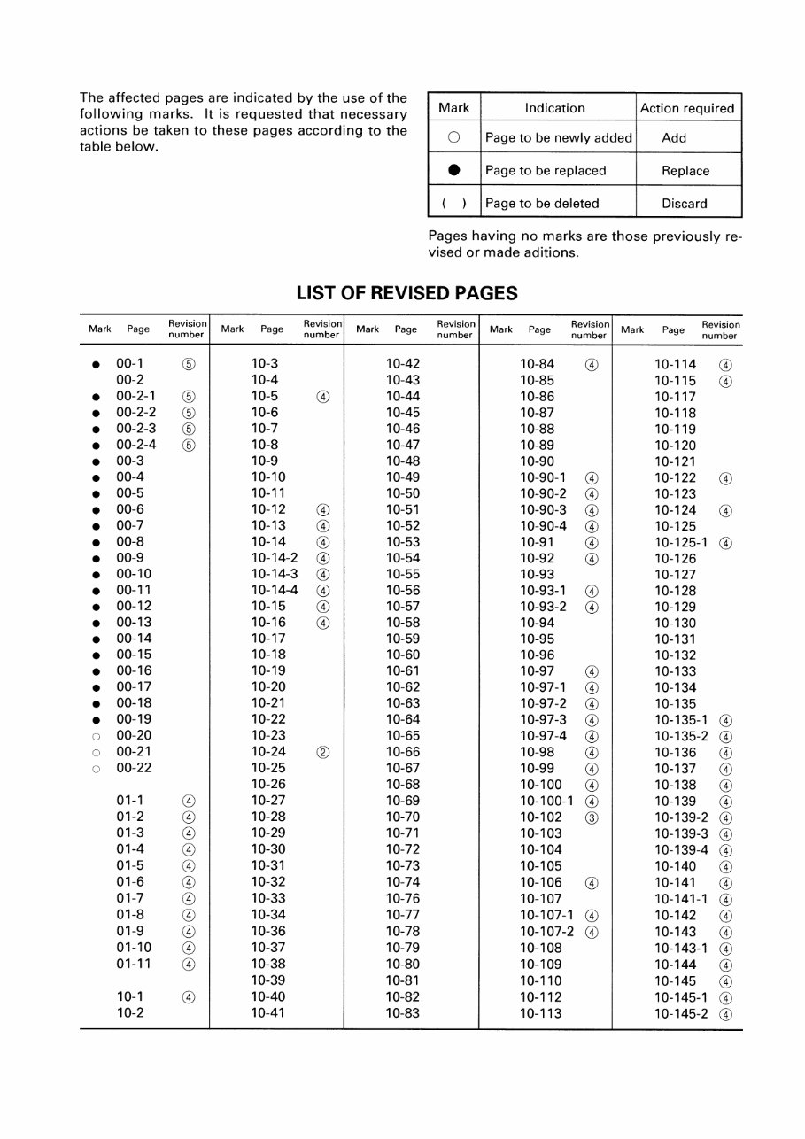
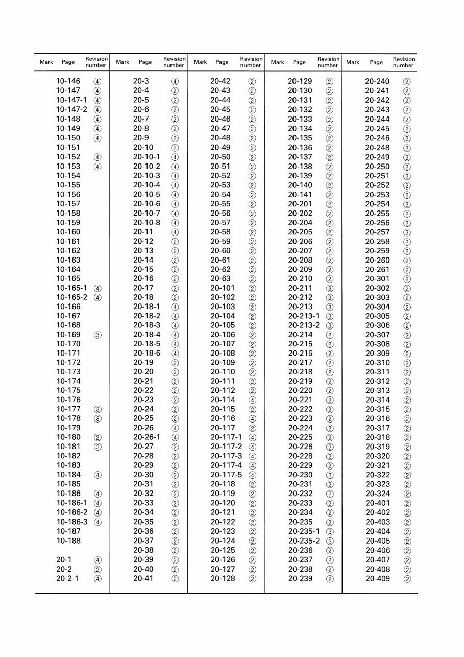
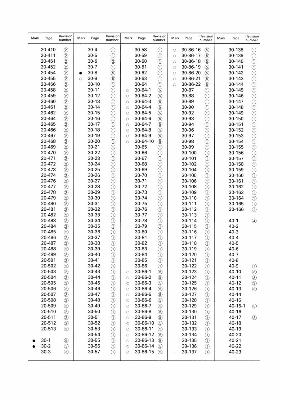
00-6 Shop manuals are issued as a guide to carrying out repairs. They are divided as follows: Chassis volume: Issued for every machine model Engine volume: Issued for each engine series Electrical volume: Attachments volume: These various volumes are designed to avoid duplicating the same information. Therefore, to deal with all repairs for any model , it is neces- sary that chassis, engine, electrical and attach- ment volumes be available. DISTRIBUTION AND UPDATING Any additions, amendments or other changes will be sent to KOMATSU distributors. Get the most up-to-date information before you start any work. FILING METHOD 1. See the page number on the bottom of the page. File the pages in correct order. 2. Following examples show how to read the page number. Example 1 (Chassis volume): 10 - 3 Item number (10. Structure and Function) Consecutive page number for each item. Example 2 (Engine volume): 12 - 5 Unit number (1. Engine) Item number (2. Testing and Adjusting) Consecutive page number for each item. 3. Additional pages: Additional pages are indi- cated by a hyphen (-) and number after the page number. File as in the example. Example: 10-4 10-4-1 10-4-2 10-5 VOLUMES Each issued as one volume to cover all models 12-203 12-203-1 12-203-2 12-204 Added pages REVISED EDITION MARK When a manual is revised, an edition mark (123....) is recorded on the bottom of the pages. REVISIONS Revised pages are shown in the LIST OF RE- VISED PAGES next to the CONTENTS page. SYMBOLS So that the shop manual can be of ample prac- tical use, important safety and quality portions are marked with the following symbols. Symbol Item Safety Caution Weight Tightening torque Coat Oil, water Drain Remarks Places where oil or water must be drained, and quan- tity to be drained. Places where oil, water or fuel must be added, and the ca- pacity. Places to be coated with ad- hesives and lubricants, etc. Places that require special at- tention for the tightening torque during assembly. Weight of parts of systems. Caution necessary when se- lecting hoisting wire, or when working posture is important, etc. Special technical precautions or other precautions for pre- serving standards are neces- sary when performing the work. Special safety precautions are necessary when performing the work. ¤ 4 3 2 5 6 fl } HOW TO READ THE SHOP MANUAL FOREWORD HOW TO READ THE SHOP MANUAL
Complete OEM service & repair manual for the Komatsu PC128UU-1/PC128US-1 Hydraulic Excavators (PC128UU-1: s/n 2347 and up; PC128US-1: s/n 1715 and up). No shipping involved – instant delivery so you can access it right away!
This comprehensive shop manual provides all the essential information needed to service and repair your excavator. It is ideal for both professional mechanics and DIY enthusiasts, offering detailed step-by-step procedures that empower you to save money by performing maintenance and repairs yourself.
OEM specifications and model details for Komatsu PC128UU-1/PC128US-1 Hydraulic Excavators
Clear repair instructions and troubleshooting procedures
Step-by-step illustrations and technical diagrams
Digital Adobe Acrobat format compatible with both PC and Mac
You can easily print the specific sections you require or print the entire manual and organize it in 3-ring binders for ongoing reference. If you are looking for a particular service manual from our extensive catalog, simply message us for assistance.
Instant digital delivery ensures that there’s no waiting for a CD or physical media to arrive via postal service. Get your manual immediately and start your repair work!
*Note: This manual is delivered digitally. Users with high-speed internet will experience the best performance since some files are large in size. Dial-up users should please contact us to confirm file compatibility.
Recently Viewed
5,521,897Happy Clients
2,594,462eManuals
1,120,453Trusted Sellers
15Years in Business
Price:
Actual Price:
Komatsu PC128UU-1/PC128US-1 Hydraulic Excavators OEM Service & Repair Manual