9803/6410 Issue 1 Introduction This publication is designed for the benefit of JCB Distributor Service Engineers who are receiving, or have received, training by JCB Technical Training Department. These personnel should have a sound knowledge of workshop practice, safety procedures, and general techniques associated with the maintenance and repair of hydraulic earthmoving equipment. Renewal of oil seals, gaskets, etc., and any component showing obvious signs of wear or damage is expected as a matter of course. It is expected that components will be cleaned and lubricated where appropriate, and that any opened hose or pipe connections will be blanked to prevent excessive loss of hydraulic fluid and ingress of dirt. Finally, please remember above all else SAFETY MUST COME FIRST! The manual is compiled in sections, the first three are numbered and contain information as follows: 1 = General Information - includes torque settings and service tools. 2 = Care & Safety - includes warnings and cautions pertinent to aspects of workshop procedures etc. 3 = Routine Maintenance - includes service schedules and recommended lubricants for the whole machine. The remaining sections are alphabetically coded and deal with Dismantling, Overhaul etc. of specific components, for example: A = Attachments B = Body & Framework ...etc The page numbering in each alphabetically coded section is not continuous. This allows for the insertion of new items in later issues of the manual. Section contents, technical data, circuit descriptions, operation descriptions etc. are inserted at the beginning of each alphabetically coded section. All sections are listed on the front cover; tabbed divider cards align directly with individual sections on the front cover for rapid reference. Where a torque setting is given as a single figure it may be varied by plus or minus 3%. Torque figures indicated are for dry threads, hence for lubricated threads may be reduced by one third. ‘Left Hand’ and ‘Right Hand’ are as viewed from the rear of the machine facing forwards. Note: In this manual the term ‘swing’ may sometimes be used in place of ‘slew’ and the term ‘arm’ may sometimes be used in place of ‘dipper’.
Contents Page No. Bolt and Nut Torque Specifications 1 - 1 Torque Settings 1 - 2 Service Tools * Section B - Body and framework 3 - 1 Section C - Electrics 4 - 1 Section E - Hydraulics 5 - 1 * Section F - Transmission 6 - 1 *Sealing and Retaining Compounds 7 - 1 i General Information 9803/6410 i Issue 2* Section 1 Section 1
1 - 1 Section 1 General Information 9803/6410 Section 1 1 - 1 Issue 2* Bolt and Nut Torque Specifications JS130/JS160 and Variants Tighten the bolts and nuts according to the table. Before and after daily work, check the bolts and nuts for looseness and for those missing. Tighten if loose and renew if missing. Tighten the bolts and nuts after the first 50 hours of the running-in stage and every 250 hours thereafter. Tightening Torque Table Note: Use JCB Threadlocker and Sealer (High Strength) (adhesive) on those marked † and tighten to the torque listed in the above table. The tightening torques for the bolts and nuts not listed above are as follows: JS130/JS160 No Tightening Point Bolt Diameter Wrench Tightening Torque mm Nm kgf m lbf ft 1† Travel Motor M16 24 270~310 27.6~31.8 200~230 2† Drive Sprocket M16 24 220~310 27.6~31.8 200~230 3† Idler Wheel M16 24 270~310 27.6~31.8 200~230 4† Upper (Carrier) Roller M16/M20 24/30 270~310/520~608 27.6~31.8/53.2~62.2 200~230/385~450 5† Lower (Track) Roller M16 24 270~310 27.6~31.8 200~230 6† Track Guard M16 24 270~310 27.6~31.8 200~230 7 Shoe Bolt M16 24 310~360/640~750 32~37/65~76.5 229~266/472~553 8 Counter weight M27 41 845~980 86~100 622~723 9† Turntable Bearing (Undercarriage) M16/M20 24 280~310/475~550 28.4~31.8/48.4~55.3 205~230/350~400 10† Turntable Bearing (Slew Frame) M16/M20 24 280~310/475~550 28.4~31.8/48.4~55.3 205~230/350~400 11† Slew Equipment M16/M20 24 280~310/475~550 28.4~31.8/48.4~55.3 205~230/350~440 12† Engine (Engine Mount) M16 24 265~310 27~32 195~230 13† Engine Bracket M10 17 65~75 6.5~7.6 47~55 14 Radiator M12 19 60~70 6.2~7.2 45~52 15† Hydraulic Pump M10 17 65~75 6.5~7.6 47~55 16† Hydraulic Oil Tank M16 24 205~285 21~29 152~210 17† Fuel Tank M16 24 225~285 22.4~29 162~210 18† Control Valve M16 24 270~310 27.6~31.8 200~230 19† Rotary Coupling M12 19 110~125 11.1~13.0 80~94 20 Cab M16 24 127~137 13~14 94~101 21 Battery M10 17 20~30 2.1~2.9 15~21 Bolt Diameter (size) M6 M8 M10 M12 M14 M16 M18 M20 Wrench mm 10 13 17 19 22 24 27 30 Hex. bolt Tightening Nm 6.9 15.7 32.3 58.8 98.0 137.2 196.0 274.4 Torque kgf m 0.7 1.6 3.2 5.9 9.8 13.7 19.6 27.4 lbf ft 5 12 24 43 72 101 145 202 Wrench mm 5 6 8 10 12 14 14 17 Hex. socket head Tightening Nm 8.8 21.6 42.1 78.4 117.6 176.4 245.0 343.0 bolt Torque kgf m 0.88 2.2 4.2 7.8 11.8 17.6 24.5 34.3 lbf ft 6.5 16 31 58 87 130 181 253 * *
1 - 2 Section 1 General Information 9803/6410 Section 1 1 - 2 Issue 1 Torque Settings Torque Settings Note 1: The figures quoted are for non-plated fasteners and are to be used only when there is no torque setting specified in the relevant procedure in this service manual. Note 2: The 4T grade settings DO NOT APPLY to fasteners used on the engine. If any 4T specification fasteners are found on the engine, these must be tightened to the figure quoted in the relevant engine manual. Bolt Size Strength Grade of Bolt or Stud 4T 8.8 10.9 Nm kgf m lbf ft Nm kgf m lbf ft Nm kgf m lbf ft M3 0.39 0.04 0.28 - - - - - - M4 0.78 0.08 0.57 - - - - - - M5 1.67 0.17 1.2 - - - - - - M6 2.84 0.29 2.1 8.04 0.82 5.9 11.3 1.15 8.3 M8 7.06 0.72 5.2 19.6 2.00 14.5 27.7 2.82 20.4 M10 14.0 1.43 10.3 39.1 3.99 28.8 55.0 5.61 40.6 M12 24.6 2.51 18.1 68.5 6.98 50.5 96.2 9.81 71 M16 61.9 6.31 45.7 173 17.6 127.6 242 24.7 178.5 M20 122 12.4 90 337 34.4 249 475 48.4 350 M22 167 17.0 123 464 47.3 342 652 66.5 481 M24 210 21.4 155 584 59.5 431 821 83.7 606 M27 311 31.7 229 864 88.1 637 1220 124 900 M30 420 42.8 310 1170 119 863 1650 168 1217 M33 576 58.7 425 1600 163 1180 2260 230 1667 M36 736 75.1 543 2050 209 1512 2880 294 2124 M39 961 98.0 709 2680 273 1977 3760 383 2773 M42 1190 121 878 3300 336 2434 4640 473 3422 M45 1490 152 1099 4140 422 3054 5820 593 4293 M48 1780 182 1312 4960 506 3659 6970 711 5141
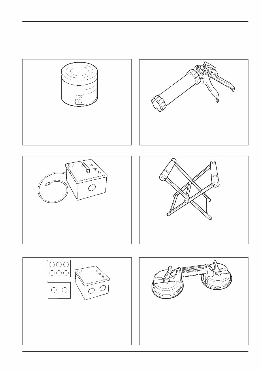
3 - 1 Section 1 General Information 9803/6410 Section 1 3 - 1 Issue 1 Service Tools (SECTION B) BODY AND FRAMEWORK S186240 Hand Cleaner - special blend for the removal of polyurethane adhesives. 4104/1310 (454g; 1lb tub) S186250 12V Mobile Oven - 1 cartridge capacity - required to pre-heat adhesive prior to use. It is fitted with a male plug (703/23201) which fits into a female socket (715/04300). 992/12300 S186260 240V Static Oven - available with 2 or 6 cartridge capacity - required to pre-heat adhesive prior to use. No plug supplied. Note: 110V models available upon request - contact JCB Technical Service 992/12400 - 2 cartridge x 240V 992/12600 - 6 cartridge x 240V S186270 Cartridge Gun - hand operated - essential for the application of sealants, polyurethane materials etc. 892/00845 ' S186280 Folding Stand for Holding Glass - essential for preparing new glass prior to installation. 892/00843 S186300 Glass Lifter - minimum 2 off - essential for glass installation, 2 required to handle large panes of glass. Ensure suction cups are protected from damage during storage. 892/00842
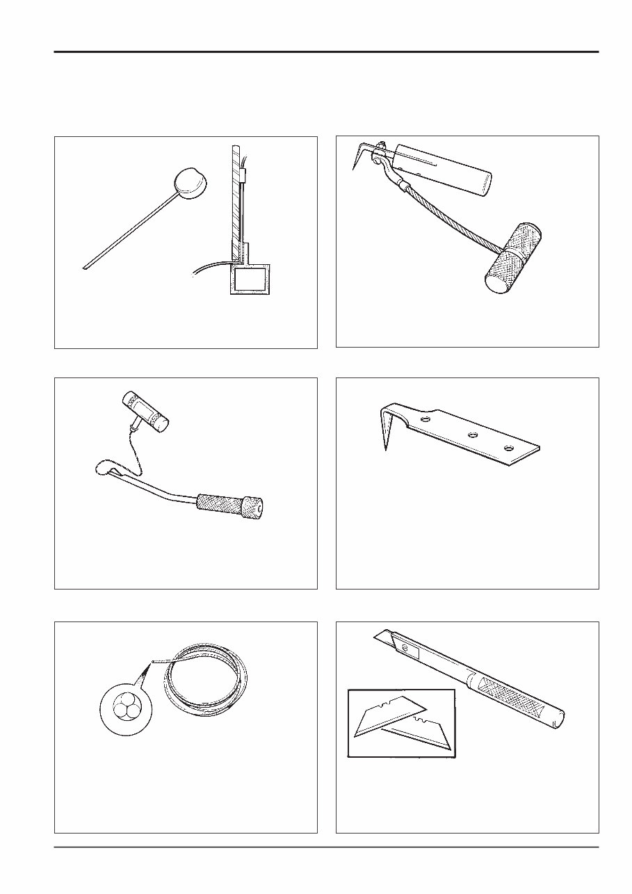
Service Tools (cont’d) (SECTION B) BODY AND FRAMEWORK S186310 Wire Starter - used to access braided cutting wire (below) through original polyurethane seal. 892/00848 S186320 Glass Extractor (Handles) - used with braided cutting wire (below) to cut out broken glass. 892/00846 S186330 Braided Cutting Wire - consumable heavy duty cut-out wire used with the glass extraction tool (above). 892/00849 (approx 25m length) S186340 Cut-out Knife - used to remove broken glass. 992/12800 ' S186350 'L' Blades - 25mm (1in.) cut - replacement blades for cut-out knife (above). 992/12801 (unit quantity = 5 off) S186360 Long Knife - used to give extended reach for normally inaccessible areas. 892/00844 3 - 2 Section 1 General Information 9803/6410 Section 1 3 - 2 Issue 1
Service Tools (cont’d) (SECTION B) BODY AND FRAMEWORK S186470 Nylon Spatula - general tool used for smoothing sealants - also used to re-install glass in rubber glazing because metal tools will chip the glass edge. 892/00847 S186550 Rubber Spacer Blocks - used to provide the correct set clearance between glass edge and cab frame. 926/15500 (unit quantity = 500 off) 3 - 3 Section 1 General Information 9803/6410 Section 1 3 - 3 Issue 1
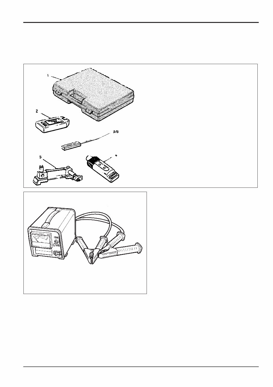
4 - 1 Section 1 General Information 9803/6410 Section 1 4 - 1 Issue 2* Service Tools SECTION C - ELECTRICS Electrical Test Equipment 1 892/00283 Tool Kit Case 2 892/00281 AVO Meter 3 892/00286 Surface Temperature Probe 4 892/00284 Microtach Digital Tachometer 5 892/00282 Shunt - open type 6 892/00285 Hydraulic Oil Temperature Probe 7 892/00298 Fluke 85 Multimeter 993/85700 Battery Tester
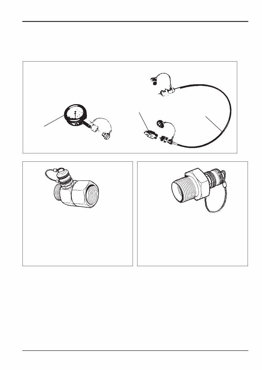
Service Tools (continued) SECTION E - HYDRAULICS 5 - 1 Section 1 General Information 9803/6410 Section 1 5 - 1 Issue 2* Pressure Test ‘T’ Adapters 892/00262 1/4 in BSP x 1/4 in F BSP x Test Point 816/55038 3/8 in BSP x 3/8 in F BSP x Test Point 816/55040 1/2 in BSP x 1/2 in F BSP x Test Point 892/00263 5/8 in BSP x 5/8 in F BSP x Test Point 892/00264 3/4 in BSP x 3/4 in F BSP x Test Point 892/00265 1 in M BSP x 1 in F BSP x Test Point 892/00266 1,1/4 in M BSP x 1,1/4 in F BSP x Test Point 892/00267 1,1/2 in M BSP x 1,1/2 in F BSP x Test Point Pressure Test Adapters 892/00255 1/4 in BSP x Test Point 892/00256 3/8 in BSP x Test Point 892/00257 1/2 in BSP x Test Point 892/00258 5/8 in BSP x Test Point 816/15118 3/4 in BSP x Test Point 892/00259 1 in BSP x Test Point 892/00260 1,1/4 in BSP x Test Point 892/00261 5/8 in UNF x Test Point Hydraulic Pressure Test Gauges and Connections 1 892/00279 Pressure Gauge 0-400 bar (0-6000 lbf/in 2 ) 2 892/00346 Pressure Gauge 0-70 bar (0-1000 lbf/in 2 ) 3 892/00347 Connector 4 892/00254 Hose 5 892/00280 Pressure Gauge 0-600 bar (0-9000 lbf/in 2 ) 1/2/5 3 4
JCB JS130 Tracked Excavator OEM Service & Repair Manual is a comprehensive guide containing detailed information for repairing, maintaining, rebuilding, refurbishing, or restoring the JCB JS130 Tracked Excavator. It covers diagnostic and repair procedures extensively, providing the same trusted information used by professional technicians and mechanics.
This manual is designed for both professional technicians and do-it-yourself mechanics, offering detailed repair procedures, scheduled maintenance information, wiring diagrams, and diagnostics. It includes:
Detailed sub steps that expand on repair procedure information
Notes, cautions, and warnings throughout each chapter to isolate critical details
Numbered instructions to guide you through every repair procedure step by step
Bold figure numbers to quickly match illustrations with instructions
Detailed illustrations, drawings, and photos to support every procedure
Enlarged insets to help you identify and examine parts in detail
Numbered table of contents for easy navigation
Troubleshooting and electrical service procedures combined with detailed wiring diagrams for ease of use
The OEM Service & Repair Manual is available in .PDF format and is compatible with all versions of Windows and Mac. It can be saved to your hard drive and printed, providing instant access without additional shipping costs or delays.
The manual covers a wide range of topics including general information, specifications, engine removal, wiring diagrams, lubrication points, oil types, periodic maintenance, tune-up procedures, disassembly, reassembly, fuel and lubrication systems, electrical system, chassis, suspension, servicing information, service data, tools, tightening torques, gearbox, exhaust system, and much more.
Whether you are a professional mechanic or a DIY enthusiast, the JCB JS130 Tracked Excavator OEM Service & Repair Manual delivers all the necessary information to effectively diagnose and repair problems with the machine's electrical system, engine, and various other components.
Recently Viewed
5,521,897Happy Clients
2,594,462eManuals
1,120,453Trusted Sellers
15Years in Business
Price:
Actual Price:
JCB JS130 Tracked Excavator OEM Service & Repair Manual