

IHI 7J Mini Excavator Parts Catalogue
What's Included?
Fast Download Speeds
Online & Offline Access
Access PDF Contents & Bookmarks
Full Search Facility
Print one or all pages of your manual
PARTS
MINI
7J
EXCAVATOR
SERIAL No. BR000001-
IHI
A
El I II!BS4B3%Srit+
IHI Construction Machinery Limited
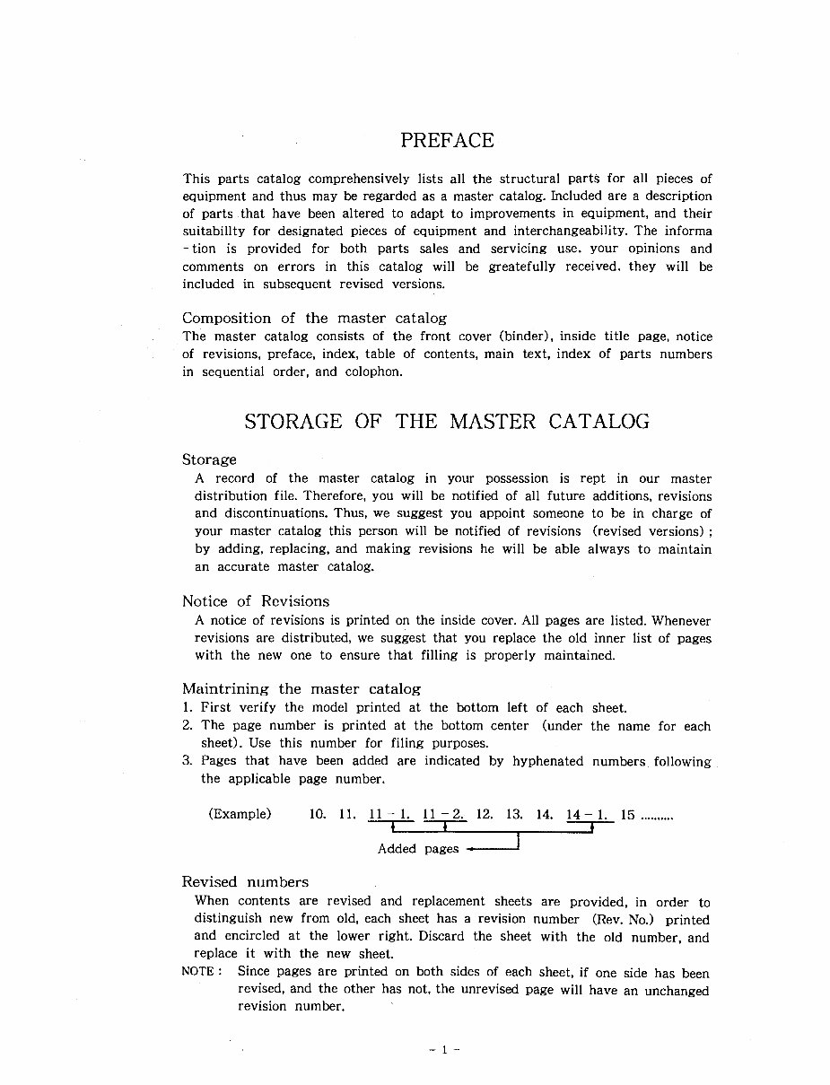
PREFACE
This parts catalog comprehensively lists all the structural parts for all pieces of
equipment and thus may be regarded as a master catalog. Included are a description
of parts that have been altered to adapt to improvements in equipment, and their
suitabillty for designated pieces of equipment and interchangeability. The informa
- tion is provided for both parts sales and servicing use. your opinions and
comments on errors in this catalog will be greatefully received. they will be
included in subsequent revised versions.
Composition of the master catalog
The master catalog consists of the front cover (binder), inside title page, notice
of revisions, preface, index, table of contents, main text, index of parts numbers
in sequential order, and colophon.
STORAGE THE MASTER CATALOG
Storage
A record of the master catalog in your possession is rept in our master
distribution file. Therefore, you will be notified of all future additions, revisions
and discontinuations. Thus, we suggest you appoint someone to be in charge of
your master catalog this person will be notified of revisions (revised versions) ;
by adding, replacing, and making revisions he will be able always to maintain
an accurate master catalog.
Notice of Revisions
A notice of revisions is printed on the inside cover. All pages are listed. Whenever
revisions are distributed, we suggest that you replace the old inner list of pages
with the new one to ensure that filling is properly maintained.
Maintrining the master catalog
1. First verify the model printed at the bottom left of each sheet.
2. The page number is printed at the bottom center (under the name for each
sheet). Use this number for filing purposes.
3. Pages that have been added are indicated by hyphenated numbers following
the applicable page number.
(Example) 10. 11. 11-1. 11-2. 12. 13. 14. 14-1. 15 ..........
-
Added pages
Revised numbers
When contents are revised and replacement sheets are provided, in order to
distinguish new from old, each sheet has a revision number (Rev. No.) printed
and encircled at the lower right. Discard the sheet with the old number, and
replace it with the new sheet.
NOTE : Since pages are printed on both sides of each sheet, if one side has been
revised, and the other has not, the unrevised page will have an unchanged
revision number.
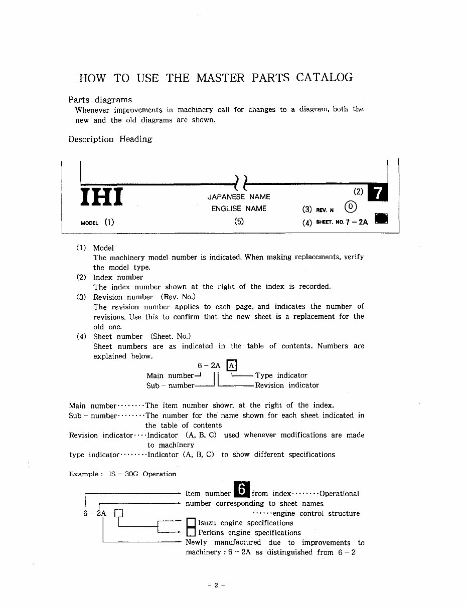
HOW TO USE THE MASTER PARTS CATALOG
Parts diagrams
Whenever improvements in machinery call for changes to a diagram, both the
new and the old diagrams are shown.
Description Heading
,
IHI
JAPANESE ENGLISE +-T,d NAME NAME (3) REV. N @
MODEL (1) (5) (4) SHEIT. NO. 7 - 2A
Model
The machinery model number is indicated. When making replacements, verify
the model type.
Index number
The index number shown at the right of the index is recorded.
Revision number (Rev. No.)
The revision number applies to each page, and indicates the number of
revisions. Use this to confirm that the new sheet is a replacement for the
old one.
Sheet number (Sheet. No.)
Sheet numbers are as indicated in the table of contents. Numbers are
explained below.
6-2A
Main number1 -Type indicator
Sub - number Revision indicator
Main number ........ The item number shown at the right of the index.
Sub - number ........ The number for the name shown for each sheet indicated in
the table of contents
Revision indicator. .Indicator (A, B, C) used whenever modifications are made
to machinery
type indicator. . -. .Indicator (A, B, C) to show different specifications
Example : IS - 30G Operation
I - Item number
from index- . . , . Operational
1 1
number corresponding to sheet names
P
...... engine control structure
Isuzu engine specifications
Perkins engine specifications
Newly manufactured due to improvements to
machinery : 6 - 2A as distinguished from 6 - 2
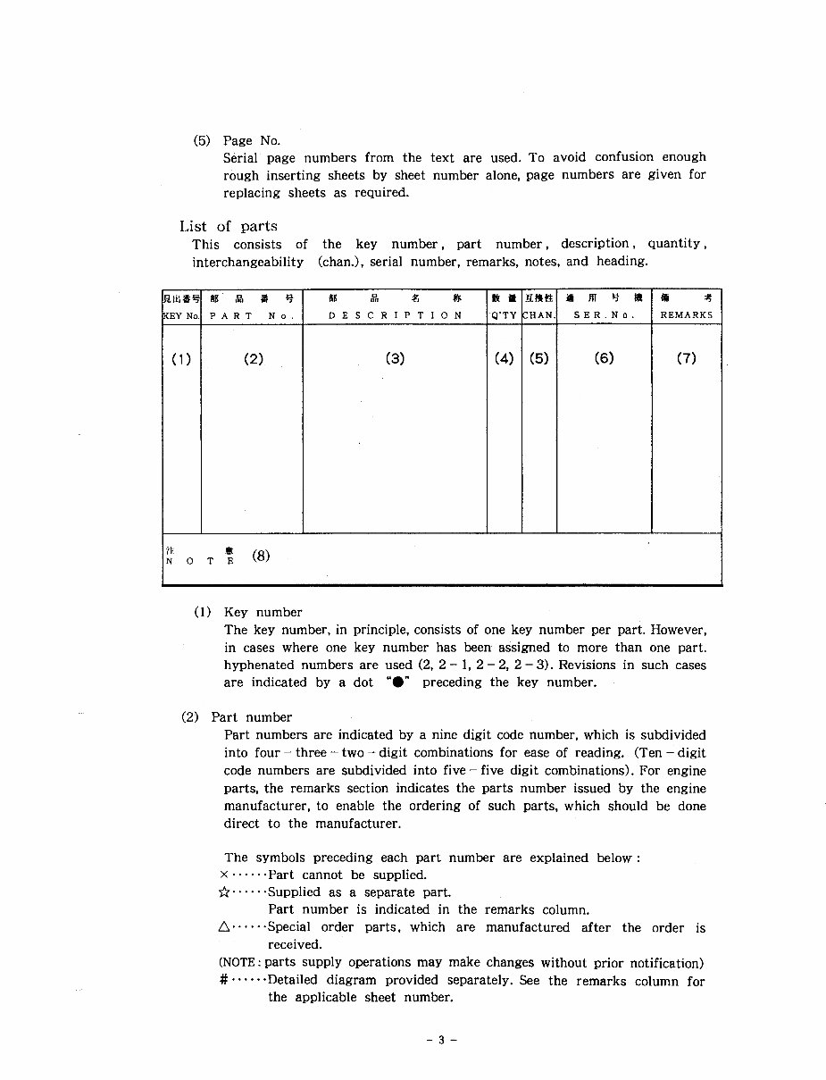
(5) Page No.
Serial page numbers from the text are used. To avoid confusion enough
rough inserting sheets by sheet number alone, page numbers are given for
replacing sheets as required.
List of parts
This consists of the key number, part number, description, quantity,
interchangeability khan.), serial number, remarks, notes, and heading.
P A R T No. D E S C R I P T I O N
ta t
REMARKS
(7)
(1) Key number
The key number, in principle, consists of one key number per part. However,
in cases where one key number has been assigned to more than one part.
hyphenated numbers are used (2, 2 - 1, 2 - 2, 2 - 3). Revisions in such cases
are indicated by a dot "a" preceding the key number.
(2) Part number
Part numbers are indicated by a nine digit code number, which is subdivided
into four - three - two - digit combinations for ease of reading. (Ten - digit
code numbers are subdivided into five - five digit combinations). For engine
parts, the remarks section indicates the parts number issued by the engine
manufacturer, to enable the ordering of such parts, which should be done
direct to the manufacturer.
The symbols preceding each part number are explained below :
x., .... Part cannot be supplied.
fi.. .. . . Supplied as a separate part.
Part number is indicated in the remarks column.
n...... Special order parts, which are manufactured after the order is
received.
(NOTE: parts supply operations may make changes without prior notification)
#...... Detailed diagram provided separately. See the remarks column for
the applicable sheet number.
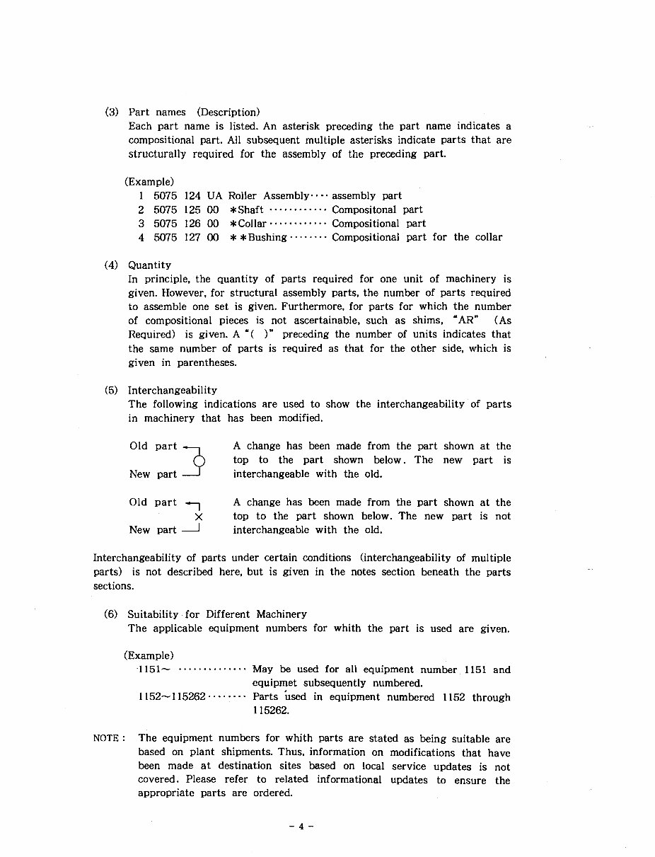
Part names (Description)
Each part name is listed. An asterisk preceding the part name indicates a
compositional part. All subsequent multiple asterisks indicate parts that are
structurally required for the assembly of the preceding part.
(Example)
1 5075 124 UA Roller Assembly.. . assembly part
2 5075 125 00 *Shaft ............ Compositonal part
3 5075 126 00 *Collar- ........... Compositional part
4 5075 127 00 **Bushing ........ Compositional part for the collar
Quantity
In principle. the quantity of parts required for one unit of machinery is
given. However. for structural assembly parts, the number of parts required
to assemble one set is given. Furthermore, for parts for which the number
of compositional pieces is not ascertainable, such as shims. "AR" (As
Required) is given. A "( )" preceding the number of units indicates that
the same number of parts is required as that for the other side, which is
given in parentheses.
Interchangeability
The following indications are used to show the interchangeability of parts
in machinery that has been modified.
A change has been made from the part shown at the Old part 3
top to the part shown below. The new part is
New part 1 interchangeable with the old.
Old part --, A change has been made from the part shown at the
X top to the part shown below. The new part is not
New part 1 interchangeable with the old.
Interchangeability of parts under certain conditions (interchangeability of multiple
parts) is not described here, but is given in the notes section beneath the parts
sections.
(6) Suitability. for Different Machinery
The applicable equipment numbers for whith the part is used are given.
(Example)
,1151- .............. May be used for all equipment number 1151 and
equipmet subsequently numbered.
1152-115262...... -. Parts k e d in equipment numbered 1152 through
115262.
NOTE : The equipment numbers for whith Parts are stated as being suitable are
based on plant shipments. Thus, information on modifications that have
been made at destination sites based on local service updates is not
covered. Please refer to related informational updates to ensure the
appropriate parts are ordered.
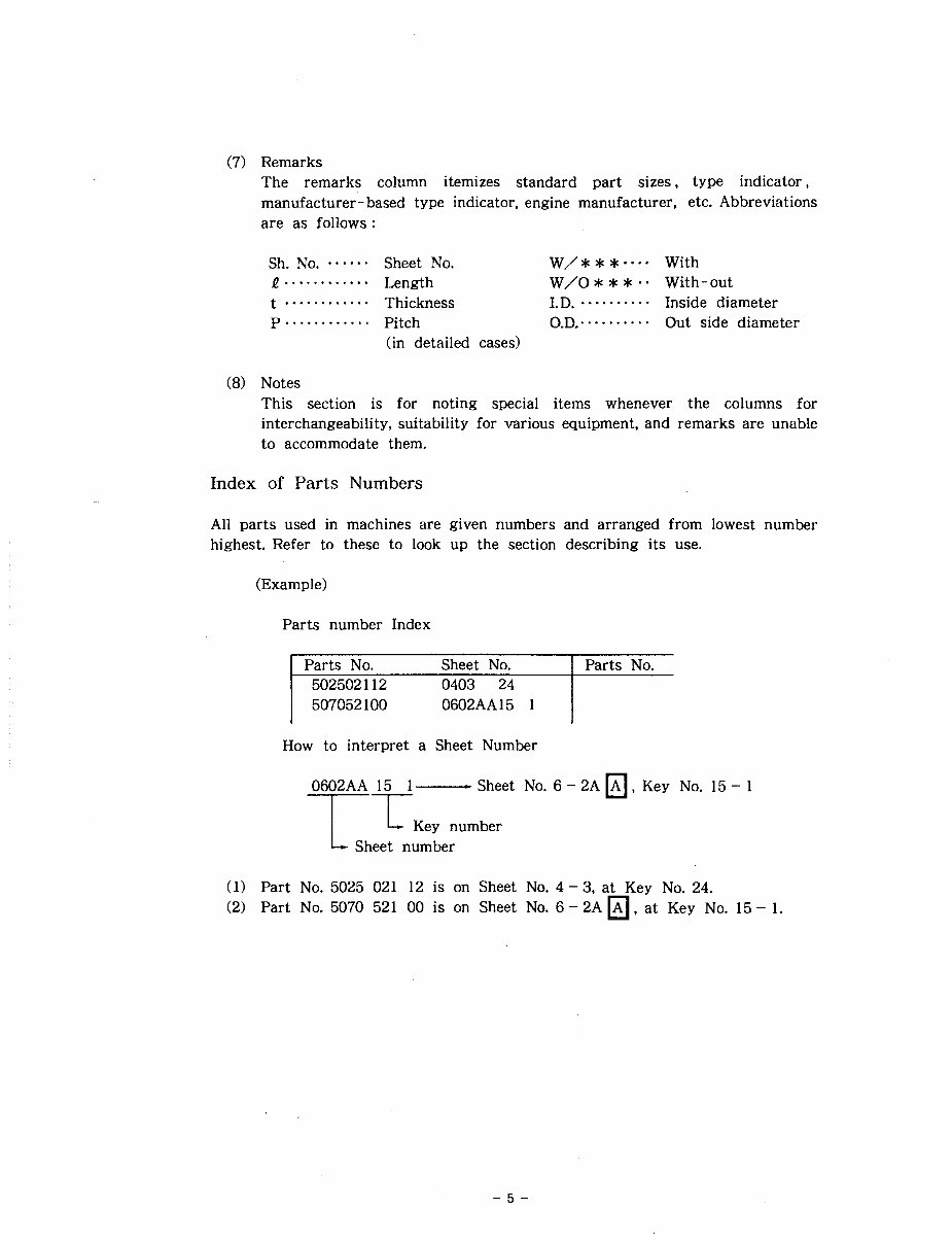
(7) Remarks
The remarks column itemizes standard part sizes, type indicator,
manufacturer-based type indicator, engine manufacturer, etc. Abbreviations
are as follows :
...... Sh. No. Sheet No. W/* * *..-. With
f ............
Length W/O*** -. With-out
.......... t ............ Thickness I.D. Inside diameter
p ............ .........
Pitch o.D.. Out side diameter
(in detailed cases)
(8) Notes
This section is for noting special items whenever the columns for
interchangeability, suitability for various equipment, and remarks are unable
to accommodate them.
Index of Parts Numbers
All parts used in machines are given numbers and arranged from lowest number
highest. Refer to these to look up the section describing its use.
(Example)
Parts number Index
I parts NO. Sheet No. 1 Parts No.
How to interpret a Sheet Number
0602AA 15 1 - Sheet No. 6 - 2A , Key No. 15 - 1
TI
L
Key number
Sheet number
(1) Part No. 5025 021 12 is on Sheet No. 4 - 3, at Key No. 24.
(2) Part No. 5070 521 00 is on Sheet No. 6 - 2A . at Key No. 15 - 1.
SECTION 1
LOWER MACHINE
IHI Construction Machinery Limited
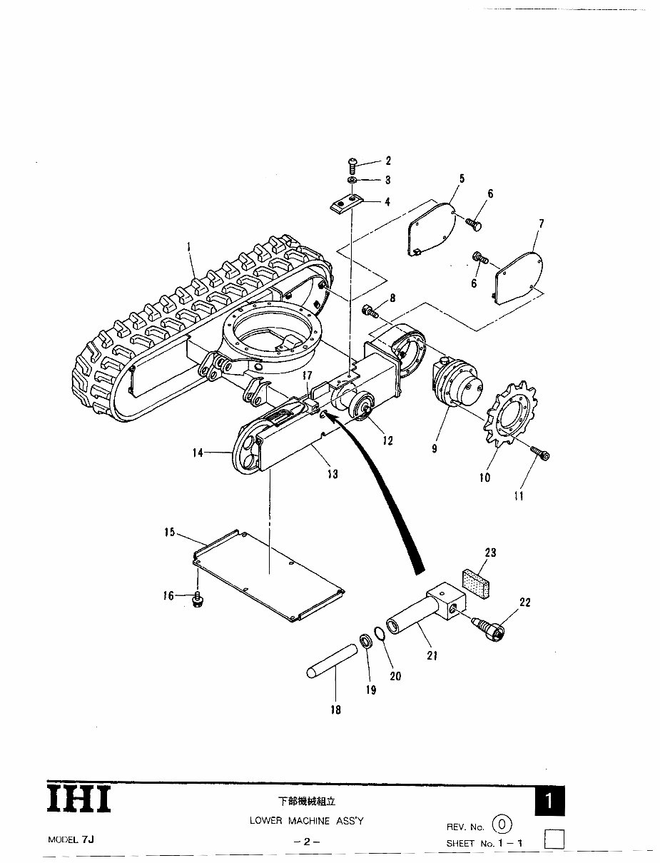
IHI T%#$@$B2
LOWER MACHINE ASS'Y
REV. No. @) -
MODEL 75 -2- SHEET No. 1 - 1
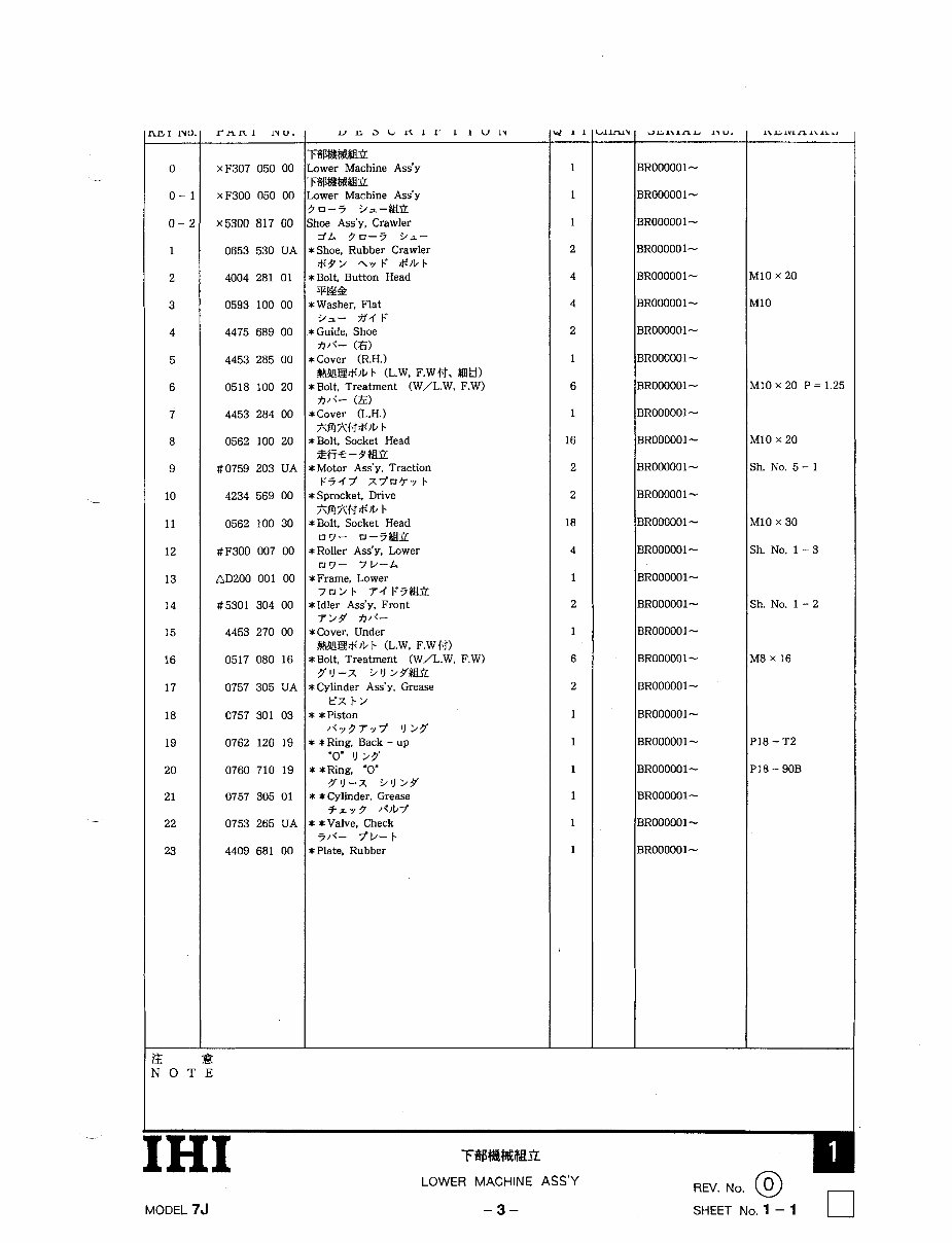
FblHrn
.ower Machine Ass'y
F%%Wli?
.ower Machine Ass'y
?0-4 >=-@it
;hoe Ass'y, Crawler
zth 30-4 91-
t Shoe. Rubber Crawler
*9> 4y F $)bb
t Bolt. Button Head
TEE&
t Washer, Flat
9a- A ' 4 F
t Guide, Shoe
A/<- (6)
t Cover (R.H.)
I@Elt;')b b (L.W. F.WH. $BE!)
tBolt. Treatment (W/L.W. F.W)
A/<-- (El
t Cover (L.H.)
*RZH*)b b
t Bolt, Socket Head
ZWe- 9M*
t Motor Ass'y. Traction
F44Y xY0'T.y b
t Sprocket, Drive
*RXH&)b b
t Bolt, Socket Head
07- 0-4@YL
t Roller Ass'y, Lower
07- 71/-4
t Frame. Lower
70>b 74F4-
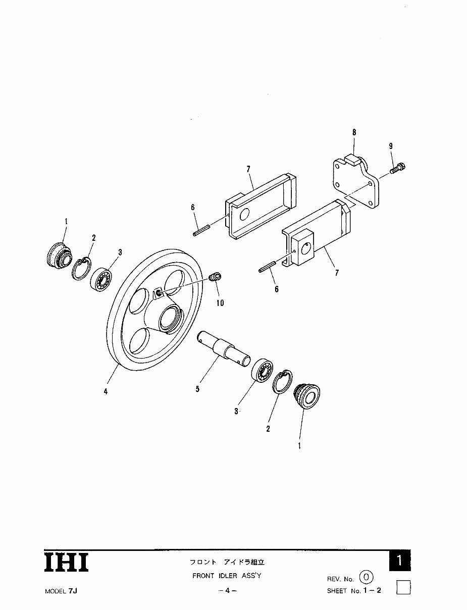
t Idler Ass'y. Front
7>++ A/<-
t Cover, Under
I @ E $ ) b b (L.W. F.W H)
tBolt. Treatment (W/L.W. F.W)
9.1)-X 31) >9'MiZ
t Cylinder Ass'y, Grease
tr'x b >
t *Piston
/t797Tj 1) 99'
t *Ring. Back - up
'0" 11 >9'
k *Ring, '0"
71)-X 3lJ>9'
k *Cylinder, Grease
4z.y 3 /<)by
F *Valve. Check
F/<- yp-b
t Plate, Rubber
BR00000 1 -
BR000001-
BR000001-
BR000001-
BR000001-
BROOOOO 1 -
BR000001-
BR000001-
BR000001-
BR000001-
BR000001-
BR00000 1 -
BR000001-
BR000001-
BR000001-
BR000001-
BR000001-
BR000001-
BR00000 1 -
BR000001-
BR000001-
BR000001-
BR000001-
BR000001-
BR000001-
BR000001-
110 x 20
410
dl0 x 20 P = 1.25
dl0 x 20
ih. No. 5 - 1
dl0 X 30
;h. No. 1 - 3
;h. No. 1 - 2
A8 x 16
'18 - T2
'18 - 9OB
[HI
MODEL 7J -3- SHEET No. 1 - 1 u
IHI
7 0 2 b 7-1 E.'T#Ra
FRONT IDLER ASS'Y REV. .o.Z
MODEL 75
-- 4 -
SHEET No. 1 - 2
You're Reading a Preview
What's Included?
Fast Download Speeds
Online & Offline Access
Access PDF Contents & Bookmarks
Full Search Facility
Print one or all pages of your manual
$36.99
Viewed 99 Times Today


Secure transaction
What's Included?
Fast Download Speeds
Online & Offline Access
Access PDF Contents & Bookmarks
Full Search Facility
Print one or all pages of your manual
$36.99
Looking to repair your IHI 7J MINI EXCAVATOR? Save on mechanic fees with our comprehensive parts manual, perfect for professional mechanics and DIY enthusiasts alike. This manual contains detailed information, including hundreds of images, illustrations, and blown-up diagrams, covering:
- Lower Machine
- Turntable
- Swing Drive Motor
- Hydraulic Piping
- Hydraulic Instrument
- Operating Controls
- Power Unit
- Cab & Related Parts
- Electric System
- Tools & Accessories
- Hoe Attachment
- Blade Attachments
- Special Parts
- And more...
This manual consists of 152 pages and is available in English format for Win/Mac compatibility. It provides instant access upon receipt of payment, allowing you to access numerous pictures and diagrams at your fingertips. All pages are printable, enabling you to take the necessary information with you wherever you go, without incurring shipping costs or waiting for a CD to arrive in the mail. Order now to start your repairs!


