

HITACHI ZAXIS 75US Excavator Full Service Repair Manual
What's Included?
Fast Download Speeds
Online & Offline Access
Access PDF Contents & Bookmarks
Full Search Facility
Print one or all pages of your manual

Technical Manual
(Operational Principle)
Vol No.: TO197E-00

INTRODUCTION
IN-01
TO THE READER
• This manual is written for an experienced technician
to provide technical information needed to maintain
and repair this machine.
• Be sure to thoroughly read this manual for correct
product information and service procedures.
• If you have any questions or comments, at if you
found any errors regarding the contents of this
manual, please contact using “Service Manual
Revision Request Form at the end of this man-
ual.
(Note: Do not tear off the form. Copy it for us-
age.):
Publications Marketing & Product Support
Hitachi Construction Machinery Co. Ltd.
TEL: 81-298-32-7173
FAX: 81-298-31-1162
ADDITIONAL REFERENCES
• Please refer to the materials listed below in addition
to this manual.
• The Operator’s Manual
• The Parts Catalog
• Operation Manual of the Engine
• Parts Catalog of the Engine
• Hitachi Training Material
MANUAL COMPOSITION
• This manual consists of three portions: the Techni-
cal Manual (Operational Principle), the Technical
Manual (Troubleshooting) and the Workshop Man-
ual.
• Information included in the Technical Manual
(Operational Principle):
technical information needed for redeliver and
delivery, operation and activation of all devices
and systems.
• Information included in the Technical Manual
(Troubleshooting):
technical information needed for operational per-
formance tests, and troubleshooting procedures.
• Information included in the Workshop Manual:
technical information needed for maintenance
and repair of the machine, tools and devices
needed for maintenance and repair, maintenance
standards, and removal/installation and assem-
ble/disassemble procedures.
PAGE NUMBER
• Each page has a number, located on the center
lower part of the page, and each number contains
the following information:
Example : T 1 -3 -5
Consecutive Page Number for Each Group
Group Number
Section Number
T: Technical Manual W: Workshop Manual
INTRODUCTION
IN-02
SAFETY ALERT SYMBOL AND HEADLINE
NOTATIONS
In this manual, the following safety alert symbol and
signal words are used to alert the reader to the
potential for personal injury of machine damage.
This is the safety alert symbol. When you see this
symbol, be alert to the potential for personal injury.
Never fail to follow the safety instructions prescribed
along with the safety alert symbol.
The safety alert symbol is also used to draw attention
to component/part weights.
To avoid injury and damage, be sure to use appropri-
ate lifting techniques and equipment when lifting heavy
parts.
• CAUTION:
Indicated potentially hazardous situation which
could, if not avoided, result in personal injury or
death.
• IMPORTANT:
Indicates a situation which, if not conformed to the
instructions, could result in damage to the machine.
• NOTE:
Indicates supplementary technical information or
know-how.
UNITS USED
• SI Units (International System of Units) are used in
this manual.
MKS system units and English units are also
indicated in parenthheses just behind SI units.
Example : 24.5 MPa (250 kgf/cm
2
, 3560 psi)
A table for conversion from SI units to other system
units is shown below for reference purposees.
Quantity
To Convert
From
Into Multiply By
Pressure MPa kgf/cm
2
10.197
MPa psi 145.0
Power kW PS 1.360
kW HP 1.341
Temperature °C °F °C×1.8+32
Velocity km/h mph 0.6214
min
-1
rpm 1.0
Flow rate L/min US gpm 0.2642
mL/rev cc/rev 1.0
Quantity
To Convert
From
Into Multiply By
Length mm in 0.03937
mm ft 0.003281
L US gal 0.2642
Volume L US qt 1.057
m
3
yd
3
1.308
Weight kg lb 2.205
Force N kgf 0.10197
N lbf 0.2248
Torque N⋅m kgf⋅m 1.0197
N⋅m lbf⋅ft 0.7375

197T-1-1
SECTION 1
GENERAL
CONTENTS
Group 1 Specifications
Specifications ........................................... T1-1-1
Working Ranges and Machine
Transportation Dimensions ..................... T1-1-3
Component Specification .......................... T1-1-5
Group 2 Component Layout
Main Components .................................... T1-2-1
Electrical System (Overall System) ........... T1-2-2
Electrical System
(Monitor and Switches) ........................... T1-2-4
Others ...................................................... T1-2-6

197T-1-2
(Blank)
GENERAL / Specifications
T1-1-1
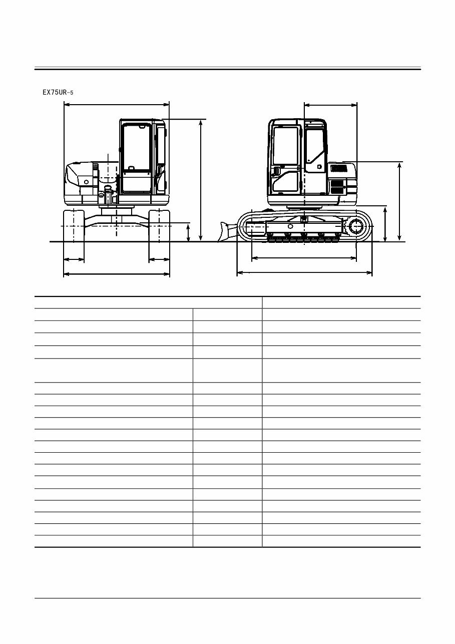
SPECIFICATIONS
M197-12-002
Model EX75UR
-5
Front-End Attachment Type − Offset Type
Bucket Capacity (Heaped) − PCSA: 0.28 m
3
(0.37 yd
3
), CECE: 0.25 m
3
Operating Weight kg (lb) 8000 (17600)
Basic Machine Weight kg (lb) 6150 (13600)
Engine
−
ISUZU A-4JG1 40.5 kW / 1900 min
-1
(55 PS / 1900 rpm)
A: Overall Width mm (ft in) 2300 (7’ 7”)
B: Cab Height mm (ft in) 2720 (8’ 11”)
C: Rear End Swing Radius mm (ft in) 1150 (3’ 9”)
D: Minimum Ground Clearance mm (ft in) 405 (1’ 4”)
E: Counterweight Clearance mm (ft in) 805 (2’ 7”)
F: Engine Cover Height mm (ft in) 1760 (5’ 9”)
G: Undercarriage Length mm (ft in) 2960 (9’ 9”)
H: Undercarriage Width mm (ft in) 2320 (7’ 7”)
I: Sprocket Center to Idler Center mm (ft in) 2290 (7’ 6”)
J: Track Shoe Width mm (ft in) 450 (1’ 6”) (Pad Crawler)
Ground Pressure kPa (kgf/cm
2
, psi) 34.5 (0.35, 5.0)
Swing Speed min
-1
(rpm) 10
Travel Speed (Fast/Slow) km/h (mph) 4.5/2.9 (2.8/1.8)
Gradeability Degree (%) 35 (70)
J J
B
D
E
F
C
I
A
H G
GENERAL / Specifications
T1-1-2
M197-12-005
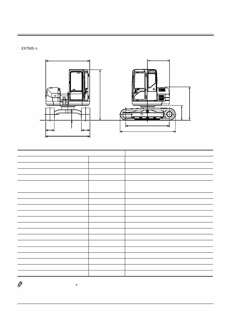
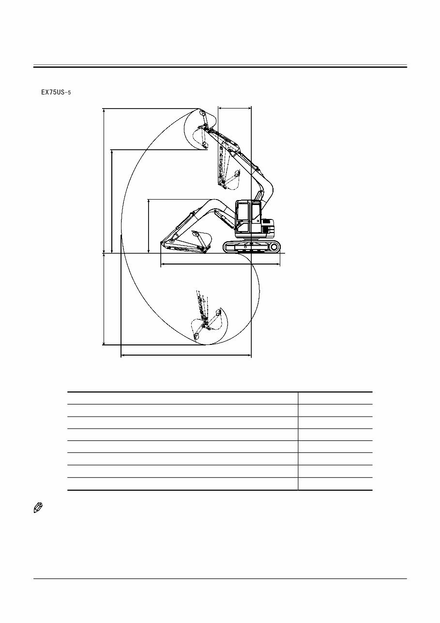
Model EX75US
-5
Front-End Attachment Type − 1.6 m Arm
Bucket Capacity (Heaped) − PCSA: 0.28 m
3
(0.37 yd
3
), CECE: 0.25 m
3
Operating Weight kg (lb) 7000 (15400)
Basic Machine Weight kg (lb) 5650 (12500)
Engine
−
ISUZU A-4JG1 40.5 kW / 1900 min
-1
(55 PS / 1900 rpm)
A: Overall Width mm (ft in) 2300 (7’ 7”)
B: Cab Height mm (ft in) 2720 (8’ 11”)
C: Rear End Swing Radius mm (ft in) 1150 (3’ 9”)
D: Minimum Ground Clearance mm (ft in)
355
∗
(1’ 2”)
E: Counterweight Clearance mm (ft in)
805
∗
(2’ 6”)
F: Engine Cover Height mm (ft in)
1730
∗
(5’ 8”)
G: Undercarriage Length mm (ft in) 2920 (9’ 7”)
H: Undercarriage Width mm (ft in) 2320 (7’ 7”)
I: Sprocket Center to Idler Center mm (ft in) 2290 (7’ 6”)
J: Track Shoe Width mm (ft in) 450 (1’ 6”) (Grouser Shoe)
Ground Pressure kPa (kgf/cm
2
, psi) 30.4 (0.31, 4.4)
Swing Speed min
-1
(rpm) 10
Travel Speed (Fast/Slow) km/h (mph) 4.5/2.9 (2.8/1.8)
Gradeability Degree (%) 35 (70)
NOTE: Dimensions marked don’t include the
shoe lug height.
J J
G
I
F
E
C
H
D
B
A
GENERAL / Specifications
T1-1-3
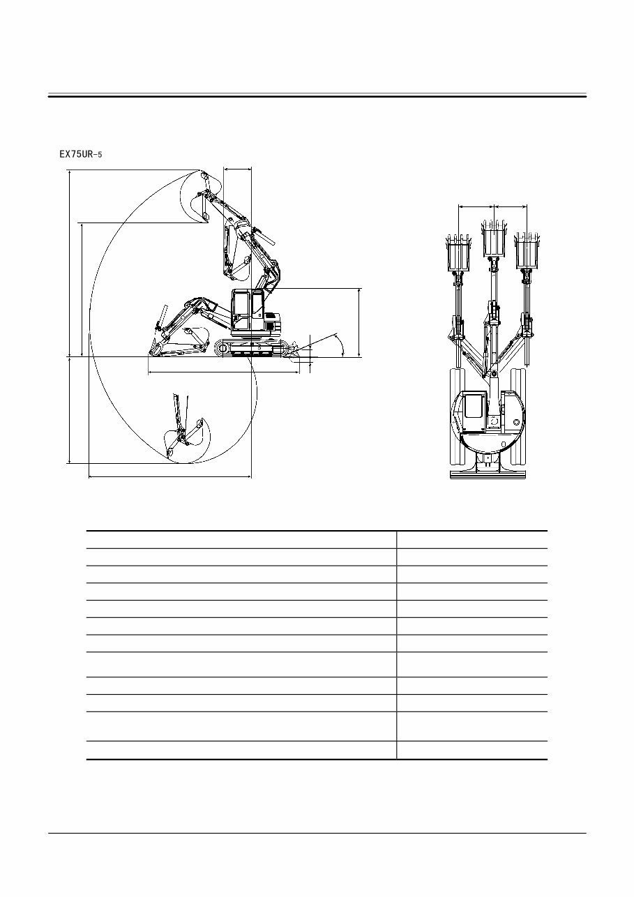
WORKING RANGES AND MACHINE
TRANSPORTATION DIMENSIONS
M197-12-003
M197-12-004
Item Category 1.75 m Arm
A: Maximum Digging Reach mm (ft in) 6430 (21’ 1”)
B: Maximum Digging Depth mm (ft in) 4230 (13’ 11”)
C: Maximum Cutting Height mm (ft in) 7420 (24’ 4”)
D: Maximum Dumping Height mm (ft in) 5320 (17’ 5”)
E: Overall Transport Height mm (ft in) 2720 (8’ 11”)
F: Overall Transport Length mm (ft in) 6040 (19’ 10”)
G: Minimum Swing Radius of Front-End Attachment
mm (ft in)
1160 (3’ 10”)
H: Blade Bottom Highest Position mm (ft in) 450 (1’ 6”)
I: Blade Bottom Lowest Position mm (ft in) 230 (9”)
J: Maximum Offset mm (ft in)
(From the front-end attachment center)
Left (Cab Side): 1100 (3’7”)
Right: 1050 (3’ 5”)
K: Maximum Approach Angle Degree 31°
D C
B
A
G
F
I
H
K
E
J J
GENERAL / Specifications
T1-1-4
M197-12-006
Item Category 1.62 m Arm
A: Maximum Digging Reach mm (ft in) 6540 (21’ 5”)
B: Maximum Digging Depth mm (ft in) 4600
∗
(15’ 1”)
C: Maximum Cutting Height mm (ft in) 7250
∗
(23’ 9”)
D: Maximum Dumping Height mm (ft in) 5170
∗
(17’ 0”)
E: Overall Transport Height mm (ft in) 2730 (8’ 11”)
F: Overall Transport Length mm (ft in) 6020 (19’ 9”)
G: Minimum Swing Radius of Front-End Attachment mm (ft in) 1670 (5’ 6”)
NOTE: Dimensions marked ∗ don’t include the
shoe lug height.
E
F
B
C
D
G
A

GENERAL / Specifications
T1-1-5
COMPONENT SPECIFICATION
Engine
MAIN SPECIFICATION
Manufacturer .................................................... ISUZU
Model No. ......................................................... 4JG1
Type ................................................................. Diesel, 4 cycle, water-cooled, in-line direct injection type
Cyl. No. – bore × stroke .................................... 4-95.4 mm×107 mm (3.76 in×4.21 in)
Piston displacement ......................................... 3059 cm
3
(187 in
3
)
Rated output ..................................................... 39 kW/1900 min
-1
(53 PS/1900 rpm)
Compression ratio ............................................ 18.6
Dry weight ........................................................ 248 kg (546 lb)
Firing order ....................................................... 1-3-4-2
Rotation direction.............................................. Clockwise (viewed from fan side)
COOLING SYSTEM
Cooling fan ....................................................... Dia. 430 mm (17 in) E type, 10 blades, draw-in type
Fan pulley speed ratio ...................................... Engine rpm×1.07
Thermostat ....................................................... Cracking temp. at atmospheric pressure: 82 °C (180 F°)
Full open tem: 95 °C (203 F°)
Water pump ...................................................... Centrifugal type, belt driven
LUBRICATION SYSTEM
Lubrication pump type ...................................... Trochoid pump
Oil filter ............................................................. Full-flow paper element type
STARTING SYSTEM
Motor ................................................................ Reduction type
Voltage ⋅ Output ................................................ 24 V ⋅ 3.2 kW
PREHEAT SYSTEM
Type ................................................................. Glow plug (24V-25sec)
ENGINE STOP SYSTEM
Type ................................................................. Fuel shut-off
ALTERNATOR
Type ................................................................. AC (with IC regulator)
Voltage ⋅ Current ............................................... 24 V ⋅ 30 A
FUEL SYSTEM
Type ................................................................. BOSCH A-type
Governor .......................................................... Centrifugal all speed control type
Injection nozzle ................................................. Multi-hole nozzle
PERFORMANCE
Lubrication oil consumption .............................. Less than 20 mL/hr (New engine, at rated output)
Fuel consumption ratio ..................................... Less than 238 g/kW/h (175 g/PS/h)
(New engine, at rated output)
Injection timing ................................................. 13 ° before T.D.C
Max. output torque ............................................ 201 N⋅ m (20.5 kgf ⋅ m, 148 lbf ⋅ ft) or more at 1600 min
-1
Injection pressure ............................................. 18.1 MPa(150 kgf/cm
2
, 2133 psi)
Compression pressure...................................... 2.94 MPa(30 kgf/cm
2
, 427 psi) @ 250 min
-1
Valve clearance (inlet/outlet) ............................. 0.4/0.4 mm (when cool)
No load speed ................................................. Min: 1000
+50
–0
min
-1
, Max.: 2090±25 min
-1
You're Reading a Preview
What's Included?
Fast Download Speeds
Online & Offline Access
Access PDF Contents & Bookmarks
Full Search Facility
Print one or all pages of your manual
$41.99
Viewed 67 Times Today


Secure transaction
What's Included?
Fast Download Speeds
Online & Offline Access
Access PDF Contents & Bookmarks
Full Search Facility
Print one or all pages of your manual
$41.99
- This is a comprehensive service and repair manual for the HITACHI ZAXIS 75US EXCAVATOR, providing essential technical information for maintenance and troubleshooting.
- The manual is designed for use by professional mechanics as well as DIY enthusiasts, offering easy-to-read text sections, high-quality diagrams, and step-by-step instructions.
- It covers every single detail of the machine, including accurate and concise text, illustrations, and manufacturer specifications.
- With this manual, anyone with basic mechanical knowledge can safely and easily service and repair their HITACHI ZAXIS 75US EXCAVATOR.
- It includes comprehensive diagrams, in-depth illustrations, and all the necessary technical information for the machine.
- It is available in a printable file format, in English language, compatible with all versions of Windows and Mac, and requires Adobe Reader and Win for access.
- The manual is suitable for immediate access without any waiting or shipping fees, allowing for instant repairs without downtime.
- It covers a wide range of topics including MOT test checks, roadside repairs, routine maintenance, engine systems, cooling, heating, air conditioning, fuel and exhaust systems, transmission, brakes, suspension, steering systems, body equipment, electrical systems, wiring diagrams, tools, general repair procedures, fault finding, and technical terms glossary.
Whether you are a professional mechanic or a DIY enthusiast, this HITACHI ZAXIS 75US EXCAVATOR FULL SERVICE REPAIR MANUAL provides all the necessary information and guidance for servicing and repairing your machine.


