INTRODUCTION IN-01 TO THE READER • This manual is written for an experienced technician to provide technical information needed to maintain and repair this machine. • Be sure to thoroughly read this manual for correct product information and service procedures. • If you have any questions or comments, at if you found any errors regarding the contents of this manual, please contact using “Service Manual Revision Request Form at the end of this man- ual. (Note: Do not tear off the form. Copy it for us- age.): Publications Marketing & Product Support Hitachi Construction Machinery Co. Ltd. TEL: 81-298-32-7173 FAX: 81-298-31-1162 ADDITIONAL REFERENCES • Please refer to the materials listed below in addition to this manual. • The Operator’s Manual • The Parts Catalog • Operation Manual of the Engine • Parts Catalog of the Engine • Hitachi Training Material MANUAL COMPOSITION • This manual consists of three portions: the Techni- cal Manual (Operational Principle), the Technical Manual (Troubleshooting) and the Workshop Man- ual. • Information included in the Technical Manual (Operational Principle): technical information needed for redeliver and delivery, operation and activation of all devices and systems. • Information included in the Technical Manual (Troubleshooting): technical information needed for operational per- formance tests, and troubleshooting procedures. • Information included in the Workshop Manual: technical information needed for maintenance and repair of the machine, tools and devices needed for maintenance and repair, maintenance standards, and removal/installation and assem- ble/disassemble procedures. PAGE NUMBER • Each page has a number, located on the center lower part of the page, and each number contains the following information: Example : T 1 -3 -5 Consecutive Page Number for Each Group Group Number Section Number T: Technical Manual W: Workshop Manual
INTRODUCTION IN-02 SAFETY ALERT SYMBOL AND HEADLINE NOTATIONS In this manual, the following safety alert symbol and signal words are used to alert the reader to the potential for personal injury of machine damage. This is the safety alert symbol. When you see this symbol, be alert to the potential for personal injury. Never fail to follow the safety instructions prescribed along with the safety alert symbol. The safety alert symbol is also used to draw attention to component/part weights. To avoid injury and damage, be sure to use appropri- ate lifting techniques and equipment when lifting heavy parts. • CAUTION: Indicated potentially hazardous situation which could, if not avoided, result in personal injury or death. • IMPORTANT: Indicates a situation which, if not conformed to the instructions, could result in damage to the machine. • NOTE: Indicates supplementary technical information or know-how. UNITS USED • SI Units (International System of Units) are used in this manual. MKS system units and English units are also indicated in parenthheses just behind SI units. Example : 24.5 MPa (250 kgf/cm 2 , 3560 psi) A table for conversion from SI units to other system units is shown below for reference purposees. Quantity To Convert From Into Multiply By Pressure MPa kgf/cm 2 10.197 MPa psi 145.0 Power kW PS 1.360 kW HP 1.341 Temperature °C °F °C×1.8+32 Velocity km/h mph 0.6214 min -1 rpm 1.0 Flow rate L/min US gpm 0.2642 mL/rev cc/rev 1.0 Quantity To Convert From Into Multiply By Length mm in 0.03937 mm ft 0.003281 L US gal 0.2642 Volume L US qt 1.057 m 3 yd 3 1.308 Weight kg lb 2.205 Force N kgf 0.10197 N lbf 0.2248 Torque N⋅m kgf⋅m 1.0197 N⋅m lbf⋅ft 0.7375
Hitachi Construction Machinery Co. Ltd Hitachi Ref. No. Attn: Publications, Marketing & Product Support Fax: 81-298-31-1162 SERVICE MANUAL REVISION REQUEST FORM NAME OF COMPANY: MODEL: PUBLECATION NO.: YOUR NAME: PAGE NO.: DATE: FAX: YOUR COMMENTS / SUGGESTIONS: Attach photo or sketch is required. If your need more space, please use another sheet. REPLY: (Copy this form for usage) (Located at the left bottom corner in the cover page) (Located at the bottom center in the page. If two or more revisions are requested, use the comment column)
1CFT-1-1 SECTION 1 GENERAL CONTENTS Group 1 Specification Specifications .......................................... T1-1-1 Working Ranges and Machine Transportation Dimensions .................... T1-1-3 Group 2 Component Layout Main Components .................................... T1-2-1 Electrical System (Overall System) .......... T1-2-2 Electrical System (Front Attachment) ....... T1-2-4 Electrical System (Monitor and Switches) .......................... T1-2-5 Electrical System (Battery) ....................... T1-2-9 Electrical System (Pressure Sensor) ........ T1-2-9 Solenoid Valve ....................................... T1-2-10 Contorl Valve .......................................... T1-2-11 Pump Device ......................................... T1-2-12 Swing Device ......................................... T1-2-12 Travel Device......................................... T1-2-12 Group 3 Component Specifications Engine ..................................................... T1-3-1 Engine Accessories ................................. T1-3-4 Hydraulic Component .............................. T1-3-5 Filter ........................................................ T1-3-7 Electrical Component ............................... T1-3-7
1CFT-1-2 (Blank)
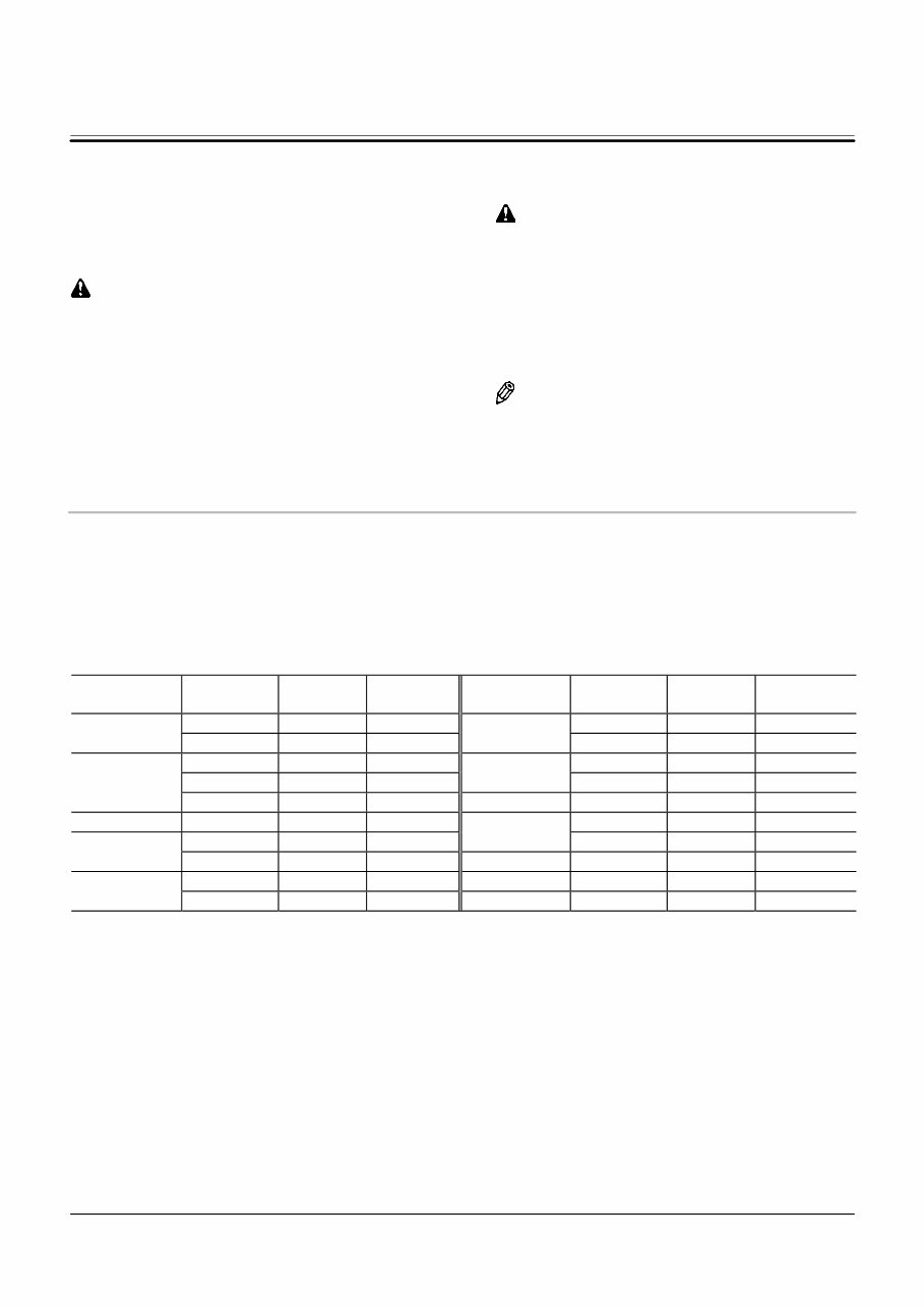
GENERAL / Specifications T1-1-1 SPECIFICATIONS ZAXIS75US-A T1CG-01-01-009 Model ZAXIS75US-A Front-End Attachment Type − 1.62 m Arm Bucket Capacity (Heaped) − PCSA: 0.28 m 3 (0.37 yd 3 ), CECE: 0.24 m 3 Operating Weight kg (lb) 7100 (15700) Basic Machine Weight kg (lb) 5890 (13000) Engine − ISUZU CC-4JG1 40.5 kW / 2100 min -1 (55 PS / 2100 rpm) A: Overall Width mm (ft in) 2320 (7 ft 7 in) B: Cab Height mm (ft in) 2690 (8 ft 10 in) C: Rear End Swing Radius mm (ft in) 1210 (4 ft 0 in) D: Minimum Ground Clearance mm (ft in) 360 ∗ (1 ft 2 in) E: Counterweight Clearance mm (ft in) 760 ∗ (2 ft 6 in) F: Engine Cover Height mm (ft in) 1740 ∗ (5 ft 9 in) G: Undercarriage Length mm (ft in) 2920 (9 ft 7 in) H: Undercarriage Width mm (ft in) 2320 (7 ft 7 in) I: Sprocket Center to Idler Center mm (ft in) 2290 (7 ft 6 in) J: Track Shoe Width mm (ft in) 450 (1’ 6”) (Grouser Shoe) Ground Pressure kPa (kgf/cm 2 , psi) 30 (0.31 ft, 4.4 in) Swing Speed min -1 (rpm) 11 Travel Speed (Fast/Slow) km/h (mph) 5.0/3.3 (8.1/5.3) Gradeability Degree (%) 35 (70) NOTE: Dimensions marked * don’t include the shoe lug height. J J B D E F C I A H G
GENERAL / Specifications T1-1-2 ZAXIS75UR T1CF-01-01-021 Model ZAXIS75UR Front-End Attachment Type − Offset Bucket Capacity (Heaped) − PCSA: 0.28 m 3 (0.37 yd 3 ), CECE: 0.24 m 3 Operating Weight kg (lb) 8200 (18100) Basic Machine Weight kg (lb) 6300 (13900) Engine − ISUZU CC-4JG1 40.5 kW / 2100 min -1 (55 PS / 2100 rpm) A: Overall Width mm (ft in) 2320 (7ft 7in) B: Cab Height mm (ft in) 2720 (8 ft 11 in) C: Rear End Swing Radius mm (ft in) 1160 (3 ft 10 in) D: Minimum Ground Clearance mm (ft in) 410 (1 ft 10 in) E: Counterweight Clearance mm (ft in) 810 (2 ft 8 in) F: Engine Cover Height mm (ft in) 1790 (5 ft 11 in) G: Undercarriage Length mm (ft in) 2960 (9 ft 9 in) H: Undercarriage Width mm (ft in) 2320 (7 ft 7 in) I: Sprocket Center to Idler Center mm (ft in) 2290 (7 ft 6 in) J: Track Shoe Width mm (ft in) 450 (1’ 6”) (Pat Crawler) Ground Pressure kPa (kgf/cm 2 , psi) 35 (0.36 ft, 5.1 in) Swing Speed min -1 (rpm) 11 Travel Speed (Fast/Slow) km/h (mph) 5.0/3.3 (8.1/5.3) Gradeability Degree (%) 35 (70) J J B D E F C I A H G
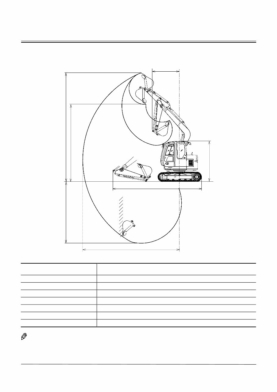
GENERAL / Specifications T1-1-3 WORKING RANGES AND MACHINE TRANSPORTATION DIMENSIONS ZAXIS75US-A T1CG-01-01-010 Category Item 1.62 m (5 ft 4 in) Arm A: Maximum Digging Reach 6430 (21 ft 1 in) B: Maximum Digging Depth 4110 (13 ft 6 in) C: Maximum Cutting Height 7210 (23 ft 8 in) D: Maximum Dumping Height 5210 (17 ft 1 in) E: Transport Height 2690 (8 ft 10 in) F: Overall Transport Length 5870 (19 ft 3 in) G: Minimum Swing Radius 1810 (5 ft 11 in) NOTE: Dimensions marked ∗ includes the shoe lug height. E F B C D G A
GENERAL / Specifications T1-1-4 ZAXIS75UR T1CF-01-01-022 T1CF-01-01-023 1.73 m Offset Front Attachment Category Item Left Offset Not Operating Offset Right Offset A: Maximum Digging Reach (mm) 5930 (19 ft 6 in) 6440 (21 ft 2 in) 5940 (19 ft 6 in) B: Maximum Digging Depth (mm) 3820 (12 ft 6 in) 4220 (13 ft 10 in) 3830 (12 ft 7 in) C: Maximum Cutting Height (mm) 6890 (22 ft 7 in) 7400 (24 ft 3 in) 6900 (22 ft 8 in) D: Maximum Dumping Height (mm) 4790 (15 ft 9 in) 5310 (17 ft 5 in) 4810 (15 ft 9 in) E: Transport Height (mm) 2720 (8 ft 11 in) F: Overall Transport Length (mm) 5470 (17 ft 11 in) 6020 (19 ft 9 in) 5480 (17 ft 12 in) G: Front Attachment Minimum Swing Radius (mm) 1080 (3 ft 7 in) 1160 (3 ft 10 in) 1080 (3 ft 7 in) H: Maximum Blade Raise Amount (mm) 450 (1 ft 6 in) I: Maximum Blade Lower Amount (mm) 230 (9.1 in) J: Offset Amount (From Front Attachment Center) (mm) Right Offset 1140 (3 ft 9 in) Left Offset 1160 (3 ft 10 in) K: Approach Angle (Deg.) 30 D C B A G F I H K E J J
Thank you for considering the Complete Workshop Service Repair Manual for the Hitachi Zaxis ZX 75US-A, 75UR Excavator.
This comprehensive manual is designed to cover every Service & Repair Procedure, providing you with the necessary guidance to save on repair costs. It includes easy-to-follow step-by-step instructions and detailed images for all servicing and repairs, making any job easy to accomplish.
Upon obtaining this manual, it becomes a valuable resource that you can refer to indefinitely. Whether you prefer a hard copy or a digital version, you have the flexibility to print out specific pages, chapters, or the entire manual. Additionally, it can be conveniently accessed on your tablet or smartphone.
MODELS COVERED:
All Models/Engines/Trim/Transmissions Types Are Covered.
CONTENTS:
This high-quality Service Repair Workshop Manual encompasses all repair procedures from A to Z, ensuring that every repair and service procedure is thoroughly addressed.
COMPUTER REQUIREMENTS:
This manual is compatible with all PC & MAC Computers, tablets, and mobile phones. The only software required is Adobe Reader, which is typically pre-installed on most computers. If not, it can be downloaded for free.
INSTANT DELIVERY:
Upon payment confirmation via Visa, MasterCard, or PayPal, the manual will be instantly emailed to the address provided during checkout.