INTRODUCTION IN-01 TO THE READER • This manual is written for an experienced technician to provide technical information needed to maintain and repair this machine. • Be sure to thoroughly read this manual for cor- rect product information and service procedures. • If you have any questions or comments, at if you found any errors regarding the contents of this manual, please contact using “Service Manual Revision Request Form” at the end of this man- ual. (Note: Do not tear off the form. Copy it for us- age.): Publications Marketing & Product Support Hitachi Construction Machinery Co. Ltd. TEL: 81-298-32-7173 FAX: 81-298-31-1162 ADDITIONAL REFERENCES • Please refer to the materials listed below in addition to this manual. • The Operator’s Manual • The Parts Catalog • Operation Manual of the Engine • Parts Catalog of the Engine • Hitachi Training Material MANUAL COMPOSITION • This manual consists of three portions: the Techni- cal Manual (Operational Principle), the Technical Manual (Troubleshooting) and the Workshop Man- ual. • Information included in the Technical Manual (Operational Principle): technical information needed for redelivery and delivery, operation and activation of all devices and systems. • Information included in the Technical Manual (Troubleshooting): technical information needed for operational per- formance tests, and troubleshooting procedures. • Information included in the Workshop Manual: technical information needed for maintenance and repair of the machine, tools and devices needed for maintenance and repair, maintenance standards, and removal/installation and assem- ble/disassemble procedures. PAGE NUMBER • Each page has a number, located on the center lower part of the page, and each number contains the following information: Example : T 1 -3 -5 Consecutive Page Number for Each Group Group Number Section Number T: Technical Manual W: Workshop Manual
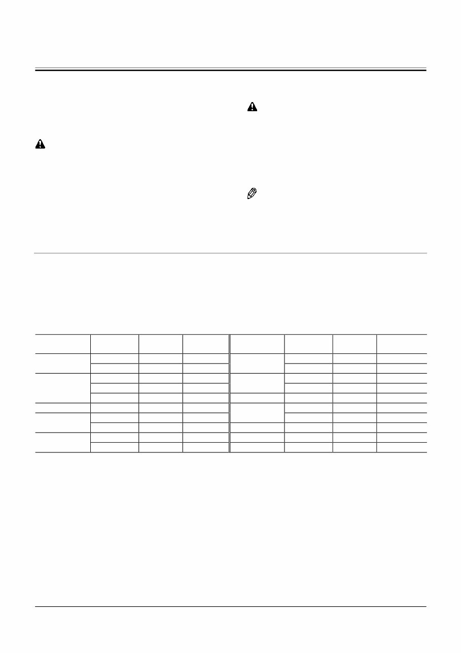
INTRODUCTION IN-02 SAFETY ALERT SYMBOL AND HEADLINE NOTATIONS In this manual, the following safety alert symbol and signal words are used to alert the reader to the potential for personal injury of machine damage. This is the safety alert symbol. When you see this symbol, be alert to the potential for personal injury. Never fail to follow the safety instructions prescribed along with the safety alert symbol. The safety alert symbol is also used to draw attention to component/part weights. To avoid injury and damage, be sure to use appropri- ate lifting techniques and equipment when lifting heavy parts. • CAUTION: Indicated potentially hazardous situation which could, if not avoided, result in personal injury or death. • IMPORTANT: Indicates a situation which, if not conformed to the instructions, could result in damage to the machine. • NOTE: Indicates supplementary technical information or know-how. UNITS USED • SI Units (International System of Units) are used in this manual. MKSA system units and English units are also indicated in parenthheses just behind SI units. Example : 24.5 MPa (250 kgf/cm 2 , 3560 psi) A table for conversion from SI units to other system units is shown below for reference purposees. Quantity To Convert From Into Multiply By MPa kgf/cm 2 10.197 Pressure MPa psi 145.0 kW PS 1.360 Power kW HP 1.341 Temperature °C °F °C×1.8+32 km/h mph 0.6214 Velocity min -1 rpm 1.0 Flow rate L/min US gpm 0.2642 mL/rev cc/rev 1.0 Quantity To Convert From Into Multiply By mm in 0.03937 Length mm ft 0.003281 L US gal 0.2642 L US qt 1.057 Volume m 3 yd 3 1.308 Weight kg lb 2.205 N kgf 0.10197 Force N lbf 0.2248 N⋅m kgf⋅m 1.0197 Torque N⋅m lbf⋅ft 0.7375
191T-1-1 SECTION 1 GENERAL ―CONTENTS― Group 1 Specification Specifications ............................................ T1-1-1 Working Ranges and Machine Dimensions for Transportation ................ T1-1-2 Component Specifications ........................ T1-1-3 Group 2 Component Layout Main Components ..................................... T1-2-1 Electrical System (Component Layout) ............................... T1-2-2 Electrical System (Relays) ........................ T1-2-3 Electrical System (Monitor and Switch) ............................... T1-2-4 Others ....................................................... T1-2-6
191T-1-2 (Blank)
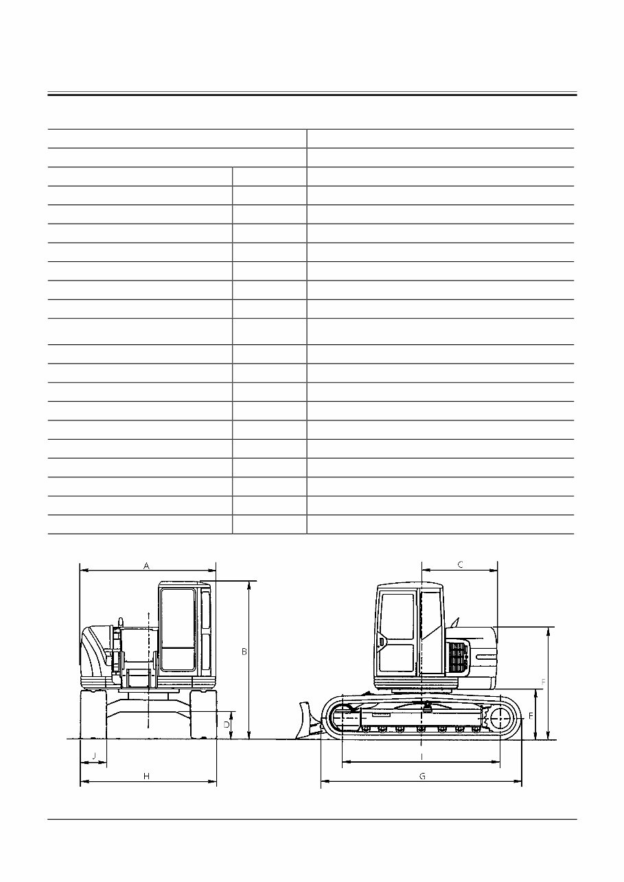
GENERAL / Specifications T1-1-1 SPECIFICATIONS Machine Model EX135UR Machine Type Cab Mounted Type of Front End Attachment − Offset Type Standard Bucket Capacity (Heaped) m 3 (yd 3 ) 0.45 (0.59): PCSA, 0.40: CECE Operating Weight kg (lb) 14000 (31000) Basic Machine Weight kg (lb) 10900 (24000) Engine − ISUZU 4BG1T, 63 kW/1900 min -1 (85 PS/1900 rpm) A: Overall Width mm (ft in) 2490 (8’ 2”) B: Cab Height mm (ft in) 2800 (9’ 2”) C: Swing Radius mm (ft in) 1370 (4’ 6”) D: Ground Clearance of Undercarriage mm (ft in) 430 (1’ 5”) E: Clearance Height Under Upper mm (ft in) 890 (2’ 11”) F: Height of House mm (ft in) 1980 (6’ 6”) G: Track Length mm (ft in) 3620 (11’ 11”) H: Undercarriage Overall Width mm (ft in) 2490 (8’ 2”) l : Crawler Base mm (ft in) 2900 (9’ 6”) J: Track Shoe Width mm (ft in) 500 (1’ 8”) Ground Pressure kPa (kgf/cm 2 ) 47 (0.48) Maximum Swing Speed min -1 (rpm) 13.4 (13.4) Maximum Travel Speed (Fast/Slow) km/h (mph) 5.0 (3.2)/3.5(2.2) Gradability Degree (%) 35 (70) M191-11-001 Base Machine Dimension Diagram
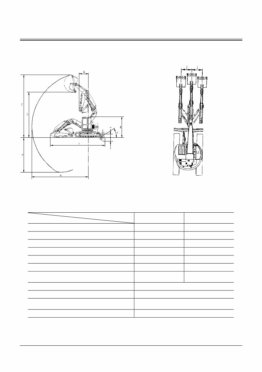
GENERAL / Specifications T1-1-2 WORKING RANGES AND MACHINE DIMENSIONS FOR TRANSPORTATION M191-11-002 M191-11-004 Working Dimension Arm Size Description 2.21 m 2.51 m A: Maximum Reach mm (ft in) 7540 (24’ 9”) 7830 (25’ 8”) B: Maximum Digging Depth mm (ft in) 4800 (15’ 9”) 5100 (16’ 9”) C: Maximum Height of Cutting Edge mm (ft in) 8550 (28’ 1”) 8790 (28’ 10”) D: Maximum Dumping Height mm (ft in) 6140 (20’ 2”) 6380 (20’ 11”) E: Shipping Height mm (ft in) 2800 (9’ 2”) 2800 (9’ 2”) F: Shipping Length mm (ft in) 7390 (24’ 3”) 7450 (24’ 5”) G: Minimum Radius of Equipment and Attachment mm (ft in) 1240 (4’ 1”) 1470 (4’ 10”) H: Blade Maximum Lifting mm (ft in) 490 (1’ 7”) I : Blade Maximum Lowering mm (ft in) 500 (1’ 8”) J : Offset Right mm (ft in) Offset Left mm (ft in) 1160 (3’ 7”) 1100 (3’ 9”) K: Blade Approach Angle (degree) 30
This Hitachi EX135UR Excavator Service Manual Set consists of three portions: the Technical Manual (Operation Principle), the Technical Manual (Troubleshooting), and the Workshop Manual.
Information Included in the Technical Manual (Operation Principle): Technical information needed for redelivery and delivery, operation, and activation of all devices and systems.
Information Included in the Technical Manual (Troubleshooting): Technical information needed for operational performance tests and troubleshooting procedures.
Information Included in the Workshop Manual: Technical information needed for maintenance and repair of the machine, tools and devices needed for maintenance and repair, maintenance standards, and removal/installation and assemble/disassemble procedures.
The Workshop Manual contents include:
Introduction
Safety
General Information
Upperstructure
Undercarriage
Front Attachment
Engine and Accessory
The Troubleshooting Manual contents include:
Introduction
Safety
Operation Performance Test
Troubleshooting
The Operation Principle Manual contents include:
Introduction
General
System
Component Operation
The Service Manual (Manual #KM191E) consists of the following three separate volumes:
File Format: .PDF
Total pages: 949
Size: 21Mb
Manual Language: English
This manual contains information and data specific to this model, including specs, diagrams, actual real photo illustrations, and schemes. It is invaluable for diagnosing, repairing, and maintaining Hitachi machinery. Additionally, the digital format allows for space savings and the convenience of using the Search feature in Acrobat to find specific information and print out exact pages as needed.
If you have any questions or are searching for a specific manual, feel free to reach out. Have a nice day!