



H55DR
H55DR
Service Manual


INTRODUCTION
To insure a long life for the machine and the engine and to prevent failure and problems,
proper operation, maintenance and repairs are imperative.
This service manual includes an “outline,” “structure and operation,” “inspection and
adjustment,” “disassembly and assembly,” “standard maintenance,” and “repair and re-
placement of parts” of the machine which are necessary to carry out the inspections and
repairs in the repair shop.
We trust that this manual will help you to effectively carry out the necessary. Repairs
should they arise, also provide a accurate description of the product, and the correct re-
pair procedures.


CONTENTS
1. Precautions on Maintenance
2. Outline
3. Attachment
4. Engine
5. Main Pump
6. Hydraulic Oil Filter
7. Control Valve
8. Joystick
(Pilot Valve)
9. Pilot Valve (1)
(Travel)
10. Pilot valve (2)
(Dozer)
11. Solenoid Valve
(Swing • P.T.O.)
12. Slew Motor
13. Travel Motor
14. Hydraulic Cylinder
15. Swivel Joint
16. Crawler
17. Spring Case and Grease Cylinder
18. Idler
19. Sprocket
20. Track Roller
21. Carrier Roller
22. Electrical Equipment
23. Cooler

1 PRECAUTIONS ON MAINTENANCE
1. Correct operation
Correct operation means to follow the correct “procedure” and “method.”
Procedure focuses on speed and accuracy of each job.
In the method, are addressed what type of facility, tools, instruments, materials, oil
should be used, how and which part should be checked, adjusted or disassembled,
and what matters to attend to.
2. Precautions on operation
1. Safety check
Check that stoppers and sleepers are correctly installed for the vehicle jack-up op-
eration.
2. Preparation
Prepare all of the tools and inspect and adjust the instruments.
3. For efficiency
1) Understand the state before disassembly.
What is the problem? Is disassembly absolutely necessary?
2) Before disassembly
Determine whether match marks are necessary. For the electrical system, dis-
connect the cable from the battery terminal.
3) Precautions for disassembly
In stead of checking all of the disassembled parts at once, check each part in-
dividually as it is disassembled. When removing the hydraulic unit or the hoses,
mount a dust cap on the connection.
4) Repair of disassembled parts
Keep the disassembled parts in order. Clearly distinguish the parts to be re-
placed with new parts from those to be reused. Packings, seals, rings, split pins
must be replaced.
NOTE:
Electrical equipment, rubbers and V belts (which are easily affected by water
and oil) must be handled carefully in order to prevent soiling them.
5) Clean disassembled parts
Thoroughly clean the disassembled parts.
6) Assembly
Perform the assembly correctly (tightening torque, application of Three Bond,
screw lock, grease, use of seal tape, etc.). Also install the hose correctly.
1-1
Hose mark Hose mark

2 OUTLINE
CONTENTS
2-1 Location of serial No.
2-2 Name of each part
2-3 Dimensions and specification
2-4 Weight list
2-5 Oil and grease supply points
2-6 List of supply oil and grease
2-7 When to repair
2-8 Hydraulic circuit diagram
MACHINE
MASCHINE
MACCHINA
MAKUIME
MASKIN
MODEL
MODELL/MODELLE
MODELLO/MODELOS
MODEL
MODELL/MODELLE
MODELLO/MODELOS
NO.
WEIGHT/GEWICHT
GEWICHT/POID
PESO/PESO/VEKT
YEAR/JAAR
BAUJAHR/ANNEE
ANNO/ANO/ÅR
NO.
POWER/VERMOGEN
LEISTUNG/PUISSANCE
POTENSA/POTENCEA
YTELSE
ENGINE
MOTOR
MOTEUR
MOTORE
MODOR
Unit B Windmill Lane, Denton, Manchester M34 3SP, United Kingdom
MADE IN JAPAN
MAX. DRAWBAR
PULL
MAX. VERT.
LOAD
kg
kN
kN
kW/ min
-1
2-1
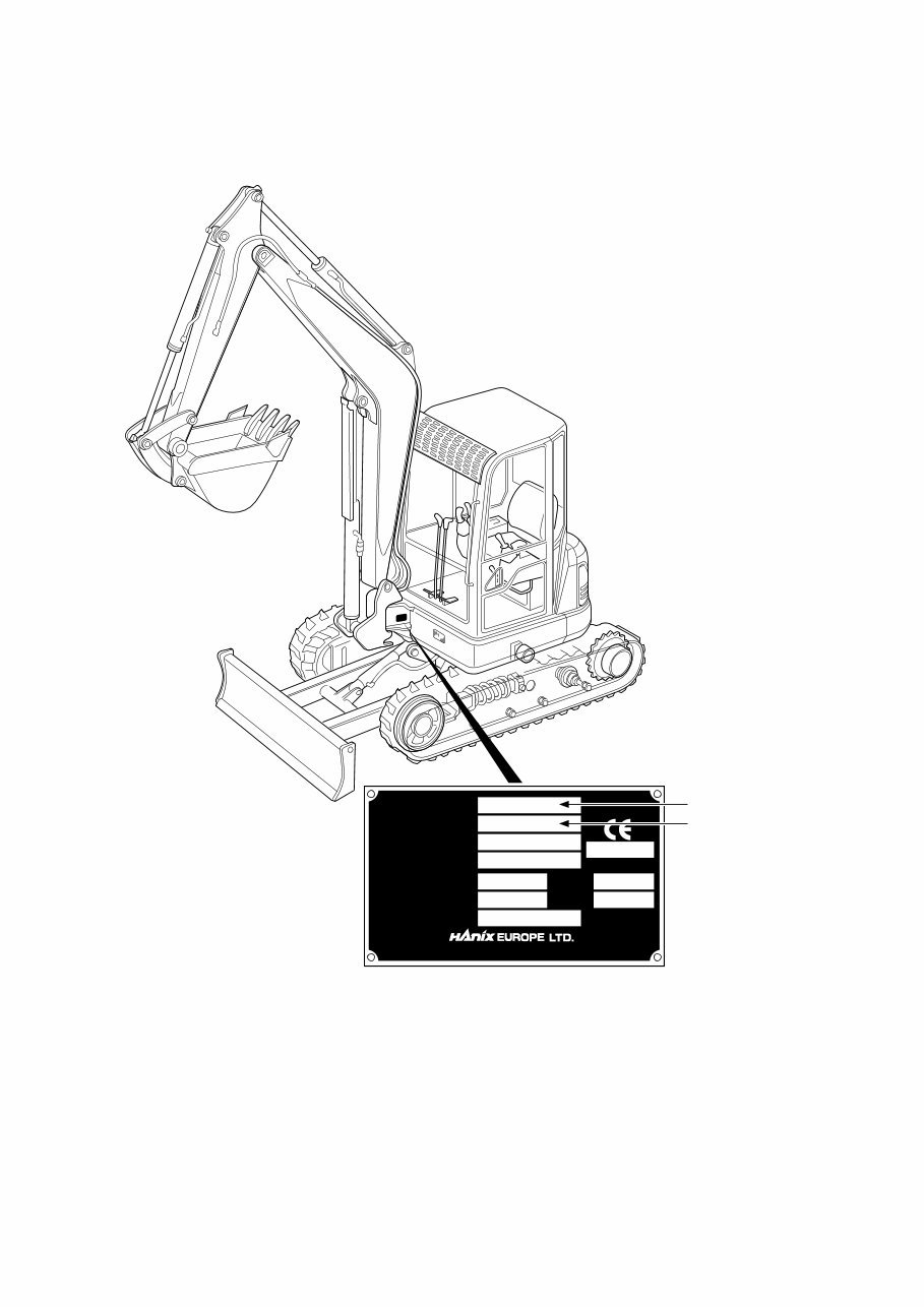
2-1 Location of Serial Number
Model Name.
Serial No.
2-2
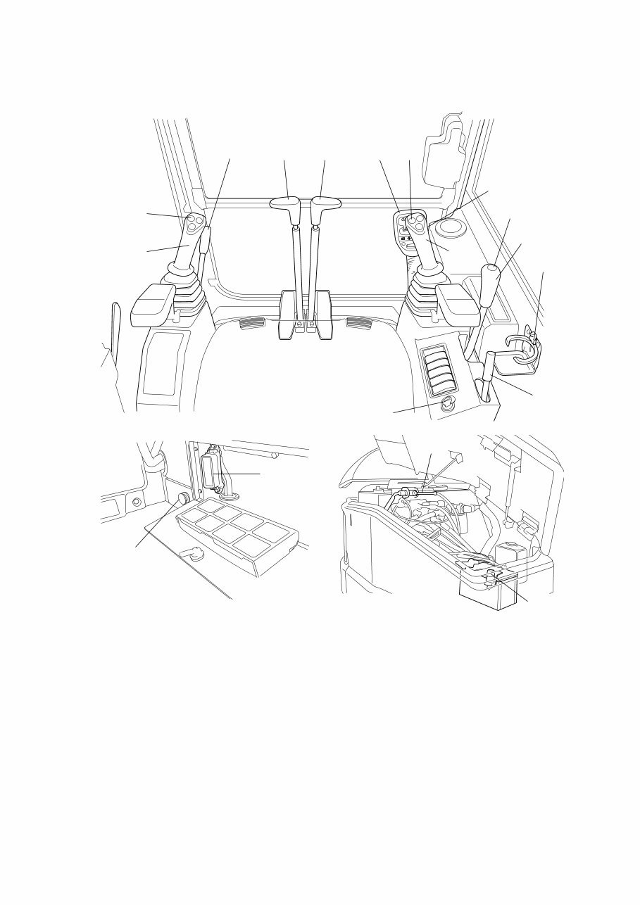
2-2 Name of each part
1. Meter panel 2. Starter switch
3. Horn switch 4. Fuse box
5. Right operation lever 6. Left operation lever
7. Accelerator lever 8. Dozer lever
9. Right travelling lever 10. Left travelling lever
11. Swing operation switch 12. P.T.O. operation switch
13. Safety lock lever 14. Over drive switch
15. Manual boom lowering lever 16. Power supply
17. Cup holder 18. Isolation switch
E
F
C
H
6
10 9
5
8
17
7
2
13
4
16
15
18
1 12
3
11
14
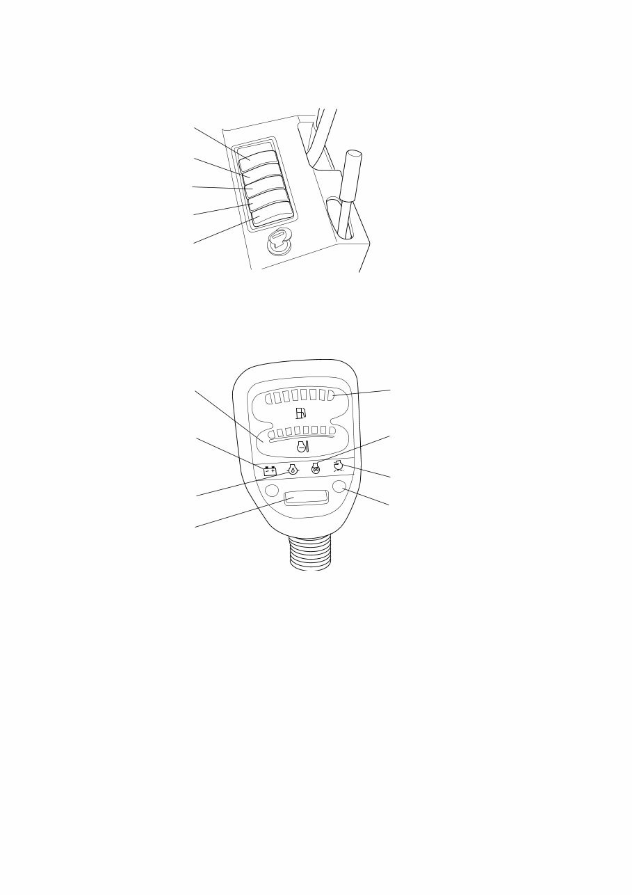
19. Working lamp switch 20. Heater switch
21. Fan switch 22. Wiper and washer switch
23. Automatic decelerator switch (Optional equipment)
1. Fuel gauge lamp 2. Water temperature gauge lamp
3. Charge lamp 4. Engine oil pressure lamp
5. Glow lamp 6. Air filter lamp
7. Over drive lamp 8. Hour meter
E
F
C
H
22
21
20
19
2
3
4
1
5
6
7
8
23
2-3
You're Reading a Preview
What's Included?
 Lifetime Access
Fast Download Speeds
Online & Offline Access
Access PDF Contents & Bookmarks
Full Search Facility
Print one or all pages of your manual
$36.99
Hanix H55DR mini excavator service and parts manual
Viewed 11 Times Today

What's Included?
Lifetime Access
Fast Download Speeds
Online & Offline Access
Access PDF Contents & Bookmarks
Full Search Facility
Print one or all pages of your manual
$36.99

Secure transaction
What's Included?
Lifetime Access
Fast Download Speeds
Online & Offline Access
Access PDF Contents & Bookmarks
Full Search Facility
Print one or all pages of your manual
Description
Official service and parts manual for the Hanix H55DR mini excavator. This manual is a valuable resource for professional mechanics and DIY enthusiasts alike.
- Bookmarked chapters for easy navigation, allowing quick access to specific repair service procedures.
- Notes, cautions, and warnings throughout each chapter provide critical service information.
- Numbered instructions guide you through every repair procedure in a step-by-step fashion.
- Bold figured numbers help you quickly match illustrations with instructions.
- Detailed illustrations, exploded diagrams, drawings, and photos guide you through every service repair procedure.
- Numbered table of contents for easy and fast information retrieval.
Manual Language: English
File Format: .PDF
File Delivery: Instant
Pages: 293
To purchase this repair manual, simply click on the green "instant" button at the upper left-hand corner of this page. After purchasing, download it to your computer to save and print pages whenever needed.


