

Gehl 803 parts manual. s/n AC02528 and up
What's Included?
Fast Download Speeds
Online & Offline Access
Access PDF Contents & Bookmarks
Full Search Facility
Print one or all pages of your manual

Compact Excavator
Beginning Serial Number: AC02528
803
Form No.
918076
Revision C
May 2008
Parts Manual
© 2008 Gehl Company • All Rights Reserved. • Printed in USA
®

INTRODUCTION
When ordering service parts, specify the correct
part number, full description, quantity required, the
unit model number and serial number. For your
safety and continued proper operation, use only
genuine GEHL service parts.
The model and serial number for this unit are on a
tag located on a panel on the front of the cabin.
''Right'' and ''left'' are determined from a position
sitting on the seat and facing forward.
GEHL Company reserves the right to make
changes or improvements in the design or
construction of any part of the unit without
incurring the obligation to install such changes
on any previously delivered units.
Refer to the abbreviations table located on this
page for the various fastener descriptions.
Standard attaching hardware torque values are also
provided on the inside back cover. Metric torque
values shown in the illustrations are in Newton-
meters and can be converted to foot-pounds by
multiplying by 0.738.
Specific Reference Numbers, indicating a
complete assembly, are circled in some illustra-
tions. A small bag, pictured in some illustrations,
indicates a seal kit (seals, o-rings, etc.). In the
exploded view parts list, additional information
may follow the Reference Number.
Serial number breaks are indicated as follows:
• (SN 999 and before) - indicates serial numbers
up to and including 999.
• (SN 1000 - 2000) - indicates serial numbers
between 1000 and 2000.
• (SN 999 and up) - indicates serial numbers
including 999 and after.
Serial number exceptions and inclusions are
indicated as follows:
• (SN 999 and before except 997) - indicates
serial numbers up to and including 999,
EXCEPT 997.
• (SN 1000 - 2000 except 1996 including 997) -
indicates serial numbers between 1000 and
2000, INCLUDING 997 EXCEPT 1996.
• (SN 2001 and up including 1996) - indicates
serial numbers including 2001 and after,
INCLUDING 1996.
Unless otherwise specified, all cap screws, nuts,
and bolts are Grade 8.8, cadmium or zinc plated.
NOTE: The following abbreviations may be
used herein:
ASSD...................... Assembled
ASSY...................... Assembly
AR .......................... As Required
CB........................... Carriage Bolt
CP ........................... Cotter Pin
CS ........................... Cap Screw (Hexagon Head)
CYL ........................ Cylinder
DIA......................... Diameter
FHCS ...................... Flat Head Cap Screw
GR .......................... Grade
HB .......................... Hex Bolt
HLN........................ Hex Lock Nut
HN .......................... Hex Nut
HP ........................... High Pressure
HYD ....................... Hydraulic
INS ......................... Insert
LN........................... Lock Nut
LT ........................... Left
LW .......................... Lock Washer
M ............................ Meter or Meters
MM/mm ................. Millimeter
NPT......................... National Pipe Thread
RH .......................... Right Hand
RT ........................... Right
SHCS ...................... Socket Head Cap Screw
SLTD ...................... Slotted
SN........................... Serial Number or Slotted Nut
SQ........................... Square
W/ ........................... With
W/O ........................ Without

Printed in U.S.A 1 918076/CP0508
TABLE OF CONTENTS
Introduction ..................... Inside Front Cover
Table of Contents .........................................1
Decal Locations ...........................................4
Diesel Engine - Tier III ................................8
Diesel Engine - Tier II .................................9
Engine Mounts - Tier III ............................10
Engine Mounts - Tier II .............................11
Cylinder Head, Valve Cover ......................12
Cylinder Block ...........................................13
Seal - Crankshaft - Tier III .........................14
Seal - Crankshaft - Tier II ..........................15
Oil Pan - Tier III ........................................16
Oil Pan - Tier II ..........................................17
Camshaft - Tier III .....................................18
Camshaft - Tier II ......................................19
Crankshaft, Piston - Tier III .......................20
Crankshaft, Piston - Tier II ........................21
Lubrication - Tier III ..................................22
Lubrication - Tier II ...................................23
Cooling System - Tier III ...........................24
Cooling System - Tier II ............................25
Fuel Injection System - Tier III .................26
Fuel Injection System - Tier II ...................27
Engine Air Filter - Tier III .........................28
Engine Air Filter - Tier II ..........................29
Intake Manifold - Tier III...........................30
Intake Manifold - Tier II ............................31
Exhaust Components - Tier III ..................32
Exhaust Components - Tier II ....................33
Diesel Tank ................................................34
Hydraulic Pump Drive ...............................35
Fuel Supply - Tier III .................................36
Fuel Supply - Tier II ..................................37
Auto Idle/Throttle - Tier III .......................38
Throttle Lever - Tier II...............................39
Radiator - Tier III .......................................40
Radiator - Tier II ........................................41
Turntable Drive Unit Installation ...............44
Turntable Drive Unit ..................................46
Oil Cooler ..................................................47
Pilot Control Drive Unit ............................48
Drive Motor Installation ............................50
Drive Motor (Mag 50) ...............................52
Drive Motor (Mag 44) ...............................53
Hydraulic Oil Tank ....................................55
Hydraulic Pump ......................................... 58
Hydraulic Pump Components .................... 59
Control Valve Fittings ............................... 60
Control Valve Assembly............................ 62
Pilot Oil Supply Unit ................................. 63
Cut-Off Valve ............................................ 64
Swivel Joint................................................67
Joysticks ..................................................... 68
Pilot Valve, Travel ..................................... 70
Auxiliary Hydraulics - Pilot Valve ............ 72
Control Valve Fittings ............................... 72
Dozer Blade Valve ..................................... 73
Proportional Valve (Option) ...................... 74
Selection Valve .......................................... 75
ISO/SAE Valve .......................................... 76
Manifold Block .......................................... 77
Valve Block ...............................................78
Manifold..................................................... 80
Hydraulic Pump Installation ...................... 82
Boom Installation....................................... 83
Boom Cylinder ........................................... 84
Dipper Arm Installation ............................. 86
Dipper Arm Cylinder ................................. 87
Bucket Installation - Short Dipper Arm..... 88
Bucket Installation - Long Dipper Arm
(Option) .................................................. 89
Bucket Cylinder ......................................... 90
Boom Offset Cylinder Installation ............. 92
Boom Offset Cylinder ................................ 93
Dozer Blade Installation ............................ 94
Dozer Blade Cylinder ................................ 95
Auxiliary Hydraulics Installation............... 96
Proportional Control (Option) ................... 98
ISO/SAE Valve Installation ....................... 99
Hydraulic Tank Hoses ............................. 100
Pilot Pressure Hoses................................. 102
Battery...................................................... 103
Dashboard ................................................ 104
Radio (Option) ......................................... 106
Horn ......................................................... 107
Relay Box ................................................ 108
Cab Work Lights - Front (Option) ........... 110
Cab Work Light - Rear (Option).............. 112
Boom Work Light .................................... 113
Wire Harness - Engine ............................. 114

918076/CP0508 2 Printed in U.S.A
TABLE OF CONTENTS
Wire Harness - Chassis, Engine ...............115
Wire Harness - Chassis ............................117
Wire Harness - Oil Control ......................118
Wire Harness - Armrest ...........................119
Wire Harness - Switch .............................120
Wire Harness - Work Light - Front..........122
Wire Harness - Cab ..................................123
Wire Harness - Auto-Idle (Option) ..........124
Wire Harness - Proportional Control
(Option) ................................................126
Dozer Blade .............................................127
Undercarriage, Rubber Track...................128
Rubber Track ...........................................129
Undercarriage, Steel Track (Option)........130
Steel Track (Option) ................................131
Track Tensioner, Rubber Track ...............132
Track Tensioner, Steel Track (Option) ....134
Track Roller (Rubber Track) ...................136
Bottom Roller ..........................................137
Top Roller ................................................138
Top Roller ................................................139
Chassis .....................................................140
Lubrication ...............................................141
Counterweight ..........................................142
Counterweight (Option) ...........................144
Engine Hood - Tier III .............................145
Engine Hood - Tier II...............................146
Tank Cover ..............................................148
Partition Wall ...........................................149
Isolation Mats ..........................................152
Undercarriage Cover ................................155
Chassis Cover ..........................................156
Mirrors .....................................................158
Boom........................................................159
Dipper Arm - Short ..................................160
Dipper Arm - Long (Option) ...................162
Cab Mounting ..........................................164
Cab Frame 1 .............................................165
Cab Frame 2 .............................................168
Cab Door ..................................................171
Windshield ...............................................172
Cabin Windows........................................175
Cab Trim ..................................................176
Operator’s Seat ........................................178
Heater .......................................................180
Air Conditioning (Option) .......................182
Air Conditioning Compressor (Option) ...183
Air Conditioning Installation (Option) ....185
Rotating Beacon (Option) ........................188
Tools ........................................................189
Alphabetical Index ...................................191
Numerical Index ......................................193

Printed in U.S.A 3 918076/CP0508
NOTES

918076/CP0508 4 Printed in U.S.A
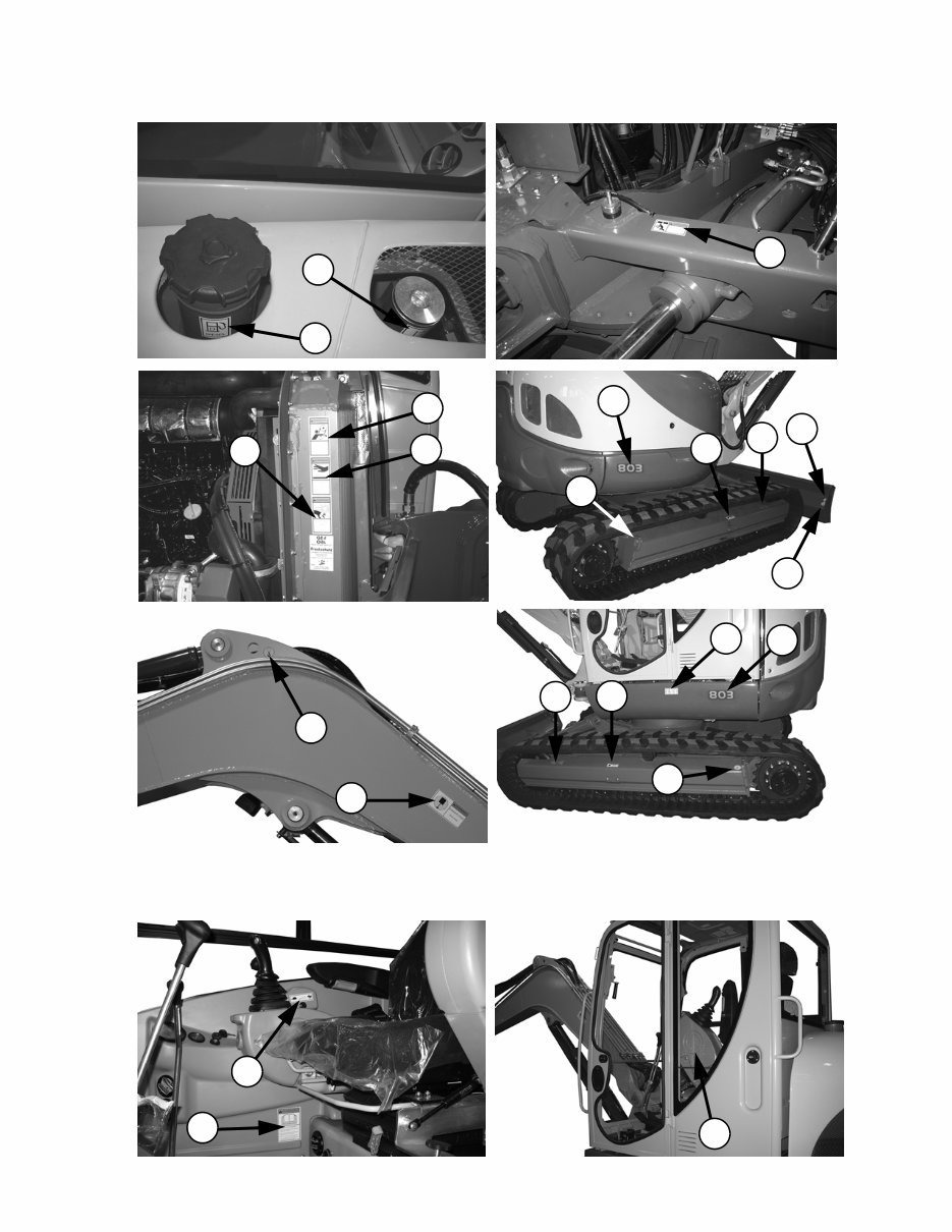
DECAL LOCATIONS
GENERAL INFORMATION
Decal location information is provided to assist in
the proper selection and application of new decals,
in the event the original decals become damaged or
the machine is repainted. Refer to the listing for the
illustration reference number, part number,
description and quantity of each decal provided in
the kit. Refer to the appropriate illustrations for
replacement locations.
To ensure proper selection of the correct replace-
ment decals, compare all of the various closeup
location drawings to your machine before starting
to refinish the unit. Then circle each decal shown
(applicable to your machine) while checking off its
part number in the listing. After you have verified
all the decals needed for replacement, place any
extra unnecessary decals aside for disposal.
NOTE: Refer to the SAFETY chapter of the
Operator's Manual for the specific information
provided on all of the various safety decals
furnished in the decal kit(s).
NEW DECAL APPLICATION
If there is a decal on a part that is to be replaced,
be sure that the decal is applied to the replacement
part. Surfaces MUST be free from dirt, dust, grease
and other foreign material before applying the new
decal. To apply, remove the smaller portion of the
decal backing paper and apply this part of the
exposed adhesive backing to the clean surface
while maintaining proper position and alignment.
Peel the other portion of the backing paper off
slowly while applying hand pressure to smooth out
the decal surface.
CAUTION
ALWAYS follow safety precautions on decals.
Replace the decals if they are damaged, or if
the unit is repainted. If repainting, BE SURE all
applicable decals are affixed to the machine.
The decal kit for the 803 Compact Excavator is
listed below:
PAINT NOTICE
Use this list to order paint for refinishing:
167788 4 qts. Construction Yellow (GEHL)
167780 4 qts. Light Gray (GEHL)
167774 4 qts. Dark Gray (GEHL)
167789 6 (12.8 oz. Spray Cans) Yellow (GEHL)
167775 6 (12.8 oz. Spray Cans) Dark Gray (GEHL)
167781 6 (12.8 oz. Spray Cans) Light Gray (GEHL)
Ref.
No.
Part
No. Decal/Part Description Qty.
176918 Decal Kit - 803 1
1 161965 Decal/Diesel Fuel 1
2 161966 Decal/Hydraulic Oil 1
3 161970 Decal/Arrow 2
4 161981 Decal/Lift Point 4
5 161982 Decal/Tiedown Point 4
6 161985 Decal/Warning Keep Away 2
7 161986 Decal/Warning Read Manual 1
8 161987 Decal/Warning Rotating Fan 2
9 162450 Decal/Travel Left 1
10 162451 Decal/Travel Right 1
11 163973 Decal/Warning Mandatory Shutdown 1
12 163974 Decal/Throttle Speed 1
13 163975 Decal/Warning Avoid Injury 2
14 163976 Decal/Warning Avoid Injury 1
15 163977 Decal/Warning Entanglement Hazard 1
16 163978 Decal/Warning Hot Surface 1
17 164854 Decal/Warning Avoid Injury 1
19 173907 Decal/803 2
20 177442 Decal SAE/ISO Control 1
21 177871 Decal/Dozer Blade Up/Down 1
22 177441 Decal/Warning Avoid Injury 1
23 177443 Decal/Controls SAE/ISO Lt 1
24 177444 Decal/Controls SAE/ISO Rt 1
25 205842 Lube Chart 1
26 184043 Decal/Gehl 3.75 x 15.92 (white) 1
27 183935 Decal/Gehl 5.50 x 23.34 1
28 184069 Decal/Gehl 6.75 x 28.65 2
29 205088 Decal/Lift Capacity 1
Printed in U.S.A 5 918076/CP0508
DECAL LOCATIONS
20
13 3
5
19
4
6
15
16 8
13
4
5
5
19
3
22
1
2
7
12
25
Both Sides (items 4 and 6) Both Sides (except item 20)
918076/CP0508 6 Printed in U.S.A
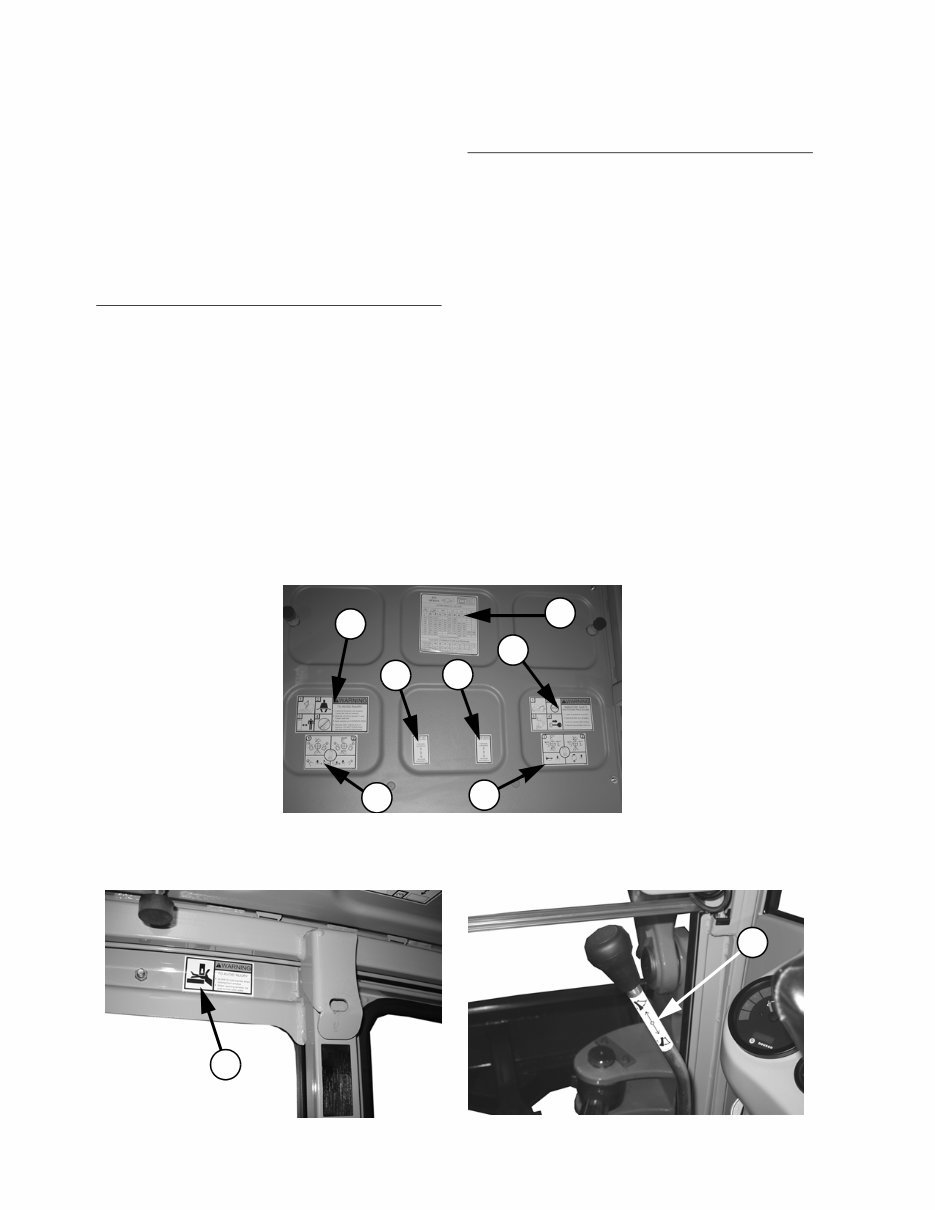
DECAL LOCATIONS
17
21
29
14
23
9 10
11
24
Overhead Decals - positioning may vary
NOTE: The following is a duplicate listing of
the decals from page 4. It is provided for
convenience when selecting decals from the
appropriate illustrations.
The decal kit for the 803 Compact Excavator is
listed below
Ref.
No.
Part
No. Decal/Part Description Qty.
176918 Decal Kit - 803 1
1 161965 Decal/Diesel Fuel 1
2 161966 Decal/Hydraulic Oil 1
3 161970 Decal/Arrow 2
4 161981 Decal/Lift Point 4
5 161982 Decal/Tiedown Point 4
6 161985 Decal/Warning Keep Away 2
7 161986 Decal/Warning Read Manual 1
8 161987 Decal/Warning Rotating Fan 2
9 162450 Decal/Travel Left 1
10 162451 Decal/Travel Right 1
11 163973 Decal/Warning Mandatory Shutdown 1
12 163974 Decal/Throttle Speed 1
13 163975 Decal/Warning Avoid Injury 2
14 163976 Decal/Warning Avoid Injury 1
15 163977 Decal/Warning Entanglement Hazard 1
16 163978 Decal/Warning Hot Surface 1
17 164854 Decal/Warning Avoid Injury 1
19 173907 Decal/803 2
20 177442 Decal SAE/ISO Control 1
21 177871 Decal/Dozer Blade Up/Down 1
22 177441 Decal/Warning Avoid Injury 1
23 177443 Decal/Controls SAE/ISO Lt 1
24 177444 Decal/Controls SAE/ISO Rt 1
25 205842 Lube Chart 1
26 184043 Decal/Gehl 3.75 x 15.92 (white) 1
27 183935 Decal/Gehl 5.50 x 23.34 1
28 184069 Decal/Gehl 6.75 x 28.65 2
29 205088 Decal/Lift Capacity 1
Ref.
No.
Part
No. Decal/Part Description Qty.

Printed in U.S.A 7 918076/CP0508
DECAL LOCATIONS
28
28
27
26
918076/CP0508 8 Printed in U.S.A
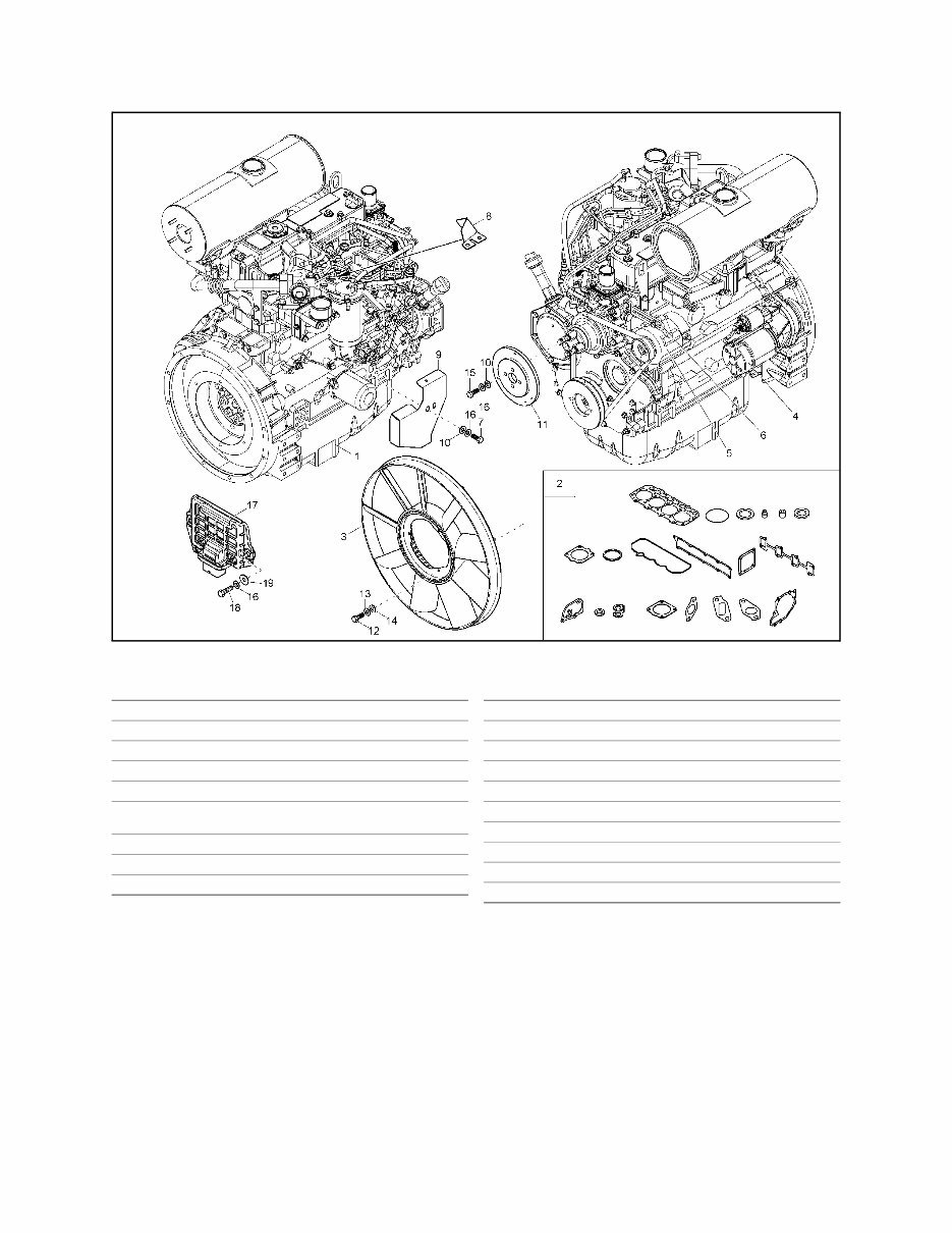
803 - DIESEL ENGINE - TIER III
1000180364 - (SN AH00611 AND UP)
Ref.
No. Part No. Description Qty.
1 203322 BASIC ENGINE 1
2 203323 SEAL KIT 1
3 205501 RADIATOR FAN 1
4 164382 STARTER 1
5 177631 ALTERNATOR 1
6 177560 CLAMP BAR/ALTERNATOR
ADJUSTING
1
7 656093 CS M8-1.25X16 C8.8 ZY DIN931 2
8 203324 COVER 1
9 203325 COVER 1
10 163634 WASHER 6
11 205502 SPACER 1
12 656149 CS M6-1X16 C8.8 ZY DIN931 3
13 161675 LOCKWASHER S6 3
14 161660 WASHER GR A6.4 ZO DIN 125 3
15 179784 SCREW 4
16 163670 LOCKWASHER 9
17 203326 DISTRIBUTOR 1
18 656105 CS M8-1.25X25 C8.8 ZY DIN931 3
19 7462680011 WASHER 8.4 ST A2C 3
Ref.
No. Part No. Description Qty.
You're Reading a Preview
What's Included?
Fast Download Speeds
Online & Offline Access
Access PDF Contents & Bookmarks
Full Search Facility
Print one or all pages of your manual
$27.99
Viewed 14 Times Today


Secure transaction
What's Included?
Fast Download Speeds
Online & Offline Access
Access PDF Contents & Bookmarks
Full Search Facility
Print one or all pages of your manual
$27.99
Gehl 803 parts manual is a fully illustrated parts list with exploded views, designed to assist in the disassembly and assembly process. It is a valuable resource for both professional mechanics and DIY enthusiasts. The manual covers serial numbers AC02528 and up and is the May 2008 edition.


