SHOP MANUAL model INDEX HYDRAULIC EXCAVATOR SPECIFICATIONS MAINTENANCE SYSTEM DISASSEMBLING TROUBLESHOOTING E/G OPT. 1 2 3 4 5 6 7 SPECIFICATIONS SECTION MAINTENANCE SECTION SYSTEM SECTION DISASSEMBLY SECTION TROUBLESHOOTING ENGINE SECTION PROCEDURE OF INSTALLING OPTIONS SECTION Book Code No.S5YN0042E01 0-1 SK210-9
GENERAL SAFETY INFORMATION Do not operate or perform any maintenance on this machine until all instructions found in the OPERA- TOR’S MANUAL and this MANUAL have been thor- oughly read and understood. Improper operation or maintenance of this machine may cause accidents and could result in serious in- jury or death. Always keep the manual in storage. If it is missing or damaged, place an order with an authorized Distributor for a replacement. If you have any questions, please consult an autho- rized Distributor. (1) Most accidents, which occur during operation, are due to neglect of precautionary measures and safe- ty rules. Sufficient care should be taken to avoid these accidents. Erroneous operation, lubrication or maintenance services are very dangerous and may cause injury or death to personnel. Therefore all precautionary measures, NOTES, DANGERS, WARNINGS and CAUTIONS contained in the man- ual and on the machine should be read and under- stood by all personnel before starting any work with or on the machine. (2) Operation, inspection, and maintenance should be carefully carried out, and safety must be given the first priority. Messages of safety are indicated with marks. The safety information contained in the manual is intended only to supplement safety codes, insurance requirements, local laws, rules and regulations. (3) Messages of safety appear in the manual and on the machine: All messages of safety are identified by one of the following words: "DANGER", "WARN- ING" and "CAUTION". 1) DANGER- Indicates an imminently hazardous situation which, if not avoided, will result in death or serious injury and is represented as follows: 2) WARNING- Indicates a potentially hazardous situation which, if not avoided, could result in death or serious injury and is represented as follows: 3) CAUTION- Indicates a potentially hazardous situation which, if not avoided, may result in mi- nor or moderate injury. It may also be used to alert against possible damage to the machine and its components and is represented as fol- lows: (4) It is very difficult to forecast every danger that may occur during operation. However, safety can be en- sured by fully understanding proper operating pro- cedures for this machine according to methods recommended by the Manufacturer. (5) While operating the machine, be sure to perform work with great care, so as not to damage the ma- chine, or allow accidents to occur. (6) Continue studying the manual until all Safety, Oper- ation and Maintenance procedures are completely understood by all persons working with the ma- chine.
SAFETY PRECAUTIONS The proper and safe lubrication and maintenance for this machine, recommended by the Manufactur- er, are outlined in the OPERATOR’S MANUAL for the machine. Improper performance of lubrication or mainte- nance procedures are dangerous and could result in injury or death. Read and understand the MANU- AL before performing any lubrication or mainte- nance. The serviceman or mechanic may be unfamiliar with many of the systems on this machine. This makes it important to use caution when performing service work. A knowledge of the system and/or components is im- portant before the removal or disassembly of any com- ponent. Because of the size of some of the machine compo- nents, the technician should check the weights noted in this manual. Use proper lifting procedures when remov- ing any component. The weight of components table is shown in section; SPECIFICATIONS. The following is a list of basic precautions that must al- ways be observed. (1) Read and understand all Warning plates and de- cals on the machine before Operating, Maintaining or Repairing this machine. (2) Always wear protective glasses and protective shoes when working around machines. In particu- lar, wear protective glasses when using hammers, punches or drifts on any part of the machine or at- tachments. Use welders gloves, hood/goggles, apron and the protective clothing appropriate to the welding job being performed. Do not wear loose fit- ting or torn clothing. Remove all rings from fingers, loose jewelry, confine long hair and loose clothing before working on this machine. (3) Disconnect the battery and hang a "Do Not Oper- ate" tag in the Operators Compartment. Remove ig- nition keys. (4) If possible, make all repairs with the machine parked on a firm level surface. Block the machine so it does not roll while working on or under the ma- chine. Hang a "Do Not Operate" tag in the Opera- tors Compartment. (5) Do not work on any machine that is supported only by a lift, jacks or a hoist. Always use blocks or jack stands capable of supporting the machine before performing any disassembly. Do not operate this machine unless you have read and understand the instructions in the OP- ERATOR’S MANUAL. Improper machine opera- tion is dangerous and could result in injury or death. (6) Relieve all pressure in air, oil or water systems be- fore any lines, fittings or related items are discon- nected or removed. Always make sure all raised components are blocked correctly and be alert for possible pressure when disconnecting any device from a system that utilizes pressure. (7) Lower the bucket, dozer, or other attachments to the ground before performing any work on the ma- chine. If this cannot be done, make sure the bucket, dozer, ripper or other attachment is blocked correct- ly to prevent it from dropping unexpectedly. (8) Use steps and grab handles when mounting or dis- mounting a machine. Clean any mud or debris from steps, walkways or work platforms before using. Al- ways face the machine when using steps, ladders and walkways. When it is not possible to use the designed access system, provide ladders, scaf- folds, or work platforms to perform safe repair oper- ations. (9) To avoid back injury, use a hoist when lifting com- ponents which weigh 20 kg (45 lbs) or more. Make sure all chains, hooks, slings, etc., are in good con- dition and are the correct capacity. Be sure hooks are positioned correctly. Lifting eyes are not to be side loaded during a lifting operation. (10)To avoid burns, be alert for hot parts on machines which have just been stopped and hot fluids in lines, tubes and compartments. (11)Be careful when removing cover plates. Gradually back off the last two capscrews or nuts located at opposite ends of the cover or device and carefully pry cover loose to relieve any spring or other pres- sure before removing the last two capscrews or nuts completely. (12)Be careful when removing filler caps, breathers and plugs on the machine. Hold a rag over the cap or plug to prevent being sprayed or splashed by liq- uids under pressure. The danger is even greater if the machine has just been stopped because fluids can be hot. (13)Always use the proper tools that are in good condi- tion and that are suited for the job at hand. Be sure
you understand how to use them before performing any service work. (14)Reinstall all fasteners with the same part number. Do not use a lesser quality fastener if replacements are necessary. (15)Repairs which require welding should be per- formed only with the benefit of the appropriate ref- erence information and by personnel adequately trained and knowledgeable in welding procedures. Determine the type of metal being welded and se- lect the correct welding procedure and electrodes, rods or wire to provide a weld metal strength equiv- alent at least to that of the parent metal. Make sure to disconnect battery before any welding proce- dures are attempted. (16)Do not damage wiring during removal operations. Reinstall the wiring so it is not damaged nor will be damaged in operation of the machine by contacting sharp corners, or by rubbing against some object or hot surface. Do not connect wiring to a hose or tube containing fluid. (17)Be sure all protective devices including guards and shields are properly installed and functioning cor- rectly before starting a repair. If a guard or shield must be removed to perform the repair work, use extra caution and replace the guard or shield after repair is completed. (18)The maintenance and repair work while holding the bucket raised is dangerous due to the possibility of a falling attachment. Don’t fail to lower the attach- ment and place the bucket to the ground before starting the work. (19)Loose or damaged fuel, lubricant and hydraulic lines, tubes and hoses can cause fires. Do not bend or strike high pressure lines or install ones which have been bent or damaged. Inspect lines, tubes and hoses carefully. Do not check for leaks with your hands. Very small (pinhole) leaks can result in a high velocity oil stream that will be invisible close to the hose. This oil can penetrate the skin and cause personal injury. Use card-board to locate pin- hole leaks. (20)Tighten connections to the correct torque. Make sure that all heat shields, clamps and guards are in- stalled correctly to avoid excessive heat, vibration or rubbing against other parts during operation. Shields that protect against oil spray onto hot ex- haust components in event of a line, tube or seal failure must be installed correctly. (21)Do not operate a machine if any rotating part is damaged or contacts any other part during opera- tion. Any high speed rotating component that has been damaged or altered should be checked for balance before reusing. (22)Be careful when servicing or separating the tracks (crawlers). Chips can fly when removing or install- ing a track (crawlers) pin. Wear safety glasses and long sleeve protective clothing. Tracks (crawlers) can unroll very quickly when separated. Keep away from front and rear of machine. The machine can move unexpectedly when both tracks (crawlers) are disengaged from the sprockets. Block the ma- chine to prevent it from moving.
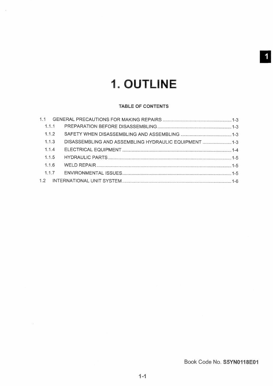
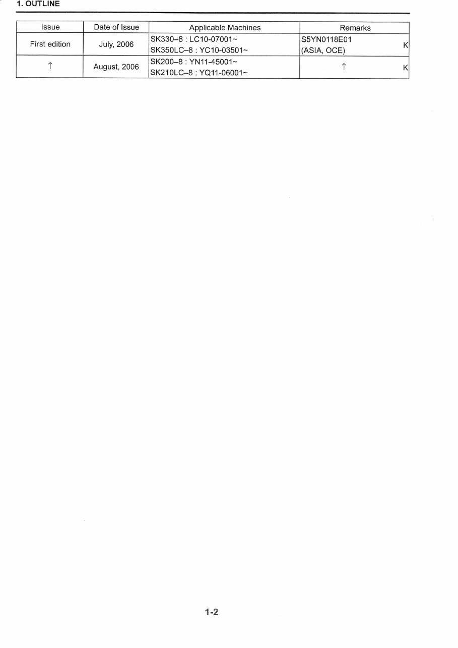
47 21 46 33 13 22 47 24 Index No. Title Book Code No. Distribution Year–Month S5LB1301E01 2011-03 S5YN2141E01 2011-03 S5YN2242E01 2011-03 S5YN2442E01 2011-03 _ _ S5YN3342E01 2011-03 S5YN4742E01 2011-03 _ _ YN13 S5LB4601E01 2011-03 MAINTENANCE STANDARD AND TEST PROCEDURE MECHATRO CONTROL SYSTEM 13 21 22 24 31 33 34 HYDRAULIC SYSTEM COMPONENTS SYSTEM UPPER STRUCTURE BY ERROR CODES BY TROUBLE APPLICABLE MACHINES SPECIFICATIONS MAINTENANCE SYSTEM DISASSEMBLING TROUBLESHOOTING E/G INDEX SK210-9 NA 46 47 S5YN0118E01 2006-8 OUTLINE S5YN0218E02 2007-2 SPECIFICATIONS S5YN0318E01 2006-8 ATTACHMENT DIMENSIONS S5YN1118E02 2008-10 TOOLS S5YN1218E01 2006-8 STANDARD MAINTENANCE TIME SCHEDULE S5YN2318E02 2007-2 ELECTRIC SYSTEM S5YN2518E02 2007-2 AIR-CONDITIONER SYSTEM _ S5YN3118E01 2006-8 DISASSEMBLING & ASSEMBLING S5YN3218E02 2007-2 ATTACHMENT S5YN3418E02 2007-2 TRAVEL SYSTEM S5YN4818E01 2006-8 TROUBLE DIAGNOSIS MODE 84392428 2011-04 ENGINE 1 2 3 11 12 23 25 31 32 34 48 51
NOTE: This Manual is prepared as a technical material in which the information necessary for the maintenance and repairing services of our hydraulic excavators are collected, and is categorized into 7 Chapters, Specifica- tion, Maintenance, System, Disassembly, Trouble- shooting, Engine, and Installation Procedures for Optional Attachments. • The Chapter "Specification" describes the specifi- cations for entire machine and material, which are instructive for replacement and repairing of attach- ments. • The Chapter "Maintenance" describes the material, which is helpful for maintenance service and adjust- ments for the entire machine. • The Chapter "System" describes the operating sys- tem like hydraulic system, electric system, compo- nents, and so on. • The Chapter "Disassembly" describes the removal and installing of assemblies mounted on the upper structure and undercarriage, and the assembling and disassembling of the associated hydraulic equipment. • The Chapter "Troubleshooting" describes how to find the equipment fault. • The Chapter "Engine" describes the engines mak- ing use of the "Maintenance Manual" provided by the suppliers. • The Chapter "Installation Procedures for Optional Attachment" describes the supplements added on request as required. This Manual may be properly revised due to the im- provement of products, modification of specifications, etc. And there are cases where the system on the actu- al machine and a part of the contents of this manual may differ due to the variations of specifications by countries. For the section in which the description is hardly understood, contact our distributor. A number is assigned to every part handled in this Man- ual on account of the description, but the parts cannot be supplied as service parts. Therefore, the order must be placed with the respective formal number with con- firmation from the Parts Manual for the applicable ma- chine.
The Kobelco SK210-9 Excavators Repair Manual is an essential resource for maintaining and repairing this powerful machine. Whether you're a professional mechanic or a dedicated DIY enthusiast, this workshop manual is designed to meet your needs.
Inside this manual, you'll discover detailed instructions for the removal, installation, disassembly, and assembly of all the components of the SK210-9 Excavator. Say goodbye to guesswork and struggles in figuring out component assembly - this manual offers clear and concise explanations.
Moreover, the manual includes an electrical wiring diagram and hydraulic schematic, providing invaluable assistance in troubleshooting any electrical or hydraulic issues that may arise. The step-by-step instructions empower you to diagnose and resolve problems with confidence.
Furthermore, this manual not only delivers comprehensive repair information but also incorporates crucial specifications and torque values. This ensures that you utilize the correct settings and measurements for optimal performance.







 Lifetime Access




