CRAWLER EXCAVATOR CX210B-CX230B-CX240B SERVICE MANUAL TABLE OF CONTENTS DIVISION/SECTION SECTION N° REFERENCE N° 1 GENERAL INFORMATION Safety, general information and standard torque data .....................................1001 7-27691EN General specifications and special torque setting............................................1002 SC210B1002-0EN 2 ENGINE Removal and installation of the engine ............................................................2000 SM210B2000-0EN Radiator and oil-cooler .....................................................................................2001 SM210B2001-0EN Engine specifications ............................................................................................. * Disassembly and assembly of the engine .............................................................. * 3 FUEL SYSTEM Fuel tank ..........................................................................................................3001 SM160B3001-0EN Fuel engine system ................................................................................................ * 4 ELECTRICAL SYSTEM Electrical system, electrical and electronic troubleshooting .............................4001 SC210B4001-1EN Electrical equipment and electrical circuit diagrams ........................................4020 SC210B4020-0EN 5 UNDERCARRIAGE Removal and installation of tracks ...................................................................5001 SM160B5001-0EN Rollers .............................................................................................................5003 SM160B5003-0EN Sprocket ...........................................................................................................5004 SM160B5004-0EN Idler wheel and tension shock absorber ..........................................................5005 SM160B5005-0EN 6 DRIVE TRAIN Drive motor and final drive transmission removal and installation ...................6001 SM160B6001-0EN Drive motor and final drive transmission disassembly and assembly ..............6002 SM160B6002-0EN Swing reduction gear, removal and installation ................................................6003 SM160B6003-0EN Swing reduction gear, disassembly and assembly (CX210B - CX230B) .........6004 SM210B6004-0EN Swing reduction gear, disassembly and assembly (CX240B) ..........................6004 SM240B6004-0EN 7 UNDERCARRIAGE HYDRAULICS 8 UPPERSTRUCTURE HYDRAULICS Depressurising and decontaminating the hydraulic system, use of the vacuum pump and bleeding the components ..............................................8000 SM160B8000-0EN Specifications, troubleshooting, checks and hydraulic pressure settings.........8001 SC210B8001-2EN Hydraulic reservoir removal and installation ...................................................8002 SM160B8002-0EN Main and hydraulic pilot pumps, removal and installation ..............................8003 SM210B8003-0EN Main hydraulic control valve, removal and installation ....................................8004 SM210B8004-0EN Attachment cylinders, removal and installation ...............................................8005 SM160B8005-0EN Hydraulic swivel, removal and installation .......................................................8006 SM160B8006-0EN Pilot blocs, removal and installation .................................................................8007 SM160B8007-0EN Swing motor, removal and installation..............................................................8008 SM160B8008-0EN Main hydraulic pump, disassembly and assembly ...........................................8010 SM210B8010-0EN Main hydraulic pump, disassembly and assembly (CX210B NLC) ..................8010 SM210BNLC8010-0EN Hand control levers, disassembly and assembly .............................................8013 SM160B8013-0EN Foot control levers, disassembly and assembly ...............................................8014 SM160B8014-0EN Caution valve, disassembly and assembly.......................................................8016 SM160B8016-0EN Swing motor, disassembly and assembly (CX210B - CX230B) .......................8019 SM160B8019-0EN Swing motor, disassembly and assembly (CX240B)........................................8019 SM240B8019-0EN Hydraulic functions...........................................................................................8020 SC210B8020-1EN Hydraulic component functions ........................................................................8030 SC210B8030-0EN
Lep SM210BTOC-0EN Issued 05-07 DIVISION/SECTION SECTION N° REFERENCE N° 9 UPPERSTRUCTURE Quick coupler ..................................................................................................... 9000 SM160B9000-0EN Upperstructure, turntable and counterweight ..................................................... 9002 SM160B9002-0EN Boom, dipper and bucket ................................................................................... 9003 SM160B9003-0EN Seat, removal and installation ............................................................................ 9004 SM160B9004-0EN Cab and cab equipment..................................................................................... 9005 SM160B9005-0EN Air conditioner functions and troubleshooting .................................................... 9006 SC210B9006-0EN Large size hydraulic schematics CX210B-CX230B .........................................Pocket 87598349A Large size hydraulic schematics CX240B........................................................Pocket 87600987A Large size electrical schematics ......................................................................Pocket 87598355A * Consult the Engine Service Manual NOTE: CNH Company reserves the r ight to make changes in the specifica tion and design of the machine without prior notice and without incurring any obliga- tion to modify units previously sold. The description of the models shown in this manual has been made in acco rd- ance with the technical specifications known as of the date of design of this document.
CNH Lep 7-27691EN 1001 SAFETY, GENERAL INFORMATION AND TORQUE SPECIFICATIONS Section 1001
1001-2 Lep 7-27691EN Issued 02-06 TABLE OF CONTENTS GENERAL INFORMATION ....................................................................................................................................... 3 SAFETY..................................................................................................................................................................... 4 STANDARD TORQUE DATA FOR CAP SCREWS AND NUTS............................................................................... 6 WARNING : This symbol is used in this manual to indicate important safety messages. Whenever you see this symbol, carefully read the message that follows, as there is a risk of serious injury. !
1001-3 Lep 7-27691EN Issued 02-06 GENERAL INFORMATION Cleanning Clean all metal par ts except bear ings, in a suitab le cleaning so lvent or b y ste am clea ning. Do not use caustic sod a f or st eam clean ing. After clea ning, dry and put o il on al l pa rts. Clea n o il p assages with compressed air. Clean bearings in a suitable cleaning solvent, dry th e be arings completely an d pu t oil on the bearings. Inspection Check a ll parts whe n th e pa rts ar e disassemb led. Replace a ll pa rts t hat h ave wear o r d amage. Small scoring or g rooves can be r emoved wit h a ho ne o r crocus clot h. Com plete a visual in spection for indications of w ear, p itting an d the r eplacement o f parts necessary to prevent early failures. Bearings Check b earings f or easy actio n. If be arings ha ve a loose f it or ro ugh act ion r eplace t he bea ring. W ash bearings wit h a suitable cle aning solvent a nd p ermit to air dr y. DO NO T DR Y BEARIN GS WITH COMPRESSED AIR. Needle bearings Before you pr ess nee dle bearings in a bore always remove any metal protrusions in the bore or edge of the bore. Before you press bearings into position put petroleum jelly on the inside and outside diameter of the bearings. Gears Check all gears for wear and damage. Replace gears that have wear or damage. Oil seals, O-rings and gaskets Always install new oil seals, O-rings and gaskets. Put petroleum jelly on seals and O-rings. Shafts Check all shaf ts t hat have w ear or dam age. Ch eck the bearing a nd oil seal surfaces of t he sha fts f or damage. Service parts Always install gen uine Case ser vice par ts. When ordering refer to the Parts Catalog for the correct part number of t he g enuine Case r eplacement ite ms. Failures due to the use of other than ge nuine Ca se replacement parts are not covered by warranty. Lubrication Only use t he o ils and lubr icants spe cified in t he Operator’s or Service Ma nuals. Failures du e to th e use o f no n-specified o ils an d lub ricants are not covered by warranty.
1001-4 Lep 7-27691EN Issued 02-06 SAFETY This symbol means ATTENTION! BECOME ALERT! YOUR SAFETY IS INVOLVED. The message that follows the symbol contains important information about safety. Carefully read the message. Make sure you fully understand the causes of possible injury or death. ! To prevent injur y always follow the Warning, Caution and Danger notes in t his section and throughout the manual. Put the warning tag shown below on the key for the keyswitch w hen ser vicing or repairing the machine . One warning t ag is supplied with ea ch m achine. Additional ta gs Part Numb er 331-4614 are available from your service parts supplier . WARNING: Read the operator’s manual to familiarize yourself with the correct control functions. ! WARNING: Operate the machine and equipment controls from the seat position only. Any other method could result in serious injury. ! WARNING: This is a one man machine, no riders allowed. ! WARNING: Before starting engine, study Operator’s Manual safety messages. Read all safety signs on machine. Clear the area of other persons. Learn and practice safe use of controls before operating. It is your responsibility to understand and follow manufacturers instructions on machine operation, service and to observe pertinent laws and regulations. Operator’s and Service Manuals may be obtained from your Case dealer. ! WARNING: If you wear clothing that is too loose or do not use the correct safety equipment for your job, you can be injured. Always wear clothing that will not catch on objects. Extra safety equipment that can be required includes hard hat, safety shoes, ear protection, eye or face protection, heavy gloves and reflector clothing. ! WARNING: When working in the area of the fan belt with the engine running, avoid loose clothing if possible, and use extreme caution. ! WARNING: When doing checks and tests on the equipment hydraulics, follow the procedures as they are written. DO NOT change the procedure. ! WARNING: When putting the hydraulic cylinders on this machine through the necessary cycles to check operation or to remove air from a circuit, make sure all people are out of the way. !
1001-5 Lep 7-27691EN Issued 02-06 WARNING: Use insulated gloves or mittens when working with hot parts. ! WARNING: Lower all attachments to the ground or use stands to safely support the attachments before you do any maintenance or service. ! WARNING: Pin sized and smaller streams of hydraulic oil under pressure can penetrate the skin and result in serious infection. If hydraulic oil under pressure does penetrate the skin, seek medical treatment immediately. Maintain all hoses and tubes in good condition. Make sure all connections are tight. Make a replacement of any tube or hose that is damaged or thought to be damaged. DO NOT use your hand to check for leaks, use a piece of cardboard or wood. ! WARNING: When removing hardened pins such as a pivot pin, or a hardened shaft, use a soft head (brass or bronze) hammer or use a driver made from brass or bronze and a steel head hammer. ! WARNING: When using a hammer to remove and install pivot pins or separate parts using compressed air or using a grinder, wear eye protection that completely encloses the eyes (approved goggles or other approved eye protectors). ! WARNING: Use suitable floor (service) jacks or chain hoist to raise wheels or tracks off the floor. Always block machine in place with suitable safety stands. ! WARNING: When servicing or repairing the machine, keep the shop floor and operator’s compartment and steps free of oil, water, grease, tools, etc. Use an oil absorbing material and/or shop cloths as required. Use safe practices at all times. ! WARNING: Some components of this machine are very heavy. Use suitable lifting equipment or additional help as instructed in this Service Manual. ! WARNING: Engine exhaust fumes can cause death. If it is necessary to start the engine in a closed place, remove the exhaust fumes from the area with an exhaust pipe extension. Open the doors and get outside air into the area. ! WARNING: When the battery electrolyte is frozen, the battery can explode if (1), you try to charge the battery, or (2), you try to jump start and run the engine. To prevent the battery electrolyte from freezing, try to keep the battery at full charge. If you do not follow these instructions, you or others in the area can be injured. !
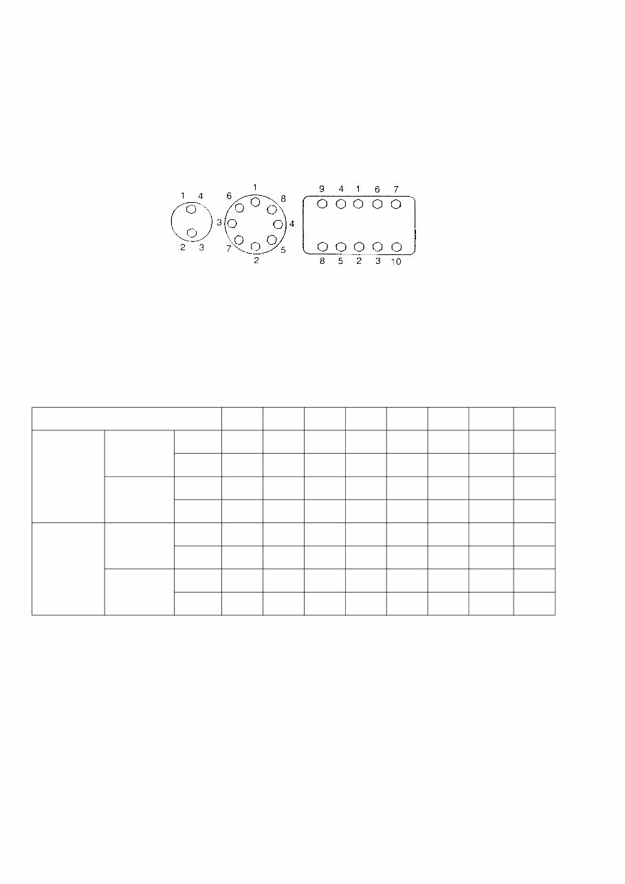
1001-6 Lep 7-27691EN Issued 02-06 STANDARD TORQUE DATA FOR CAP SCREWS AND NUTS Tightening of cap screws, nuts Tighten alternately so that tightening torque can be applied evenly. The numbers in the figure below indicate the order of tightening. JS00481A Cap screws which have had Loctite used (white residue remains after removal) should be cleaned with loght oil or suitable cle aning solv ent and dr ied. Apply 2- 3 d rops of Lo ctite t o t he th read p ortion o f th e cap scre w an d t hen tighten. Torque table Tighten cap screws and nuts according to the table below if there are no other special instructions. Cap Screw Name Size (Size) M6 M8 M10 M12 M14 M16 M18 M20 Cap Screw Spanner [mm] 10 13 17 19 22 24 27 30 [in.] 0.39 0.51 0.67 0.75 0.87 0.95 1.06 1.18 Tightening torque [Nm] 6.9 19.6 39.2 58.8 98.1 156.9 196.1 294.2 [lb-ft] 5.1 14.5 28.9 43.4 72.3 115.7 144.6 217 Socket Head Cap Screw Spanner [mm] 5 6 8 10 12 14 14 17 [in.] 0.20 0.24 0.32 0.39 0.47 0.55 0.55 0.67 Tightening torque [Nm] 8.8 21.6 42.1 78.5 117.7 176.5 245.2 343.2 [lb-ft] 6.5 15.9 31.1 57.9 86.9 130.2 181 253.2
CNH Lep SC210B1002-0EN 1002 SPECIFICATIONS AND SPECIAL TORQUE SETTINGS Section 1002
Lep SC160B1002-0EN Issued 02-07 1002-2 TABLE OF CONTENTS TYPE, SERIAL NUMBER AND YEAR OF MANUFACTURE OF THE MACHINE..................................................................................................... 3 Machine ....................................................................................................................................................................... 3 Engine .......................................................................................................................................................................... 3 Serial numbers of the components .............................................................................................................................. 3 FLUIDS AND LUBRICANTS ............................................................................................................................................ 4 Hydraulic fluid .............................................................................................................................................................. 4 Transmission component oil ........................................................................................................................................ 4 Grease ......................................................................................................................................................................... 4 Engine Oil .................................................................................................................................................................... 5 Engine fuel, maintenance of fuel filters and fuel storage ............................................................................................. 6 Anti-freeze/Anti-corrosion............................................................................................................................................. 8 Environment ................................................................................................................................................................. 8 Plastic and resin parts .................................................................................................................................................. 8 SPECIFICATIONS ........................................................................................................................................................... 9 Main data ..................................................................................................................................................................... 9 Performance ................................................................................................................................................................ 9 Complete machine dimensions .................................................................................................................................. 10 Main body dimensions ............................................................................................................................................... 12 Engine ........................................................................................................................................................................ 13 Cooling system .......................................................................................................................................................... 13 Capacity of coolant and lubricants ............................................................................................................................. 13 Hydraulic oil filter ........................................................................................................................................................ 14 Fuel filter .................................................................................................................................................................... 14 Operating devices ...................................................................................................................................................... 14 Hydraulic system........................................................................................................................................................ 15 Swing unit .................................................................................................................................................................. 18 Travel lower body ....................................................................................................................................................... 19 Work Unit ................................................................................................................................................................... 20 Digging force (ISO 6015) ........................................................................................................................................... 29 COMPONENT WEIGHT................................................................................................................................................. 30 Major component weight ............................................................................................................................................ 30 Other component weight ............................................................................................................................................ 32 SPECIAL TORQUE SETTINGS ..................................................................................................................................... 34 MACHINE OVERALL DIMENSIONS ............................................................................................................................. 38 WARNING: This symbol is used in this manual to indicate important safety messages. Whenever you see this symbol, carefully read the message which follows. Your safety depends on it. !
You're Reading a Preview
What's Included?
Lifetime Access
Fast Download Speeds
Online & Offline Access
Access PDF Contents & Bookmarks
Full Search Facility
Print one or all pages of your manual
$81.99
CASE CX210B MH CX210B SL Crawler Excavator Service Repair Manual
The CX210B MH CX210B SL Crawler Excavator Service Repair Manual is a comprehensive guide containing detailed information, diagrams, and actual photo illustrations. It provides step-by-step operations for repair, servicing, technical maintenance, and troubleshooting procedures for your machine. This manual is essential for professionals and DIY enthusiasts alike, offering complete information for machine repair and maintenance.
The manual covers the following sections:
SECTION 01 - GENERAL INFORMATION
SECTION 02 - ENGINE
SECTION 03 - FUEL SYSTEM
SECTION 04 - ELECTRICAL SYSTEM
SECTION 05 - UNDERCARRIAGE
SECTION 06 - DRIVE TRAIN
SECTION 07 - UNDERCARRIAGE HYDRAULICS
SECTION 08 - UPPERSTRUCTURE HYDRAULICS
SECTION 09 - UPPERSTRUCTURE
The mounted engine for this manual is the ISUZU 4HK1, and it is applicable to all serial numbers. The manual is in English language, with a file format of .PDF and a size of 184Mb spanning 1669 pages. It also includes electrical and hydraulic schematics.
With the convenience of digital format, you can utilize the search feature in Acrobat to quickly find the information you need and print specific pages as required. This manual is available for instant download after payment, providing a space-saving and efficient solution for your repair needs.
If you have any questions or require a service manual for engine repair, feel free to reach out. We may have the manual you've been searching for. Have a great day!
Reviews
Q&A
Recently Viewed
5,521,897Happy Clients
2,594,462eManuals
1,120,453Trusted Sellers
15Years in Business
Price:
Actual Price:
CASE CX210B MH CX210B SL Crawler Excavator Service Repair Manual










 Lifetime Access




