CX17B EXCAVATORS OPERATOR’S MANUAL NOTE: CNH America LLC reserves the right to make improvements in design or changes in specifications at any time without incurring any obligation to install them on units previously sold. CNH AMERICA LLC TECHNICAL MANUALS Manuals are available from your Dealer for the operation, service, and repair of your machine. For prompt convenient service, contact your Dealer for assistance in obtaining the manuals for your machine. Your Dealer can expedite your order for Operator’s Manuals, Parts Catalogs, Service Manuals, and Maintenance records. Always give the Machine Name, Model, and P.I.N. (Product Identification Number) or S.N. (Serial Number) of your machine so your Dealer can provide the correct manuals for your machine. Part Number: 87364366
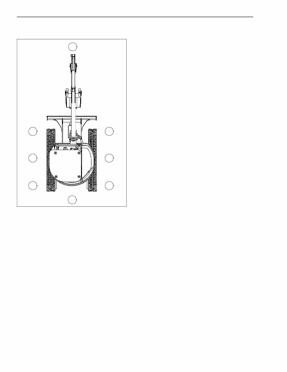
CHAPTER 1 - GENERAL INFORMATION 1-1 87364366NA Issued 03-07 Bur Chapter 1 GENERAL INFORMATION TO THE OWNER CX SERIES COMPACT HYDRAULIC CRAWLER EXCAVATOR Your machine has been designed and built to the highest standards of quality. It conforms to all current safety regulations. See Official documents. However, the risk of accidents can never be completely excluded. That is why it is essential to observe elementary safety rules and precautions. Read this manual carefully, paying particular attention to the instructions concerning safety, operation and maintenance so as to avoid the risk of injury while operating or servicing the machine. The standard attachments and tools of this machine are designed to carry out all kinds of earthmoving and rehandling operations. If you want to use this machine to handle a load (pipes, culverts, formwork, etc.), make sure that it is designed to carry out this kind of work. For this type of application, the machine must be equipped with safety valves, an overload indicator, a load handling chart corresponding to the type of machine and its attachment and a load fixing point. All legal requirements must also be strictly observed. Do not use this machine for any application or purpose other than those described in this manual. If the machine is to be used for work involving the use of special attachments, accessories or equipment, consult your Dealer in order to make sure that any adaptations or modifications made are in keeping with the machine's technical specifications and with prevailing safety requirements. Any modification or adaptation which is not approved by the manufacturer may invalidate the machine's initial conformity with safety requirements. The machine must undergo regular inspections, the frequency of which varies according to the type of use. Consult your Dealer. Before permitting a new operator on this machine, make sure: That the operator has received the necessary training on how to operate the machine correctly and safely. That the operator has read and understood the instructions given in this manual. Always keep this manual in the operator's compartment (in the seat back, behind the operator's seat). Make sure it is always complete and in good condition. If you wish to obtain extra copies, or copies in languages other than that of the country of use, consult your Dealer. Your Dealer is at your disposal for any further information. He will also provide any after-sales service you may require, and genuine Case spare parts, your guarantee of quality and match. The terms Right-hand, Left-hand, Front, and Rear are used in this manual to indicate the sides as they are seen from the operator's seat when the cab is over the idler wheels. The illustration shows the machine in normal TRAVEL position. In normal TRAVEL position, the cab is over the idler wheels. The travel reduction gears are at the rear of the upper structure.
CHAPTER 1 - GENERAL INFORMATION 1-2 Issued 03-07 Bur 87364366NA RIGHT, LEFT, FRONT, AND REAR OF THE MACHINE BC02N192 Figure 1 1. FRONT 2. REAR 3. RIGHT-HAND SIDE 4. LEFT-HAND SIDE 5. TRAVEL REDUCTION GEARS (TRAVEL MOTORS) 6. IDLER WHEELS The CX compact excavator is a fully hydraulic machine. It consists of an undercarriage fitted with tracks and a turntable bearing which supports the upperstructure frame. The upperstructure frame supports the attachment, at the front end of the machine, plus the engine, hydraulics and cab. When the operator works the controls, the engine-driven pump delivers hydraulic fluid to the control valves. The control valves distribute the hydraulic fluid to the various cylinders and motors concerned. A cooling system maintains the hydraulic fluid at normal operating temperature. 1 6 6 3 4 5 5 2
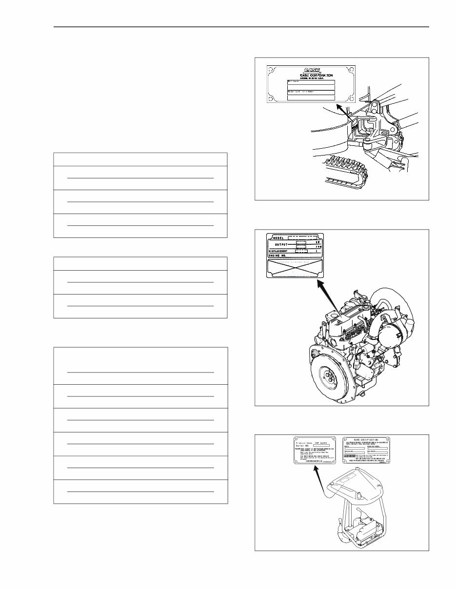
CHAPTER 1 - GENERAL INFORMATION 1-3 87364366NA Issued 03-07 Bur IDENTIFICATION NUMBERS MODEL, SERIAL NUMBER, AND YEAR OF MANUFACTURE When ordering parts, obtaining information or assistance, always supply your Dealer with the type and serial number of your machine or accessories. Write the following in the spaces below: The type, serial number and year of manufacture of your machine, accessories and the serial numbers of the various hydraulic and mechanical components. COMPONENT SERIAL NUMBERS BS04H224 Figure 1 ENGINE UPU00000002JS1 Figure 2 ROPS CERTIFICATION UPU00000001ES1 Figure 3 PRODUCT IDENTIFICATION PLATE ➤ Model ➤ Serial Number ➤ Manufacturing Year ENGINE ➤ Make and Model ➤ Serial Number COMPONENT SERIAL NUMBERS ➤ Hydraulic Pump ➤ Swing Reduction Gear ➤ Travel Reduction Gears ➤ Travel Control Valve ➤ Attachment Control Valve ➤ Swing Control Valve
CHAPTER 1 - GENERAL INFORMATION 1-4 Issued 03-07 Bur 87364366NA NOTES
This complete manual for the Case CX17B Tier 4 hydraulic excavator provides detailed instructions, diagrams, and illustrations based on the manufacturer's specifications. It is an operator's manual, also known as an instruction, owner, or user manual, covering various aspects of operating and maintaining the machine.
The manual is improved with bookmarks, searchable text, an index, and enhanced quality. It is instantly accessible and compatible with all versions of Windows, Mac, iOS, BB, Android, etc. The content includes general information, safety, decals, hand signals, instruments, controls, operating instructions, lubrication, filters, fluids, maintenance, adjustments, electrical, specifications, and more.
It is designed to be easily searchable and bookmarked, allowing users to find information quickly. The manual is in a format that is easy to read, view, zoom, print, and save on any computer. It contains numerous pictures, diagrams, illustrations, and charts, along with technical details and instructions for both professional mechanics and DIY enthusiasts.
For those interested in obtaining this manual, it is available for immediate access without the need to worry about missing or damaged pages. It is recommended to have the latest version of Acrobat Reader for optimal viewing of the document. For any inquiries about other manuals, feel free to reach out for further assistance.