

HYDRAULICS EXCA
HYDRAULICS EXCA
V
V
A
A
TORS
TORS
"
"
1
1
2
2
8
8
8
8
&
&
1
1
4
4
8
8
8
8
C
C
"
"
08 - 1998
English version
Reproduction , réimpression et traduction, même partielles sont interdites sans une
autorisation spéciale de nos services
Centre de formation


1-1
CASE
Issued 11-97 Printed in England Mon 1288/1488 GB
Training Center
BASIC PRINCIPLES OF ELECTRONICALLY ASSISTED SYSTEMS
CONTENTS PAGE
STARTING ASSISTANCE ........................................................................................1.02.00
ELECTRIC ACCELERATION ....................................................................................1.04.00
AUTOMATIC RETURN TO IDLE ..............................................................................1.05.00
ENGINE OVERHEATING SAFETY DEVICE ............................................................1.06.00
SPEED-SENSING SYSTEM ..................................................................................1.07.00
SWING BREAK RELEASE ......................................................................................1.08.00
SWING BREAK ........................................................................................................1.09.00
AUTOMATIC TRAVEL SEQUENCES
FOR TWO-SPEED EXCAVATORS ..........................................................................1.12.00
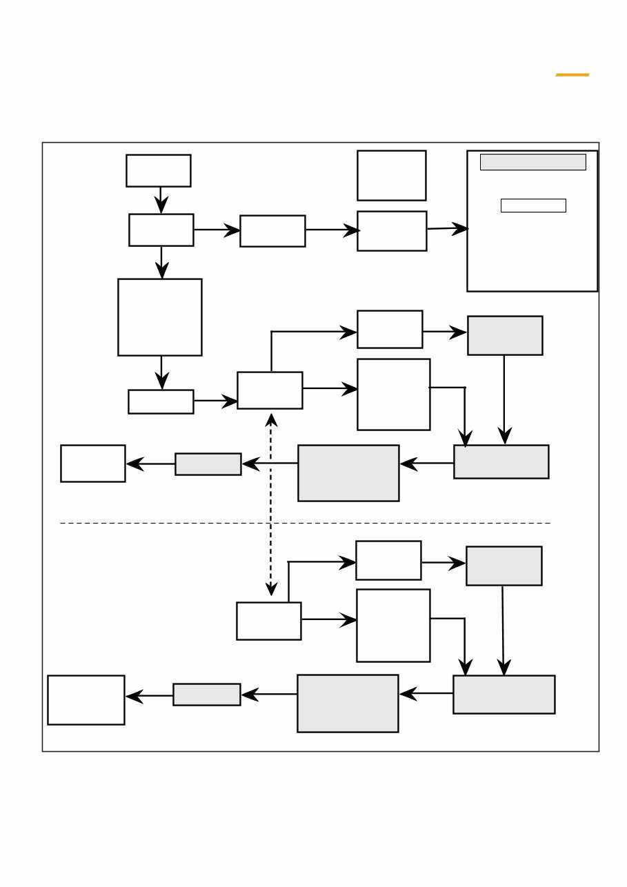
Servo-motor on
the injection
pump goes to
ECO mode and
then comes
back to
Master
switch
Starts
Temp sensor
on engine
block
Ignition
key
Buzzer
sounds
Automatic
stop
t = 2 s
If does not start
- Safety indicator lamps
light up
- The hydraulic filter and air
filter indicator lamps
go out
- Buzzer sounds again
- Use push-button to stop
After 30 sec.
Manual
push-button
shut-down
Engine
speed
1200 r.p.m.
Water temp
lower than
60¡ C
PRE-HEATING LED
on control box
flashes
Servo-motor
Electronic control
housing
Engine
speed 1200
r.p.m.
Temp sender
on engine
block
Engine
speed 1200
r.p.m.
Water temp
higher than
60¡ C
Time with
engine speed
at 1200 r.p.m.
over
5 mn.
PRE-HEATING LED
on control box goes
out
Servo-motor
Electronic control
box
Select desired
engine speed
Time with
engine speed
1200 r.p.m.
less
than 5 mn
STARTING ASSISTANCE
Mon 1288/1488 GB Issued 11-97 Printed in England
1 -2
CASE
Training Center
BASIC PRINCIPLES OF ELECTRONICALLY ASSISTED SYSTEMS
PURPOSE:
When the engine is switched on, the system provides:
- A pre-opening of the injection pump
- Automatic return of injection pump to the high idle position.
WORKING PRINCIPLES
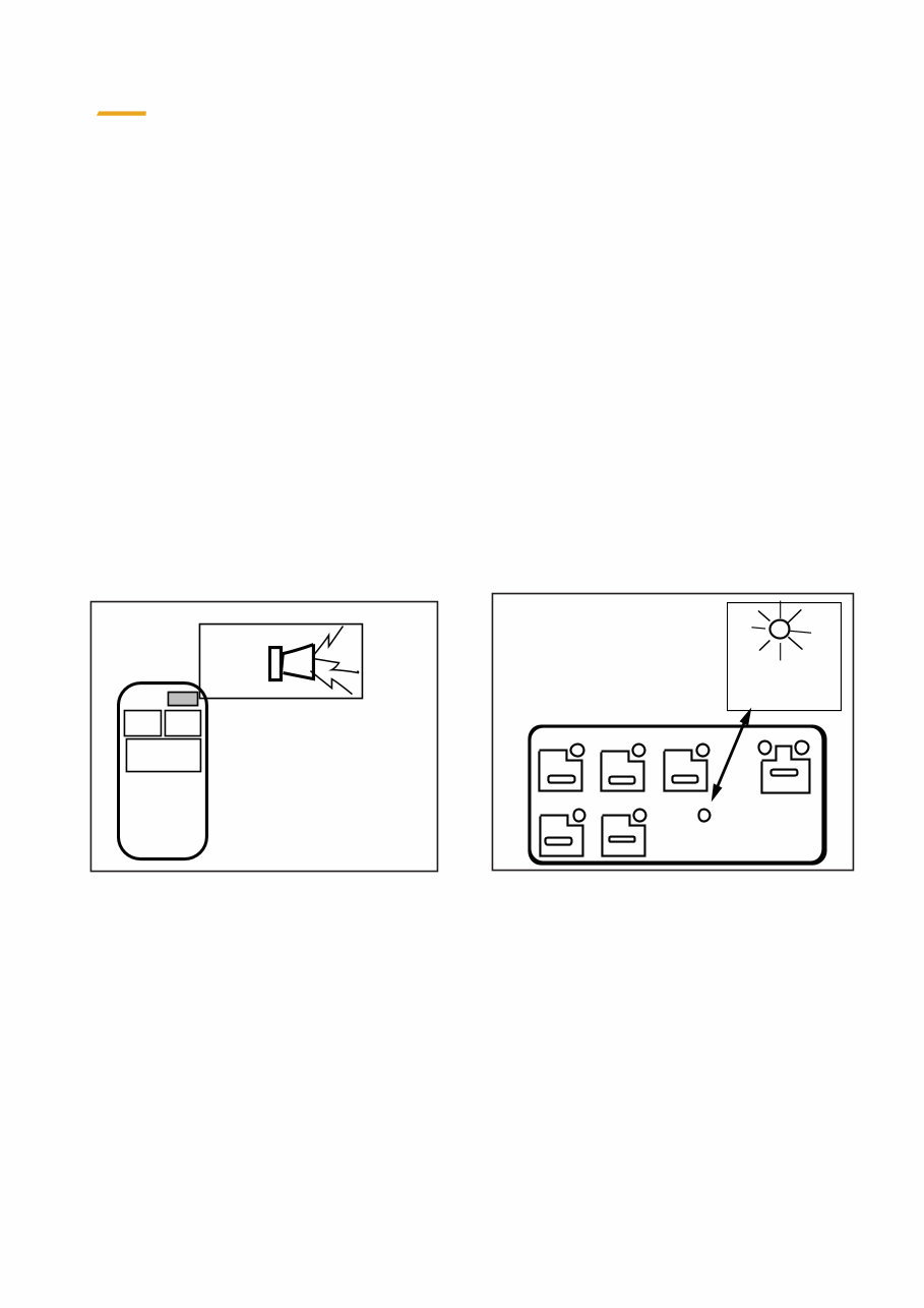
- When the system is switched on using the ignition key, the buzzer sounds. The buzzer stops automatically
after two seconds.
- If the engine does not start, the following warning lamps come on:
battery charge, engine oil pressure, minimum pilot pressure, air filter and oil filter restriction warning.
After 30 seconds, the last two warning lamps go out and the buzzer sounds (the buzzer can be turned off by the
push-button on the instrument panel)
- If the engine starts, the injection pump servo-motor, which is in ECO MODE speed position, cuts in to provide
an engine speed of 1200 rpm (high idle)..
- if the engine coolant water temperature is lower than 60¡C or if the time that the motor runs at 1200 rpm is less
than 5 minutes, the electronic system will not permit changing to the LOW, FINE, ECO or MAX modes.
This is indicated by the PRE-HEATING indicator which has a flashing indicator lamp (LED).
STOP
1-3
CASE
Issued 11-97 Printed in England Mon 1288/1488 GB
Training Center
BASIC PRINCIPLES OF ELECTRONICALLY ASSISTED SYSTEMS
HEATING
PRE
FINE ECO MAXI 1
TRAVEL
2
IDLE
LOW
IDLE
AUTO
HEATING
PRE
Location of PRE-HEATING
indicator lamp
Location of buzzer
stop push-button
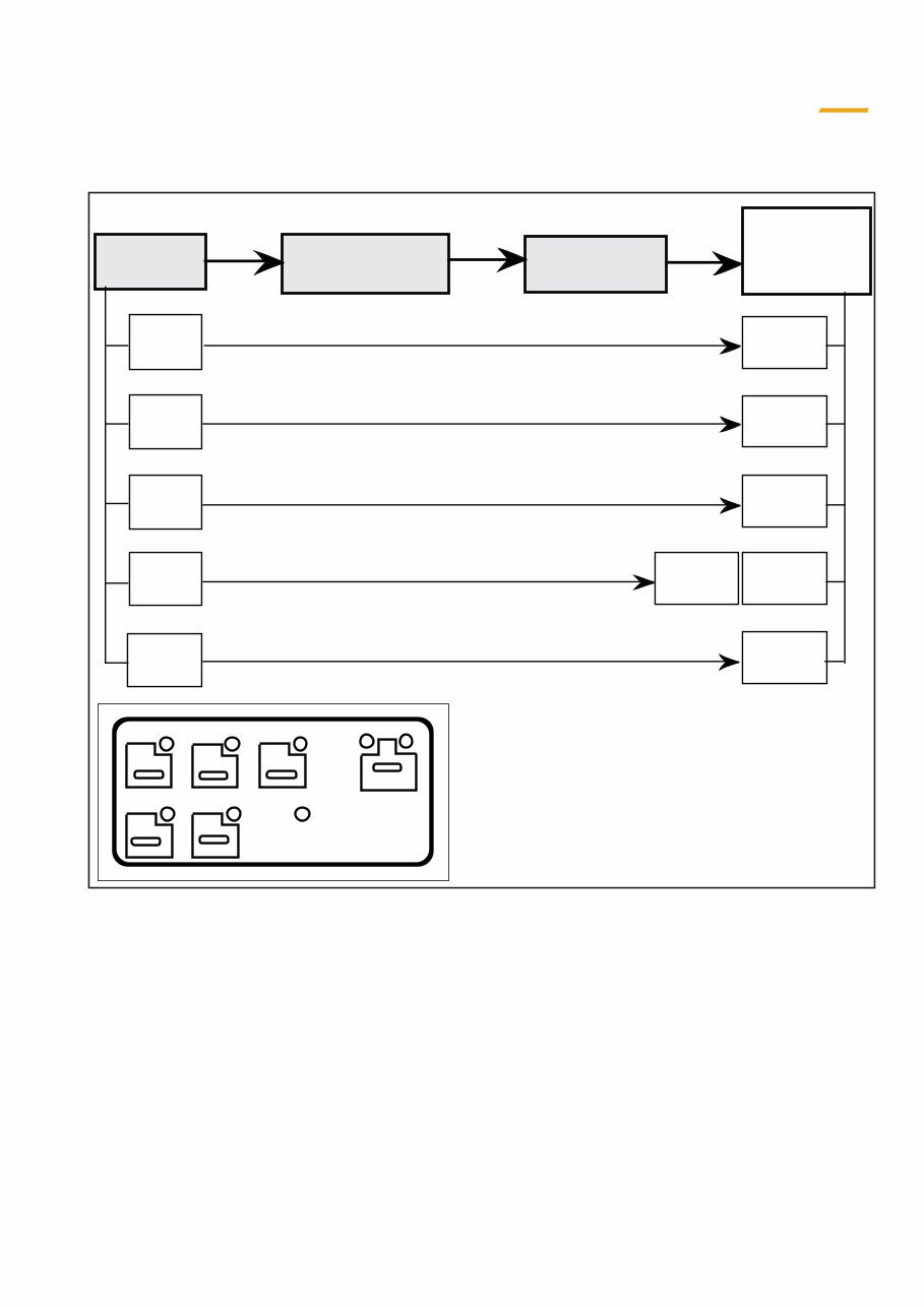
ASSISTANCE FOR STARTING
950
r.p.m.
Control box Servo-motor
Engine speed
depending
mode
selected
LOW
IDLE
1200
r.p.m.
AUTO
IDLE
1600
r.p.m.
FINE
ECO
2270
r.p.m.
MAX
Electronic control
box
1950
tr/mn
1850
tr/mn
1 1 2 2 8 8 8 8 1 1 4 4 8 8 8 8
Mon 1288/1488 GB Issued 11-97 Printed in England
1 -4
CASE
Training Center
BASIC PRINCIPLES OF ELECTRONICALLY ASSISTED SYSTEMS
FINE ECO MAXI 1
TRAVEL
2
IDLE
LOW
IDLE
AUTO
HEATING
PRE
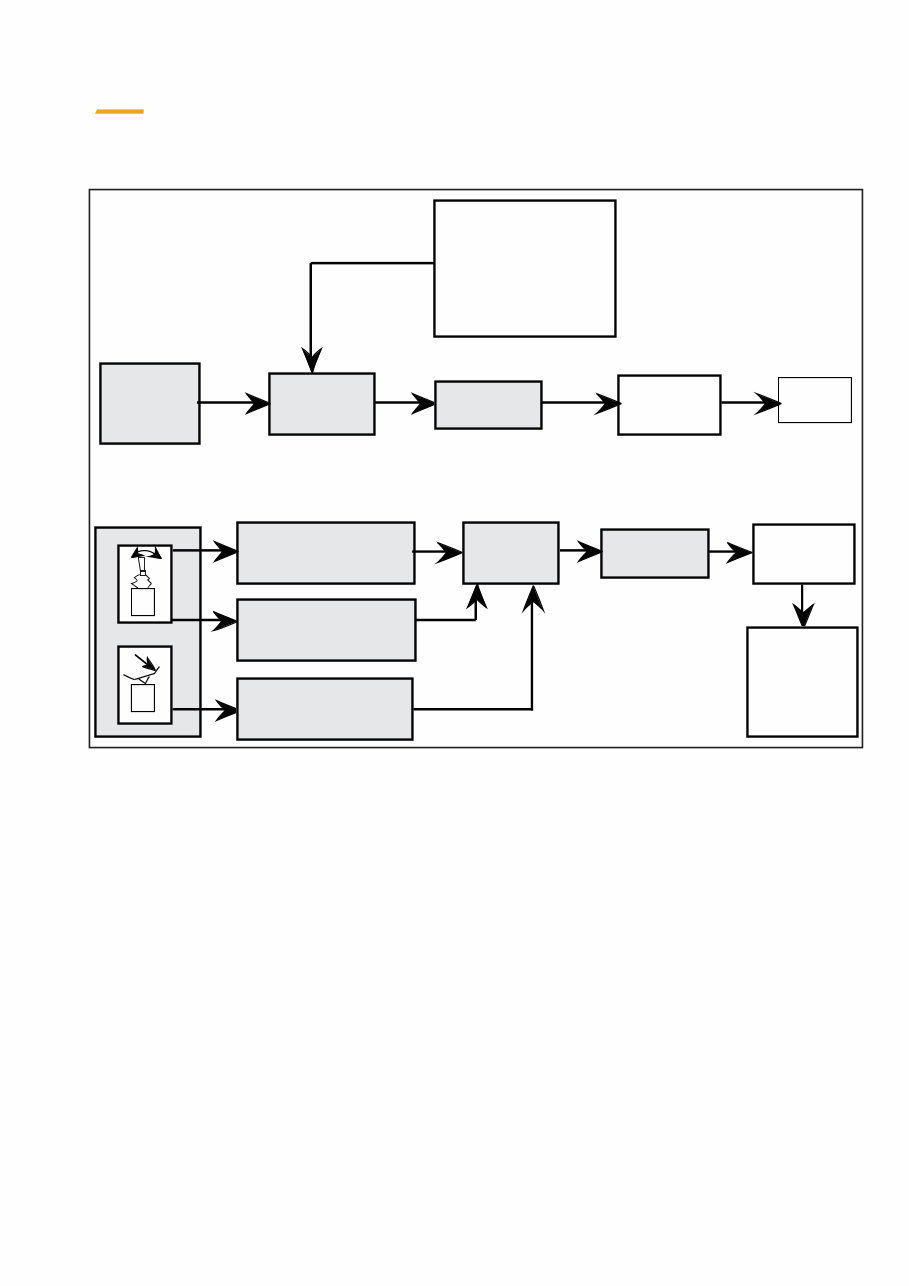
ELECTRIC ACCELERATION (AFTER ASSISTANCE WITH STARTING)
PURPOSE
To set the correct engine speed in accordance with the MODE selection made by the operator.
It provides the following :
• 2 idle modes
- LOW IDLE is the low idle speed at 950 rpm.
- High idle (1200 rpm) cannot be selected and is only obtained automatically during assistance with starting
when selecting AUTO-IDLE function (see page 1.5.00)
• 3 work modes
- FINE: 1600 rpm for low output work, and for handling
- ECO: 1850 (1288) or 1950 (1488) rpm, economical digging is possible
- MAX: 2240 rpm, maximum power, hard work
The mode is selected at the control box which informs the electronic control box. This sends a signal to the
servo-motor which is directly connected to the injection pump lever. In this way engine speed is obtained in
accordance with the selected mode.
1-5
CASE
Issued 11-97 Printed in England Mon 1288/1488 GB
Training Center
BASIC PRINCIPLES OF ELECTRONICALLY ASSISTED SYSTEMS
- Swing and travel
pressure switches not
actived
- Pressure sensor on
LS circuit with P
under 40 bar
t = 5 sec.
Electronic
control box
AUTO IDLE
on control
box
Servo motor
Injection
pump
1200
r.p.m.
Electronic
control
box
Servo-motor
Injection
pump
Engine speed
as per mode
selected
at beginning
Pressure sensor on LS
circuit with P
over 50 bar
- Swing pilot
pressure switche
- Travel pilot
pressure switche
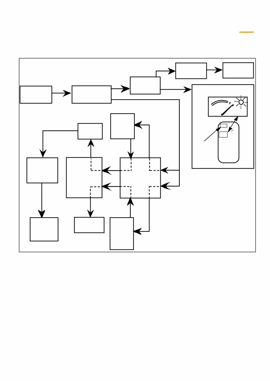
AUTOMATIC RETURN TO IDLE (AUTO-IDLE MODE)
PURPOSE
Sets engine speed to idle when none of the various controls for excavator functions are activated. This applies
whichever mode has been selected (FINE, ECO or MAX)
WORKING PRINCIPLES
- The indicator lamp on the push-button lights up when the AUTO-IDLE mode is pressed to obtain automatic
return to idle.
- On condition that no movement occurs at the control levers or pedals, also that the swing and travel pressure
switches show no action and that the LOAD SENSING information line is at a pressure lower than 40 bar, all this
for a period of 5 seconds.
- When these conditions are met, the electronic control box informs the injection pump servo-motor and the
AUTO-IDLE mode (idling at 1200 rpm) is obtained. The indicator lamp lights up on the push-button for the mode
selected.- When one or more of the controls is operated again, the engine returns to the speed of the mode
which was previously selected (FINE, ECO or MAX).
This is because information is given to the control box in the following manner:
For attachment and options functions
- When the L-S information pressure sensor detects a pressure greater than 50 bar
For the swing function
- When the pilot pressure switch receives a pressure information
For the travel function
- When the release pressure switch receives a pressure information
- In this case, the indicator lamp on the push-button stays on continuously.
Mon 1288/1488 GB Issued 11-97 Printed in England
1 -6
CASE
Training Center
BASIC PRINCIPLES OF ELECTRONICALLY ASSISTED SYSTEMS
FINE or
LOW
IDLE
MODES
MODES
MAXI
or
ECO
Buzzer
sounds
instrument
panel
Temp sensor
on engine
block
Water temp
over 115° C
Servo-moteur
Electronic
control
box
Push- button
to stop
the LED
ligts up
STOP
Indicator
lamp
lights up
110°
MODE
FINE
MODE
unchanged
Water temp
lower
100° C
Return to
selected
Mode
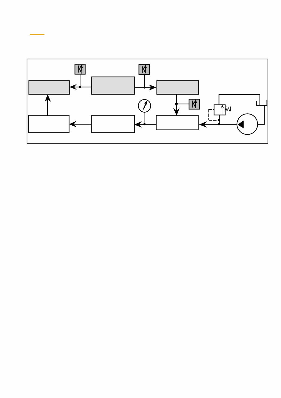
PURPOSE
Safeguards the engine as regards temperature
WORKING PRINCIPLES
- If the engine coolant solution reaches a temperature in excess of 115° C, the sensor on the engine block gives information to the
instrument panel
- The buzzer sounds (stopped by push-button)
- The stop warning lamp located at top left of instrument panel lights up.
- The engine temperature gauge needle is at the beginning of the 2nd red mark.
- The engine temperature gauge LED lights up.
- If the engine is in ECO or MAX, the information is transmitted to the electronic control box which reduces the engine speed to the FINE
mode and the “FINE” LED lights up.
- If the engine is in FINE or LOW IDLE, there is no change
- At 100° C, the various modes: FINE, ECO or MAX can again be selected.
ENGINE OVERHEATING SAFETY SYSTEM
1-7
CASE
Issued 11-97 Printed in England Mon 1288/1488 GB
Training Center
BASIC PRINCIPLES OF ELECTRONICALLY ASSISTED SYSTEMS
P 35
Proportional
valve
Pump power
(p x qv)
Torque regulator
valve
Engine speed
Sensor on engine
(flywheel teeth)
Electronic control
box
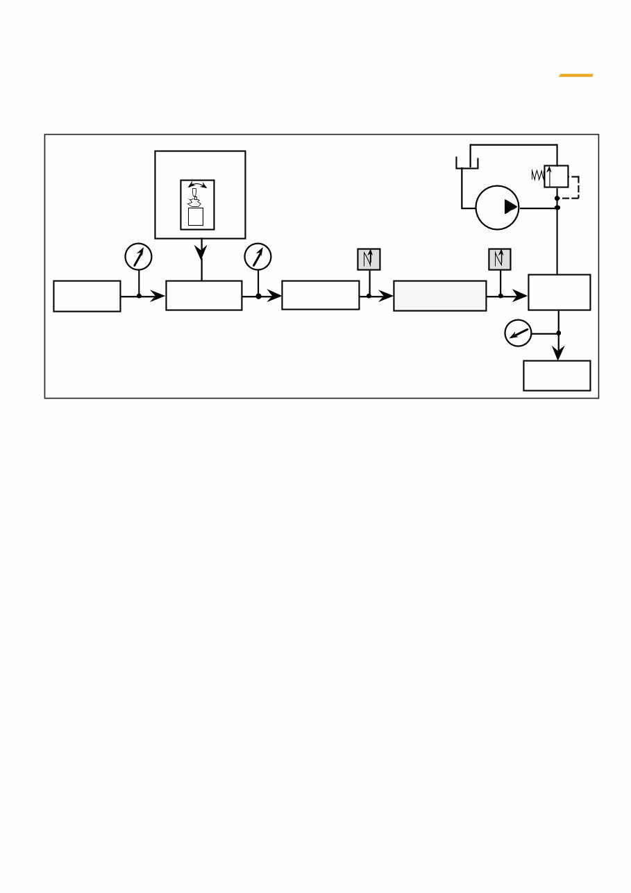
“SPEED-SENSING” SYSTEM
PURPOSE
It maintains power balance between the available engine power and the demands of the hydraulic system, regardless of engine speed
selected.
WORKING PRINCIPLES
- A sensor located on the teeth of the engine flywheel, detects engine speed and transmits it to the electronic control box.
- If the hydraulic power which has been consumed causes engine speed to fall, electric information coming from the electronic control
box acts on a hydraulic proportional valve, fed by pressure from the hydraulic assistance circuit.
- Depending on the intensity of the signal received, which depends itself on the engine speed, this valve delivers a pilot pressure which
acts on the torque regulator valve of the hydraulic pump, to reduce the flow supplied by the pump so that the hydraulic power consumed
is in line with engine speed (depending on mode selected)
Mon 1288/1488 GB Issued 11-97 Printed in England
1 -8
CASE
Training Center
BASIC PRINCIPLES OF ELECTRONICALLY ASSISTED SYSTEMS
P 35
Brake release
Electronic control
box
Control lever
Pressure
selector
Pressure switch
solenoid
valve
If counter- rotating
PURPOSE
- Enables the upperstructure swing hydraulic motor brake release to take place
WORKING PRINCIPLES
- When the control lever is tilted, the pilot pressure actuates a pressure selector. The pressure selector closes a pressure switch which
informs the electronic control box
- This in turn activates a solenoid valve, fed by the hydraulic assistance circuit pressure. This pressure arrives at the hydraulic motor
brake and releases the brake.
- Since the hydraulic motor is being fed it drives the upperstructure round by means of a reduction gear
- When the operator swings in the opposite direction, without stopping at the control lever neutral position, the pressure selector is
pressed onto the other side and the pressure switch informs the electronic control box, which maintains the swing brake in the released
position.
UPPERSTRUCTURE SWING BRAKE RELEASE
You're Reading a Preview
What's Included?
 Lifetime Access
Fast Download Speeds
Online & Offline Access
Access PDF Contents & Bookmarks
Full Search Facility
Print one or all pages of your manual
$71.99
CASE 1288 1288LC 1288CK 1488 Crawler Excavator SCHEMATIC Service Manual
Viewed 58 Times Today

What's Included?
Lifetime Access
Fast Download Speeds
Online & Offline Access
Access PDF Contents & Bookmarks
Full Search Facility
Print one or all pages of your manual
$71.99

Secure transaction
What's Included?
Lifetime Access
Fast Download Speeds
Online & Offline Access
Access PDF Contents & Bookmarks
Full Search Facility
Print one or all pages of your manual
Description
This is a comprehensive service manual for the CASE 1288, 1288LC, 1288CK, and 1488 Crawler Excavator models, covering a wide range of essential technical information for repair and maintenance.
- Serial numbers: ALL
- File Format: .PDF
- Pages: 222
- Size: 10Mb
- Manual Language: English
The manual includes detailed insights into the following key areas:
- BASIC PRINCIPLES OF ELECTRONICALLY ASSISTED SYSTEM
- ELECTRICAL SCHEMATICS
- BASIC PRINCIPLES OF THE HYDRAULIC CIRCUIT
- GENERAL HYDRAULICS
- HYDRAULIC PUMP
- LOAD SESING, TORQUE REGULATOR, FLOW CANCELLING AND INDEPENDENCE OF MOVEMENTS SYSTEM
- PILOT SYSTEM
- ATTACHMENT OPTION
- ATTACHMENT FUNCTION
- SWING FUNCTION
- TRAVEL FUNCTION
- PRESSURE SETTINGS
Whether you are a professional mechanic or a DIY enthusiast, this manual is an invaluable resource for your repair and maintenance needs. Feel free to reach out if you have any questions. We might just have the manual you've been searching for. Have a great day!


