9803/9320 Issue 1 Introduction This publication is designed for the benefit of JCB Distributor Service Engineers who are receiving, or have received, training by JCB Technical Training Department. These personnel should have a sound knowledge of workshop practice, safety procedures, and general techniques associated with the maintenance and repair of hydraulic earthmoving equipment. Renewal of oil seals, gaskets, etc., and any component showing obvious signs of wear or damage is expected as a matter of course. It is expected that components will be cleaned and lubricated where appropriate, and that any opened hose or pipe connections will be blanked to prevent excessive loss of hydraulic fluid and ingress of dirt. Finally, please remember above all else SAFETY MUST COME FIRST! The manual is compiled in sections, the first three are numbered and contain information as follows: 1 = General Information - includes machine operating procedures. 2 = Care & Safety - includes warnings and cautions pertinent to aspects of workshop procedures etc. 3 = Routine Maintenance - includes service schedules, procedures, torque settings and recommended lubricants. The remaining sections are alphabetically coded and deal with Dismantling, Overhaul etc. of specific components, for example: A = Attachments B = Body & Framework ...etc The page numbering in each alphabetically coded section is not continuous. This allows for the insertion of new items in later issues of the manual. Section contents, technical data, circuit descriptions, operation descriptions etc. are inserted at the beginning of each alphabetically coded section. All sections are listed on the front cover; tabbed divider cards align directly with individual sections on the front cover for rapid reference. Where a torque setting is given as a single figure it may be varied by plus or minus 3%. Torque figures indicated are for dry threads, hence for lubricated threads may be reduced by one third. ‘Left Hand’ and ‘Right Hand’ are as viewed from the rear of the machine facing forwards.
i i Section 1 Section 1 General Information 9803/9320 Issue 2* Contents Page No. Introduction 1 - 1 Walk Round Inspection 1 - 1 Identifying the Machine 1 - 2 Engine and Track Controls 2 - 1 Track Controls 2 - 2 Before starting the engine 2 - 3 Starting the engine 2 - 4 Stopping the engine 2 - 5 Refuelling the machine 3 - 1 Using Attachments and Site Safety 4 - 1 Working on slopes 4 - 2 Getting the machine moving 5 - 1 TD7/TD10 Operating the hydraulic dumper skip 6 - 1 Uninstalling the dumper skip 6 - 2 Installing the dumper skip 6 - 3 Shovel Loader 7 - 1 Installing the shovel loader 7 - 2 Connecting to the hydraulic system 7 - 3 Using the shovel loader 7 - 3 High Lift Shovel Loader 8 - 1 Using the high lift 8 - 1 Using the high lift warning device 8 - 1 Extending the undercarriage 8 - 2 Transporting the machine 9 - 1 Storage/Preparation 10 - 1 Troubleshooting 11 - 1 *
9803/9320 Issue 1 Section 1 Section 1 General Information 1 - 1 1 - 1 This chapter is arranged to guide you step-by-step through the task of learning how to use the machine. Read it through from beginning to end. By the end of the chapter you should have a good understanding of the machine and how to operate it. Pay particular attention to all safety messages. They are there to warn you of possible hazards. Do not just read them - think about what they mean. Understand the hazards and how to avoid them. If there is anything you do not understand, ask your JCB dealer, he will be pleased to advise you. When you have learned where the driving controls are and what they do, practise using them. Practise driving the machine in a safe, open space clear of other people. Get to know the "feel" of the machine and its driving controls. Move on to the attachment controls only when you can drive the machine confidently and safely. Take great care when practising with the attachment controls. Practise in an open space, keep people clear. Do not jerk the controls: operate them slowly until you understand the effect they have on the machine. Finally, do not rush the job of learning. Take your time and take it safely. Remember BE CAREFUL BE ALERT BE SAFE Introduction The following checks should be made each time you return to the machine after leaving it for any period of time. We advise you also to stop the machine occasionally during long work sessions and do the checks again. All these checks concern the serviceability of the machine. Some concern your safety. Get your service engineer to check and correct any defects. Machine Walk Round Inspection 1 Check for cleanliness: a Remove dirt and debris, especially from around the engine, skip rams and tracks. b Make sure the footplate and handrails are clean and dry. 2 Check for damage: a Inspect the machine generally for damaged and missing parts. b Check for oil and fuel leakages beneath the machine. ! WARNING You could be killed or injured with damaged tracks. Do not use the machine with damaged or excessively worn tracks. HOP27 3 Check the Tracks (Rubber) Check for cut rubber and penetration by sharp objects. Do not use a machine with damaged tracks. 4 Check the fuel filler cap Make sure the fuel filler cap is tightly closed. Walk Round Inspection
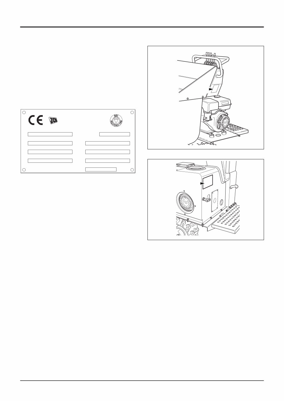
9803/9320 Issue 2* Section 1 Section 1 General Information 1 - 2 1 - 2 Identifying the Machine The machine has a Data Plate A attached to the left hand face of the machine, above the engine. On TD10 machines from serial no. 1011234 the Data Plate is fitted to the rear face of the engine cover, as shown at B. The serial numbers of the machine are stamped on this plate. The engine serial number is stamped on the engine. A J C BAMFORD EXCAVATORS LTD ROCESTER, STAFFS Product Identification Number VIN V ehicle Identification Number ENGINE SERIAL NUMBER WEIGHT kg LH TRACK GEARBOX SERIAL RH TRACK GEARBOX SERIAL ENGINE POWER kW @ RPM FM 14063 OSEN ISO9001 YEAR OF MANUFACTURE H04344 * T000100 B
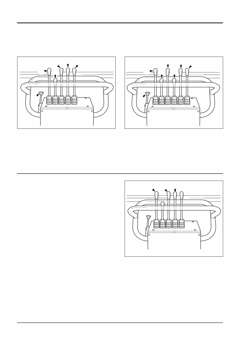
9803/9320 Issue 2* Section 1 Section 1 General Information 2 - 1 2 - 1 Engine and Track Controls 402271 D A C Track Controls The two tracks are controlled by a pair of control levers A and C. Each lever controls one track and is spring loaded to the central position. In this position the track does not operate. The left side lever controls the left track. The right side lever controls the right track. The two levers can be operated individually or together as necessary to move the machine as required. An increase in speed can be achieved by operating the two speed tracking lever D. Use this higher speed only on smooth level ground. ! WARNING Do not operate the controls from the side of the machine. When operating the machine, stand behind the controls at all times. Note: Illustration shows standard undercarriage controls. A Left track control lever B Skip control lever C Right track control lever D 2 speed control lever E Accessory hydraulic control lever F Remote throttle lever A Left track control lever B Skip control lever C Right track control lever D 2 speed control lever E Accessory hydraulic control lever F Remote throttle lever G Track extension Controls Standard undercarriage 402271 B A F D E C 768570 F A G B C D E Variable width undercarriage * * *
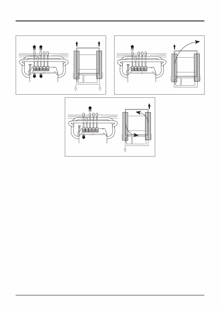
2 - 2 2 - 2 Issue 2* Section 1 Section 1 General Information 422422 422431 422441 A B C Engine and Track Controls - continued ! WARNING Do not operate the controls from the side of the machine, when operating the machine, stand behind the controls at all times. ! WARNING Make sure that all persons are clear before moving. ! WARNING Low speed must always be selected when unloading the machine from a vehicle or tracking down steep slopes. The machine will stop/start more abruptly when the levers are operated if high speed is selected. 0076 ! WARNING Ear Defenders In continuous 8-hour operation the average operator noise exposure from this machine can exceed 85 dB(A). In these circumstances ear plugs or noise defenders must be worn. If you do not wear ear plugs or noise defenders your hearing may be permanently damaged. The 8-hour averaged threshold of 85 dB(A) might not be reached if use of the machine is less than 8-hours and the noise exposure from other sources in the remaining period is less than 85 dB(A). An assessment of daily noise exposure should be undertaken to determine if hearing protection is required. Forward (A) To move the machine forward, push both levers forward. Release the levers to stop. The slower the track controls are moved to full travel, the more progressive the starting of the machine movement will be. Always stop the machine and drop the engine speed to idle before changing from forward to reverse or from reverse to forward. Reverse (A) To move the machine backward, pull both levers backward. Release the levers to stop. Turn (B) To turn the machine whilst travelling, move the lever back towards the central position on the side towards which you want to go e.g. move the left lever back to turn left. This causes the left track to move slower than the other. The faster moving right track will push the machine around. Spin (C) To spin the machine around through 360º, without moving it, operate one lever in a forward position and the other in a reverse position. This will cause the tracks to drive in opposite directions and hence push the machine around. It is recommended that low speed is selected when spin turning. 9803/9320 * *
9803/9320 Issue 2 Section 1 Section 1 General Information 2 - 3 2 - 3 Before starting the engine ! CAUTION Always carry out an inspection before starting the engine. This could prevent an accident or equipment damage. To prevent fire hazards and to provide adequate ventilation, the engine should be 1 metre away from buildings and other equipment. Do not place flammable items such as petrol, matches etc. close to the engine when it is running. Refuel in a well ventilated area with the engine stopped. Petrol is highly flammable and explosive under certain conditions. Do not overfill the fuel tank. There should be no fuel in the filler neck. Make sure the filler cap is tightly closed. Exhaust gases contain carbon monoxide. Avoid inhalation of exhaust gases. Never run the engine in a close, confined area. Engine and Track Controls - continued 403151 B A C
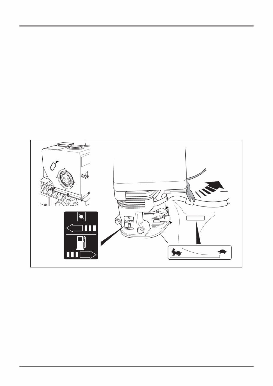
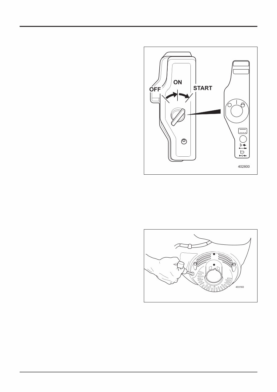
9803/9320 Issue 2* Section 1 Section 1 General Information 2 - 4 2 - 4 Engine and Track Controls - continued Engine Starting procedure - Electric start model 1 Turn the fuel valve A to the ON position. 2 Move the choke lever B to the CLOSED position. Note: It may not be necessary to use the choke if the engine is warm or the air temperature is high. Move the choke lever to a position to suit the prevailing conditions. 3 Open the remote throttle lever slightly. 4 Turn the ignition switch to the START position and hold until the engine starts. Note: Do not hold the ignition switch in the START position for more than 5 seconds. If the engine fails to start, release the switch and wait 10 seconds before operating the starter again. 5 When the engine starts, return the switch to the ON (middle) position. 6 As the engine warms up, gradually move the choke control to the fully OPEN position for normal working. Note: On TD10 machines from serial no. 1011234 access to the fuel valve and choke is through aperture C in the engine cover. Engine Starting procedure - Manual start model. 1 Turn the fuel valve A to the ON position. 2 Move the throttle lever B to the CLOSED position. Note: It may not be necessary to use the choke if the engine is warm or the air temperature is high. Move the choke lever to a position to suit the prevailing conditions. 3 Open the remote throttle slightly. 4 Pull the starter grip lightly until you feel resistance, then pull briskly. Return the starter grip gently. 5 As the engine warms up, gradually move the choke control to the fully OPEN position for normal working. *
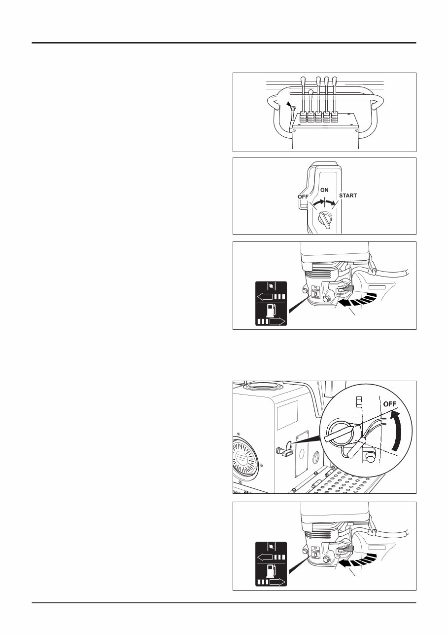
9803/9320 Issue 2 Section 1 Section 1 General Information 2 - 5 2 - 5 Stopping the engine Electric start model 1 Move the remote throttle lever A back to the idle position. 2 Turn the ignition switch to the OFF position. 3 Move the fuel valve to the OFF position. Emergency engine stop To stop the engine quickly, turn the ignition switch to OFF. Engine and Track Controls - continued Stopping the engine Manual start model 1 Move the remote throttle lever A back to the idle position. 2 Turn the switch to the OFF position. 3 Move the fuel valve to the OFF position. Emergence engine stop To stop the engine quickly, turn the fuel valve to OFF. 402271 A 402791 OFF OFF 402791 OFF OFF 417251
This is the COMPLETE official full factory service repair manual for the JCB TD7 TD10 Tracked Dumpster. Hundreds of pages allow you to print it out in its entirety or just the pages you need!! Its important to buy the right repair manual for your JCB TD7 TD10 Tracked Dumpster. It is great to have, will save you a lot and know more about your JCB TD7 TD10 Tracked Dumpster, in the long run.
This JCB TD7 TD10 Tracked Dumpster service manual is your number one source for repair and service information. They are specifically written for the do-it-yourselfer as well as the experienced mechanic. Using this JCB TD7 TD10 Tracked Dumpster repair manual is an inexpensive way to keep your vehicle working properly. JCB TD7 TD10 Tracked Dumpster service manual provides step-by-step instructions based on the complete disassembly of the machine. It is this level of detail, along with hundreds of photos and illustrations, that guide the reader through each service and repair procedure.
JCB TD7 TD10 Tracked Dumpster Workshop Service Repair Manual Includes the following aspects:
JCB TD7 TD10 Tracked Dumpster General Information
JCB TD7 TD10 Tracked Dumpster Care and Safety
JCB TD7 TD10 Tracked Dumpster Routine Maintenance
JCB TD7 TD10 Tracked Dumpster Attachments
JCB TD7 TD10 Tracked Dumpster Body and Framework
JCB TD7 TD10 Tracked Dumpster Electrics
JCB TD7 TD10 Tracked Dumpster Controls
JCB TD7 TD10 Tracked Dumpster Hydraulics
JCB TD7 TD10 Tracked Dumpster Gearboxes
JCB TD7 TD10 Tracked Dumpster Track and Running Gear
JCB TD7 TD10 Tracked Dumpster Engine
And MORE !!
Simply print out the pages you need or print the entire manual as a whole!!!
Detailed substeps expand on repair procedure information
Notes, cautions and warnings throughout each chapter pinpoint critical information
Numbered instructions guide you through every repair procedure step by step
Bold figure number help you quickly match illustrations with instructions
Detailed illustrations, drawings and photos guide you through every procedure
Enlarged inset helps you identify and examine parts in detail
Numbered table of contents easy to use so that you can find the information you need fast
This JCB TD7 TD10 Tracked Dumpster service manual also makes it easy to diagnose and repair problems with your machine's electrical system. Troubleshooting and electrical service procedures are combined with detailed wiring diagrams for ease of use.
GET YOUR JCB TD7 TD10 Tracked Dumpster SERVICE MANUAL NOW!
Complete comes in format which can work under all PC based windows operating system and Mac also. It saves to your hard-drive and can be burned to CD-ROM. All pages are printable. No need to pay for shipping and wait for the overpriced paper textbook or CD-ROM to arrive via snail mail. IT NOW!!
PRODUCT DETAILS:
File Format:
Language: English
Printable: without any restriction
Delivery: link will appear on the checkout page after payment is complete
Requirements: Adobe Reader
Recently Viewed
5,521,897Happy Clients
2,594,462eManuals
1,120,453Trusted Sellers
15Years in Business
Price:
Actual Price:
JCB TD7 TD10 Tracked Dumpster Workshop Service Repair Manual