


Issue no. 3
Part no. T0423
© Thwaites Limited
Service
Manual
Mach 202 – 1 Tonne Powerswivel Mach 201 – 1 Tonne Hi-tip
1 Tonne
1 Tonne
D
C
F
E
A
B
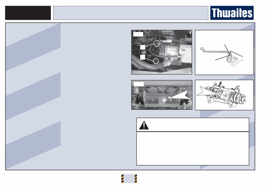
Towing the vehicle
In order to tow the vehicle, the hydrostatic drive on the engine
must be bypassed, and the spring-applied brakes at the two rear
wheel motors must be disconnected.
Bypassing the hydrostatic drive
This is achieved by unscrewing two valves on the pump. One
valve is beneath the footplate (Fig. 1 (A)); the other is opposite
this, underneath the pump (Fig. 1 (B)).
To activate the hydrostatic transmission bypass:
• release lock nut (Fig. 2(C));
• screw in grub screw (Fig. 2(D))) until flush with top of nut (C);
• tighten nut (D).
To re-activate the hydrostatic transmission:
• screw back item D to stop;
• screw back the nut and tighten.
Disconnect the spring-loaded brakes
• Dismantle the two extractors (Fig. 3 (E))) attached at the rear
axle box (This is achieved by unscrewing the hexagon bolts)
• remove the plastic plug in the centre of the wheel motor face.
• place the extractor on the wheel motor (Fig. 4 (F))) and screw
in the hexagon bolt removed earlier.
• Tighten bolt to 42 Nm until wheel removes freely.
• Replace extractors to re-activate spring-loaded brakes.
CAUTION
Chock the wheels when the brakes are disconnected.
When towing the vehicle:
• Do not exceed the maximum towing speed of 2 km/h.
• Do not exceed the towing distance of 1 km.
• Under no circumstances drive the vehicle with the
brakes disconnected.
TOWING RECOVERY
Fig. 1 Fig. 2
Fig. 4 Fig. 3
1 Tonne
This manual has been written to provide maintenance and
service information necessary to keep the Thwaites machine
operating safely and efficiently throughout its service life.
Prior to Commencing Maintenance Work You Must :
• Read and fully understand the enclosed working instructions.
• Ensure that any required safety precautions have been taken.
• Adhere to safety notices contained within this manual.
• Fully understand the risks involved and be competent to
perform the work.
• Use only genuine spare parts as replacement items.
• Ensure that prior to the machine being used, after
maintenance work has been completed, all safety checks and
tests have been completed.
Any problems please contact your local distributor
In compiling this document we have endeavoured to provide
the most up to date and accurate information.
Due to Thwaites continual product development we reserve the
right to amend information contained within this manual without
prior notice.
INTRODUCTION

1 Tonne
Technical Data ................................................................. 1
Maintenance/Towing Recovery ...................................... 2
CONTENTS

1 Tonne
1.0
Machine Identification .................................................. 1.1
Location of Major Components (Hi-tip) ....................... 1.2
Location of Major Components (Powerswivel) ........... 1.3
Torque Settings/Capacities .......................................... 1.4
SECTION 1 - TECHNICAL DATA
1 Tonne
1.1
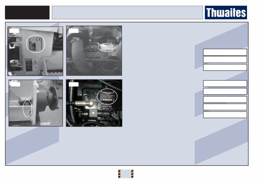
Serial Numbers
Note the vehicle’s serial numbers. Always quote them in
communication with your Thwaites dealer or Head Office.
Model Type (Fig 1.)
Vin Nº (Fig. 1)
Engine Serial Nº (Fig. 2)
Drive Motor Serial Nº (Fig. 3):
F (LH)
F (RH)
R (LH)
R (RH)
Drive Pump Nº (Fig. 4)
MACHINE IDENTIFICATION
Fig. 1 Fig. 2
Fig. 4 Fig. 3
1 Tonne
1.2
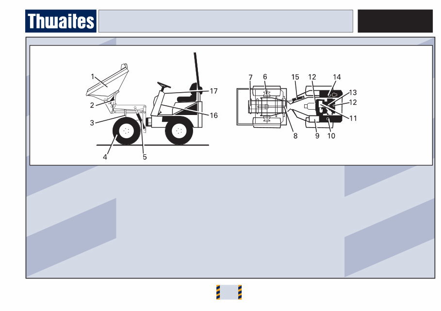
1 Skip
2 Skip prop
3 Arm prop
4 Wheel
5 Lift arm rams
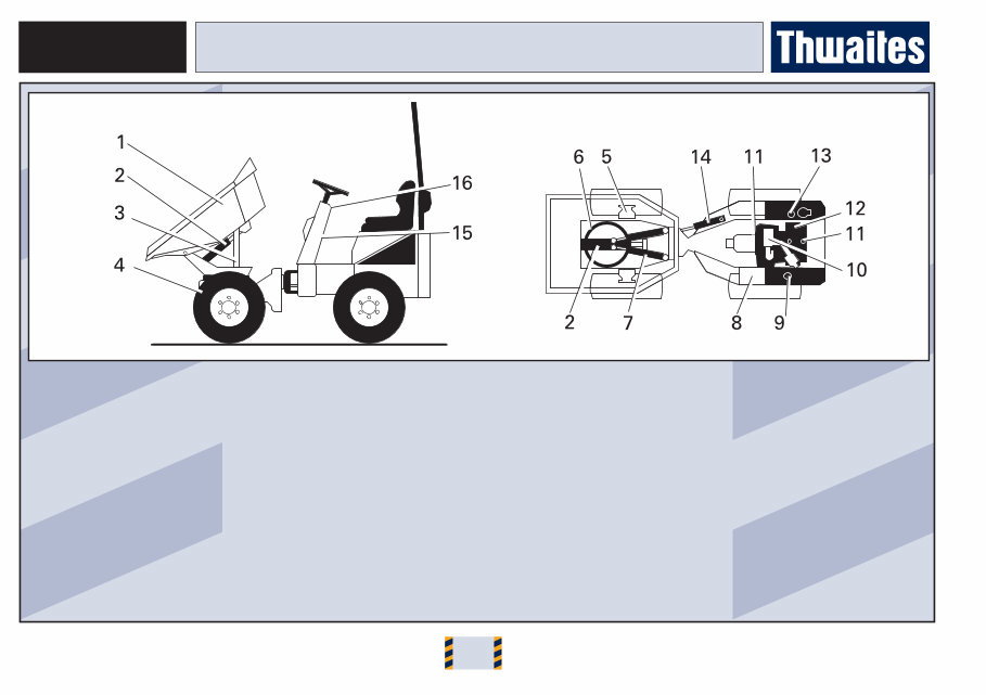
LOCATION OF MAJOR COMPONENTS – HI-TIP
6 Wheel motors (x4)
7 Tipping ram
8 Chassis pivot
9 Battery box
10 Fuel tank
11 Air filter
12 Radiator/oil cooler
13 Engine
14 Hydraulic tank
15 Steering ram
16 Operator manual housing
17 Steering unit
1 Tonne
1.3
1 Skip
2 Tipping ram
3 Safety prop
4 Wheel
LOCATION OF MAJOR COMPONENTS - POWERSWIVEL
5 Wheel motors (x4)
6 Slew ring
7 Slew ram
8 Battery box
9 Fuel tank
10 Air cleaner
11 Radiator/Oil cooler
12 Engine
13 Hydraulic tank
14 Steering ram
15 Operator manual housing
16 Steering unit

1 Tonne
1.4
System Fluid Capacities Ltrs
Engine oil (with filter) ............................................................... 4.1
Cooling system ...................................................................... 11.0
Hydraulic system ................................................................... 20.0
Fuel tank ................................................................................. 20.0
Torque Settings Nm
Wheel Nuts .............................................................................. 170
Engine Bracket/Rubber Mounts ................................................ 75
Engine Brackets/Engine Mounts ............................................... 56
Diesel/Hydraulic Tank Drain Plugs ............................................ 25
Mounting bolts for wheel motor assembly ............................ 134
Pump mounting ......................................................................... 80
Centre pivot nut (page 2.19)
Centre pivot pins ..................................................................... 200
SECTION 1 - TECHNICAL DATA
1 Tonne
You're Reading a Preview
What's Included?
Fast Download Speeds
Online & Offline Access
Access PDF Contents & Bookmarks
Full Search Facility
Print one or all pages of your manual
$36.99
Thwaites 202 1 Tonne dumper parts manual
Viewed 68 Times Today

What's Included?
Fast Download Speeds
Online & Offline Access
Access PDF Contents & Bookmarks
Full Search Facility
Print one or all pages of your manual
$36.99

Secure transaction
What's Included?
Fast Download Speeds
Online & Offline Access
Access PDF Contents & Bookmarks
Full Search Facility
Print one or all pages of your manual
Description
Get access to the official parts manual for the Thwaites 202 1 Tonne dumper. This manual provides detailed exploded views and parts lists for every component of the dumper. Whether you're a professional mechanic or a DIY enthusiast, this manual makes it easy to identify the exact part you need before ordering and replacing it.


