

Models
Muck-Truck Mk IV Dumper
MAX Mk II Dumper
Starting with Serial Number 101
Muck-Truck Mk IV Dumper
MAX Mk II Dumper
03737210 12/08
Printed in USA
Owner, Operation, Accessories & Parts Manual
ENGLISH

GB – 2
ASSEMBLY. . . . . . . . . . . . . . . . . . . . . . . . . . . . . . . . . 3
SAFETY . . . . . . . . . . . . . . . . . . . . . . . . . . . . . . . . . . . 4
CONTROLS AND FEATURES . . . . . . . . . . . . . . . . . . 5
OPERATION . . . . . . . . . . . . . . . . . . . . . . . . . . . . . . . . 6
MAINTENANCE . . . . . . . . . . . . . . . . . . . . . . . . . . . . . 8
SERVICE AND ADJUSTMENTS. . . . . . . . . . . . . . . . . 9
PARTS LIST . . . . . . . . . . . . . . . . . . . . . . . . . . . . . . . 12
ACCESSORIES . . . . . . . . . . . . . . . . . . . . . . . . . . . . . 18
WARRANTY . . . . . . . . . . . . . . . . . . . . . . . . . . . . . . . 28
THE MANUAL
Before using the unit, carefully and completely read your
manual. The contents will give you an understanding of
safety instructions and controls during normal operation
and maintenance.
All reference to left, right, front, or rear are given from the
operator’s position, facing the direction of forward travel.
ENGINE MANUAL
The engine on this unit is covered by a separate manual
specific to the engine. This manual is included in the
literature package that shipped with the unit. Refer to this
manual for engine service recommendations. If the
engine manual is not available, contact the engine
manufacturer for a replacement manual.
PURCHASE INFORMATION
Please record the following information about your unit
and have it available before contacting us.
Serial Number:
Dealer/Distributor’s Name:
Date of Purchase:
Year of Manufacture:
The undersigned of Niche Product Sales LLC declare that the Pedestrian Dumper Trucks:
Category: Gasoline 4-Stroke Pedestrian Dumper
Model: Muck-Truck Mk IV Dumper / MAX Mk II Dumper
Conform with the essential Health and Safety requirements of the EEC Directive.
98/37/EC (Edition L 207)
Previously 89/392/EEC – 93/94/EEC Amendment
Basic Noise Emission Standard – EN ISO 3744 – dB 97 Lwa
H.A.V.s
Machinery Directive 89/392/EEC
The supply of (Safety) regulations 1992 (as amended: 1994), for conformity in an EU market
Specified testing unit to: ISO 8041, ISO 5349 and BS 6842
Place: 586 Mercantile Place
Port St. Lucie, Florida 34986 USA
Name and signature of Technical Manager of Niche Product Sales LLC.
Terry Rowlands
TABLE OF CONTENTS
INTRODUCTION
DECLARATION OF CONFORMITY
Left Hand
Idle : 2.79 m/s
2
Right Hand
Idle : 3.10 m/s
2
Racing : 4.95 m/s
2
Racing : 5.86 m/s
2
© Copyright 2008 Niche Product Sales LLC
GB – 3
Remove From Crate
1. Remove crate top and sides.
2. Remove protective plastic covering.
3. Remove 5/16 x 2" hex bolts from Manual Package.
4. Cut and remove four plastic shipping bands from
axles.
Unit can remain on crate base during handle installation.
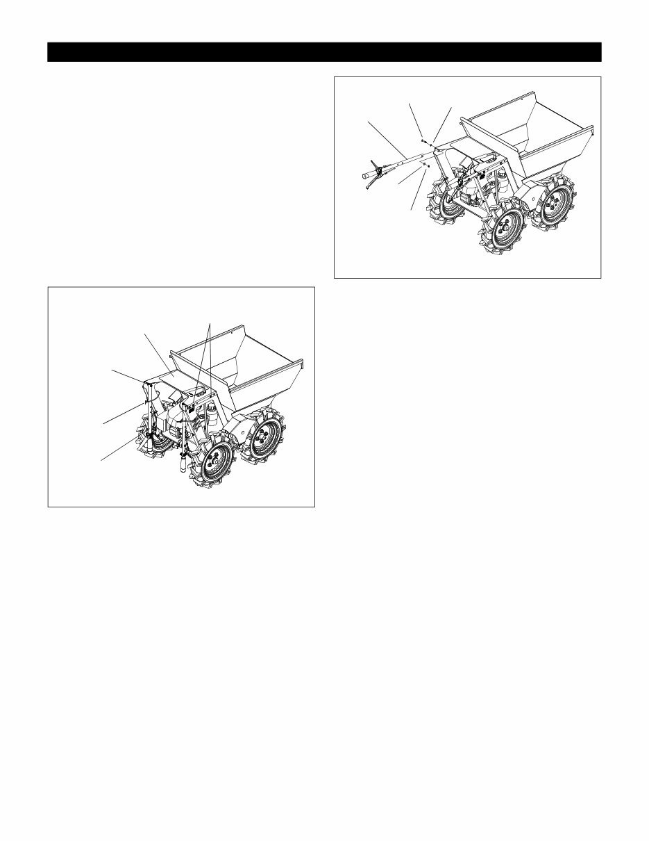
Install Handles
Handles are shipped in downward position (see Figure 1)
with all levers and cables correctly positioned.
NOTE: MAX Mk II handles can be mounted in two
positions depending on the desired handle length.
Ensure that both sides are mounted at the same length.
Muck-Truck Mk IV handles have one mounting location.
NOTE: Install handles one side at a time.
Figure 1
1. Cut tie-straps retaining handles.
2. Remove two 5/16 x 2" hex bolts, nuts and washers
securing one side of cowling cover plate. Retain all
hardware.
3. Remove 5/16 x 3" shipping hex bolt securing
handle to unit. Retain nut and washers; discard 3"
hex bolt.
Figure 2
4. Align handle with the holes in the cowling cover and
attach with two 5/16 x 2" bolts, washers and 5/16"
lock nuts removed earlier.
5. Insert 5/16 x 2" hex bolt from Manual Package into
remaining hole and secure with washers and nut
removed from shipping bolt.
6. Tighten hardware securely.
7. Repeat steps 2 – 6 for remaining side.
IMPORTANT: Ensure that MAX Mk II handles are
mounted at the same length.
8. Remove unit from crate base.
ASSEMBLY
Figure 1
Tie Strap
3" Shipping
Bolt
Handle
Cowling
Mounting Bolts Cowling
Cover Plate
Figure 2
Handle
5/16 x 2"
Hex Bolt
5/16 Hex
Nut
Flat Waher
Flat
Washer
GB – 4
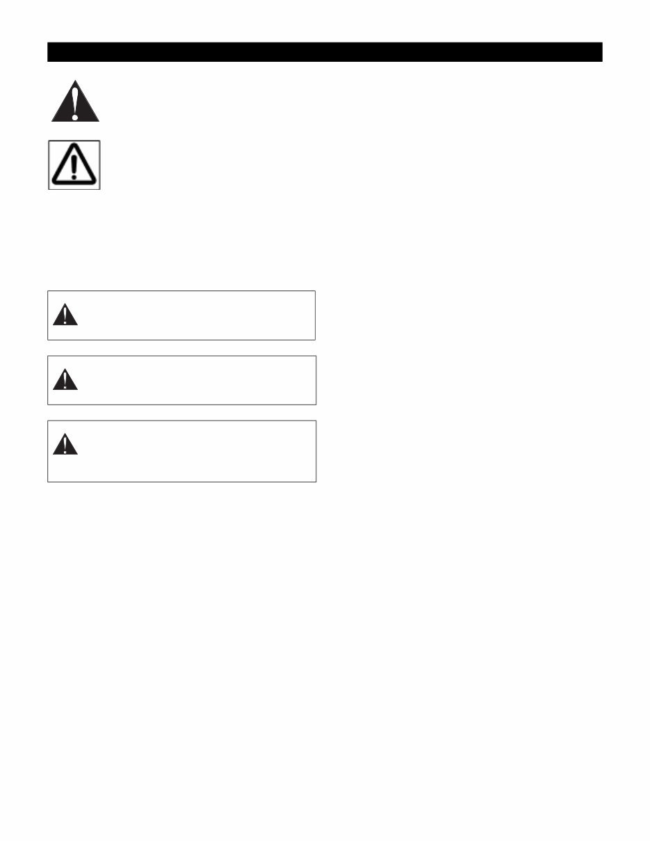
SAFETY ALERT SYMBOL
These are safety alert symbols. They
mean:
•ATTENTION!
•YOUR SAFETY IS INVOLVED!
When you see this symbol:
•BECOME ALERT!
•OBEY THE MESSAGE!
SIGNAL WORDS
The safety alert symbols above and signal words below
are used in this manual.
Read and understand all safety messages.
SAFETY RULES
Read, understand, and follow all safety practices in
Owner/Operator Manual before use. Failure to follow
instructions could result in personal injury and/or damage
to unit.
Complete a walk around inspection of unit and work area
to understand:
• Work area • Your unit • All operational decals
Inspect unit before each use for: missing or damaged
decals and shields. Replace or repair as needed.
Keep children out of work area and under watchful care
of a responsible adult.
Check for weak spots on docks, ramps or floors. Avoid
uneven work areas and rough terrain. Stay alert for
hidden hazards or traffic.
DO NOT operate near drop-offs, ditches, or
embankments. Unit can suddenly turn over if wheels
move over the edge of a cliff or ditch, or if an edge caves
in.
Read the entire Owner/Operator manual. If the operator
or the mechanic cannot read the manual, it is the owner’s
responsibility to explain it to them. Only the user can
prevent and is responsible for accidents or injuries
occurring to themselves, other people or property.
Only trained adults may operate or service unit. Training
includes actual operation.
NEVER operate unit after or during the use of
medication, drugs or alcohol. Safe operation requires
your complete and unimpaired attention at all times.
Wear adequate safety gear, protective gloves and
footwear.
NEVER place your hands or any part of your body or
clothing inside or near any moving part while unit is
running.
DO NOT touch parts which are hot. Allow parts to cool.
ALWAYS keep hands and feet away from all pinch
points.
Read, understand, and follow all instructions in the
manual and on the machine before starting.
Understand:
• How to operate all controls
• The functions of all controls
• How to STOP in an Emergency
• Braking and turning characteristics
Keep safety devices or guards in place and functioning
properly. NEVER modify or remove safety devices.
Never carry passengers.
Use only attachments and accessories designed for your
unit.
Know the weight of loads. Do not exceed maximum
capacity of unit.
Use caution when backing up. ALWAYS back up slowly.
Always look down and behind before and while backing.
Check all hardware at regular intervals. Keep all nuts,
bolts, and wheel lug nuts properly tightened.
Disengage unit drive by releasing clutch lever before
changing gears.
Never leave a running unit unattended. ALWAYS shut off
engine before leaving unit.
This product is equipped with an internal combustion
type engine. DO NOT use unit on or near any
unimproved, forest-covered or brush covered land unless
exhaust system is equipped with a spark arrester
meeting applicable local, state or federal laws. A spark
arrester, if used, must be maintained in effective working
order.
Fumes from engine exhaust can cause injury or death.
Ensure proper ventilation. Do not run engine in a
confined area.
Keep engine and exhaust clean and free of accumulated dirt, grease, oil of other flammable material.
SAFETY
DANGER: IMMINENTLY HAZARDOUS
SITUATION! If not avoided, WILL RESULT in
death or serious injury.
WARNING: POTENTIALLY HAZARDOUS
SITUATION! If not avoided, COULD RESULT
in death or serious injury.
CAUTION: POTENTIALLY HAZARDOUS
SITUATION! If not avoided, MAY RESULT in
minor or moderate injury. It may also be used
to alert against unsafe practices.
OL1253
OL3900
GB – 5
Do not use a pressure washer directly on engine
electronics.
Fuel is highly flammable and its vapors are explosive.
Handle with care. Use an approved fuel container.
NO smoking, NO sparks, NO flames. NEVER fill fuel tank
when engine is running or hot from operation, or if an
open flame or cigarette is present.
NEVER fill or drain fuel tank indoors.
Replace fuel cap securely and clean up spilled fuel.
Never fill containers inside a vehicle or on a truck or
trailer bed with a plastic liner. Always place containers on
the ground away from vehicle before filling.
Keep fuel nozzle in contact with the rim of the fuel tank or
container opening at all times until fueling is complete.
Do not use a nozzle lock-open device.
If fuel is spilled on clothing, change clothing immediately.
DO NOT change engine governor settings or over-speed
engine.
A damaged or worn out muffler can cause fire or
explosion. Replace with manufacturer-recommend parts.
NEVER store unit with fuel in fuel tank, inside a building
where any ignition sources are present such as hot water
heaters, space heaters, or clothes dryers. Allow the
engine to cool before storing in any enclosure.
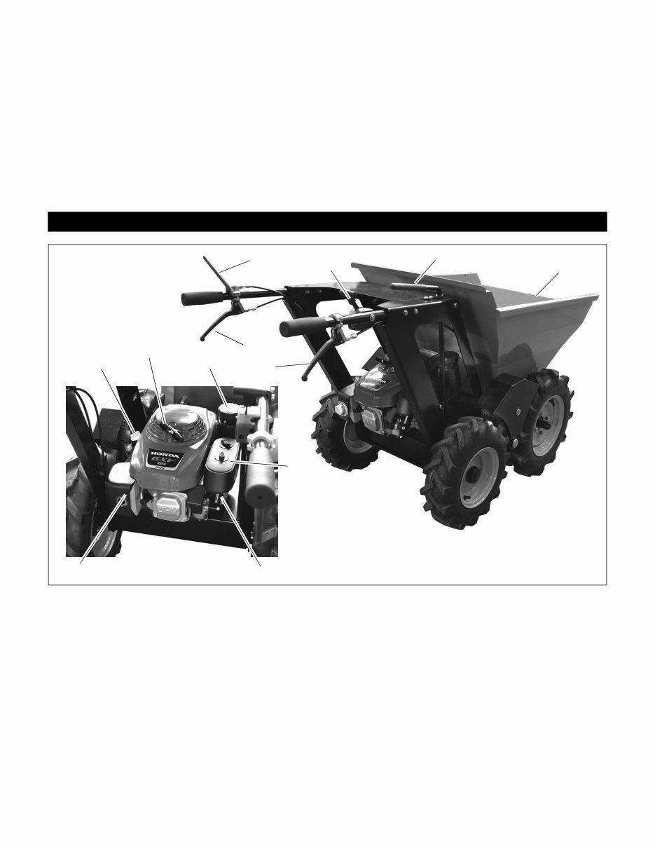
1. Parking Brake Lever
2. Throttle Lever
3. Gear Selection Lever
4. Clutch Lever
5. Skip Release Lever
6. Skip
7. Oil Level Dipstick/Fill
8. Recoil Starter Handle
9. Fuel Tank/Cap
10. Air Cleaner
11. Fuel Shut-off Valve
12. Muffler
CONTROLS AND FEATURES
Figure 3
1 2
4
5
6
8
9
3
7
10
11 12
GB – 6
CONTROLS AND FEATURES
See CONTROLS AND FEATURES on page 5.
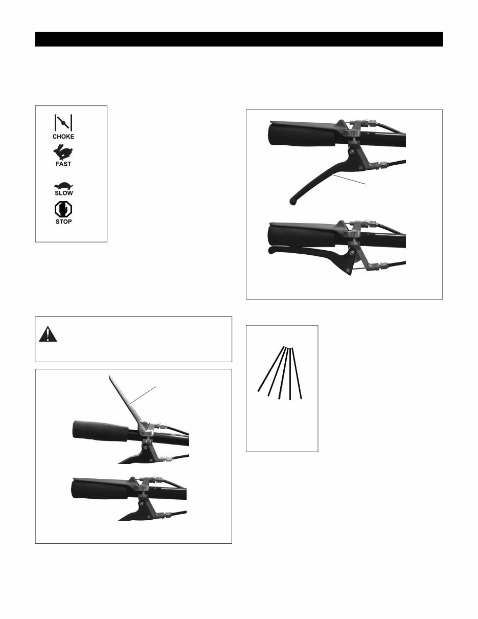
Throttle Lever
(Figure 4)
The throttle lever controls the
choke position and the engine
speed. To choke the engine for
startup adjust to:
1. CHOKE (startup)
To increase or decrease the
engine speed, adjust to:
2. FAST
3. Part-Throttle
4. SLOW
To stop the engine, adjust to
5. STOP (engine is off)
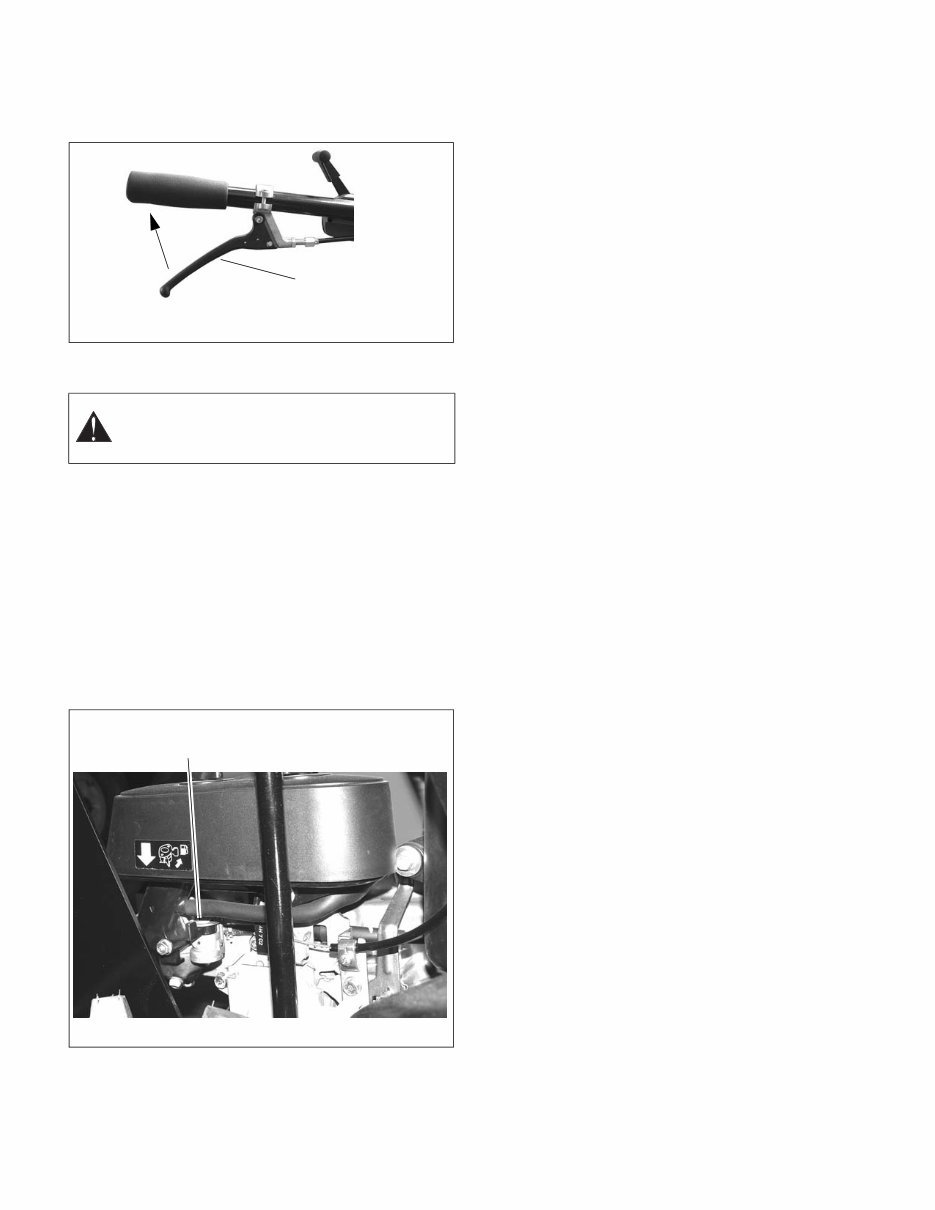
Parking Brake Lever
(Figure 5)
Engage the parking brake by releasing the lever when
not traveling with the unit or while emptying the skip. The
parking brake lever must be disengaged (pressed down
against handlebar) any time that the unit is in motion.
Clutch Lever
(Figure 6)
With a forward or reverse gear selected, gently engage
(squeeze) the clutch lever to move the unit forward or
backward. Release the clutch lever to stop motion.
Gear Selection Lever
(Figure 7)
The gear selection lever controls
forward and reverse motion of the
unit and adjusts the forward travel
speed. Select the desired gear
based on travel conditions:
OPERATION
CAUTION: Avoid damage. Unit has sufficient
power to overpower the parking brake. Not
releasing parking brake while traveling will lead
to overheating and premature wear.
1
2
3
4
5
Figure 4
Figure 5
Parking Brake
Off
Parking Brake On
Parking Brake
Lever
3 Fast Forward
2 Medium Forward
1 Slow Forward
N Neutral (no gear selected)
R Reverse
Clutch
Disengaged
Clutch Lever
Clutch Engaged
Figure 6
N
R 1
2
3
Figure 7
GB – 7
Skip Release Lever
(Figure 8)
Squeeze the skip release lever to release the skip lock.
Release the skip release lever to engage the skip lock.
PRE-START
Park unit on level surface. Check and add fuel if required.
Check that the engine crankcase oil is full using dipstick.
Refer to Engine Manual for detailed instructions.
Fuel Shut-Off Valve
NOTE: Close the fuel shut-off valve before transporting
the unit.
The fuel shut-off valve has two positions:
• Closed Position – Use this position to service,
transport, or store the unit.
• Open Position – Use this position to operate the
unit.
Adding Fuel
1. ALWAYS place unit in open or well-ventilated area.
2. Stop engine and allow to cool.
3. Remove accessory or tilt forward to gain access to
fuel tank.
4. Clean fuel cap and surrounding area to prevent dirt
from entering fuel tank.
5. Remove cap.
NOTE: DO NOT add oil to fuel. DO NOT use gasohol or
gasoline containing alcohol. See Engine Manual for
correct type and grade of fuel.
6. Fill fuel tank to within 1/2 in. (1.2 cm) of bottom of
filler neck with unleaded gasoline.
7. Replace fuel cap and tighten.
8. ALWAYS clean up any spilled fuel.
STARTING UNIT
1. Move the throttle lever into the Choke position by
moving it fully forward.
NOTE: A warm engine requires less choking than a cold
engine.
2. Grasp recoil starter handle and pull rope out slowly
until it engages.
3. Pull rope with a rapid continuous full arm stroke. Let
rope rewind slowly.
NOTE: DO NOT let starter handle snap back against
engine.
4. Repeat steps 2 and 3 until engine starts.
5. Move throttle lever to the rear to disengage the
choke and set engine speed to idle.
6. Allow engine to warm.
7. Set throttle to desired position based on travel
conditions and gear selected.
OPERATION
To Move Forward
1. Select desired speed (1, 2 or 3) with gear selection
lever.
2. Press parking brake lever down to handlebar.
3. Gently engage clutch lever.
To Move In Reverse
1. Stop forward travel of unit.
2. Move gear selection lever to reverse (R) position.
3. Press parking brake lever down to handlebar.
4. Check behind for obstacles and ensure that travel
path is clear.
5. Gently engage clutch lever.
To Stop Unit
1. Release clutch lever.
2. Release parking brake lever.
3. Reduce engine speed with the throttle control lever.
WARNING: AVOID INJURY. Read and
understand the entire Safety section before
proceeding.
Figure 8
Skip Release
Lever
Squeeze
lever to
release
skip lock
Figure 9
Fuel shut-off valve (Shown
in Closed position)
GB – 8
To Empty Skip
1. Stop unit and release parking brake lever.
2. Release the skip lock by squeezing the skip release
lever.
3. Jerk both handlebar handles upwards. The skip will
pivot forward and dump the load.
To Reset Skip
1. Pull back on the skip.
2. Engage the skip lock by releasing the skip lock
lever.
3. Ensure that skip lock has engaged before moving
unit.
MAINTENANCE CHECK LIST
Perform routine checks as outlined below. Correct any
problems before using unit.
* SAE 10W-30 oil is recommended for general use. Refer
to engine manual for engine maintenance procedures.
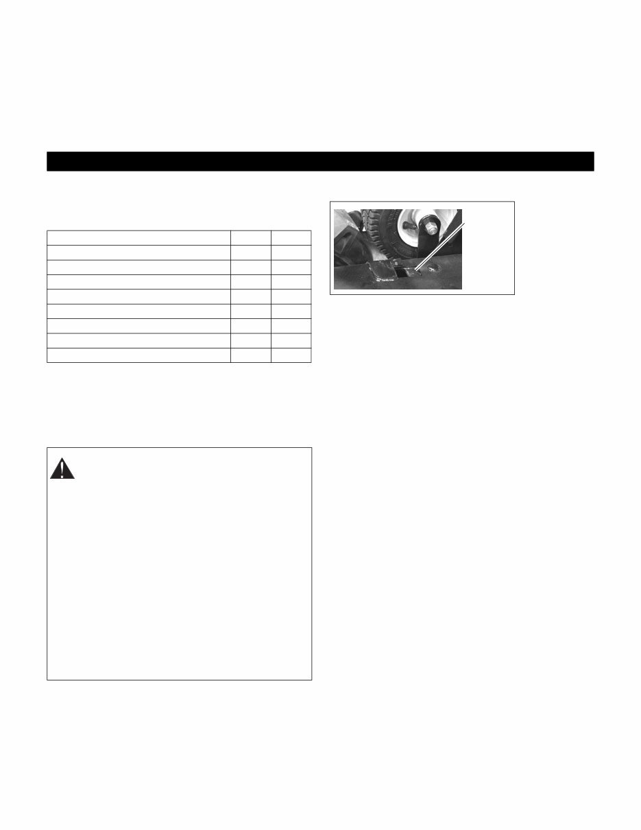
Tire Pressure
1. Check tire air pressures regularly. Recommended
inflation pressure is 30 psi for all tires.
LUBRICATION
Apply spray
lubricant to skip
release as
necessary. DO
NOT use oil or
grease.
MAINTENANCE
Component Daily Weekly
Skip Lock Spring X
Drive Belt Tension X
Parking Brake Adjustment X
Control Cable Condition and Adjustment X
Air Cleaner X
Engine Oil Level * X
Tire Pressures X
Attaching Hardware X
CAUTION: Avoid injury! Explosive separation of
tire and rim parts is possible when they are
serviced incorrectly:
• Do not attempt to mount a tire without the
proper equipment and experience to
perform the job.
• Do not inflate the tires above the
recommended pressure.
• Do not weld or heat a wheel and tire
assembly. Heat can cause an increase in
air pressure resulting in an explosion.
Welding can structurally weaken or deform
the wheel.
• Do not stand in front or over the tire
assembly when inflating. Use a clip-on
chuck and extension hose long enough to
allow you to stand to one side.
Apply
spray
lubricant.
GB – 9
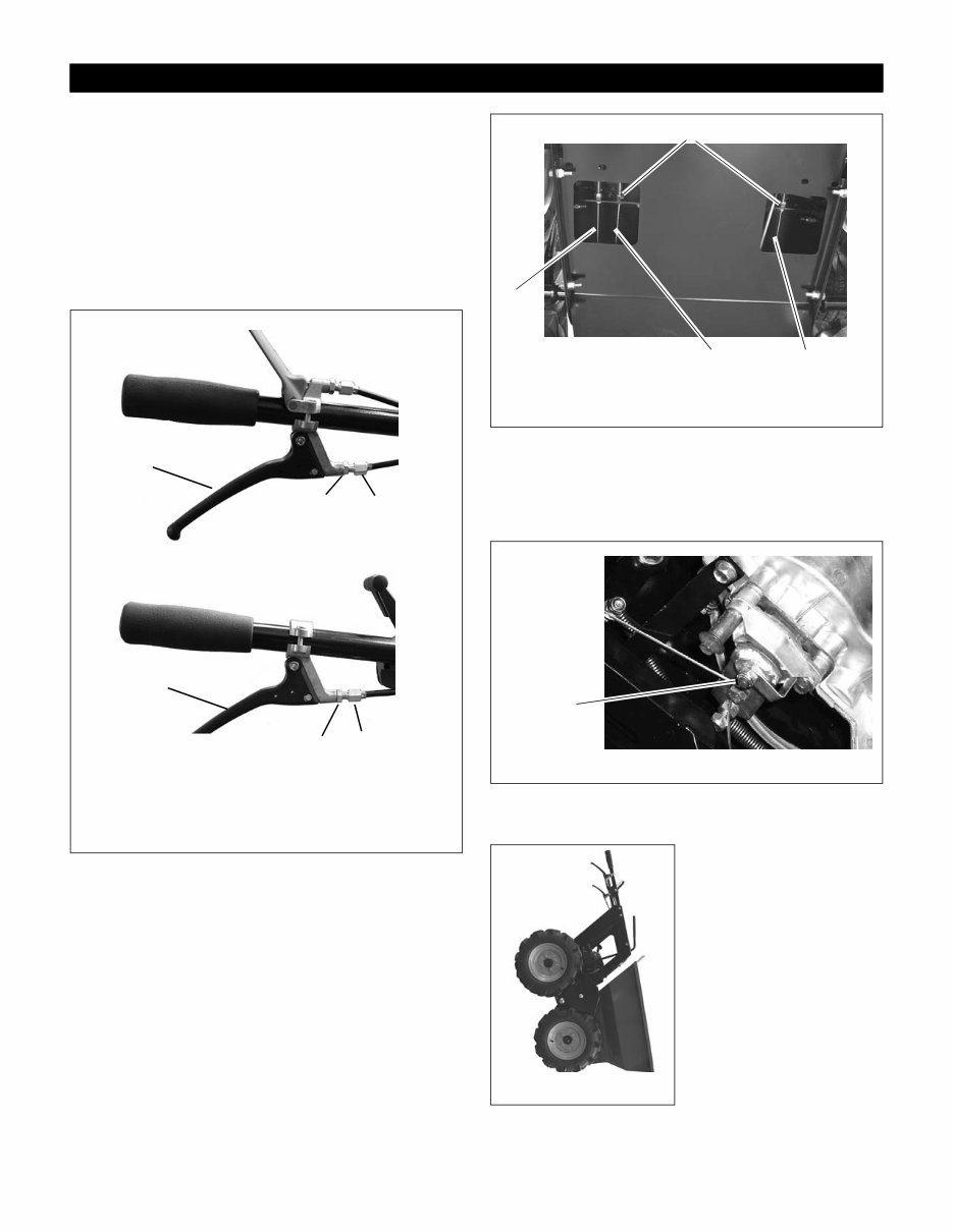
LEVER ADJUSTMENTS
(Figure 10)
Primary clutch and skip release cable adjustments are
made at the levers. To adjust:
1. Loosen lock nut (item 1).
2. Adjust cable by rotating adjustment nut (item 2).
Moving adjustment nut away from the lever will
result in earlier engagement. Handlebar
3. Tighten lock nut.
ADDITIONAL ADJUSTMENTS
(Figure 11)
If clutch,or skip release cable adjustments at the levers
are insufficient, additional adjustments can be made to
the cables under the unit:
1. Place unit in service position (See Service Position
in this section).
2. Loosen lock nuts on the cable.
3. Adjust cable to desire position.
4. Tighten lock nuts.
Parking Brake Disc
(Figure 12)
If the cable adjustments do not allow parking brake to
fully engage, tighten the lever attachment nut on the
transmission.
SERVICE POSITION
(Figure 13)
To access the drive belt and
cable attachment points
place the unit in the service
position by tipping it on its
front wheels and front skip
edge.
Be sure to move the fuel
shut-off valve to the closed
position before placing in
service position (see Fuel
Shut-Off Valve on page 7).
SERVICE AND ADJUSTMENTS
Figure 10
1. Lock Nut
2. Adjustment Nut
3. Clutch Lever
4. Skip Release Lever
1
2
1 2
4
3
Left Handlebar
Right Handlebar
Figure 11
1. Parking Brake Cable
2. Clutch Cable
3. Skip Release Cable
4. Lock Nut
1
2
3
4
Figure 12
Tighten to
increase
parking brake
pressure.
Figure 13
GB – 10
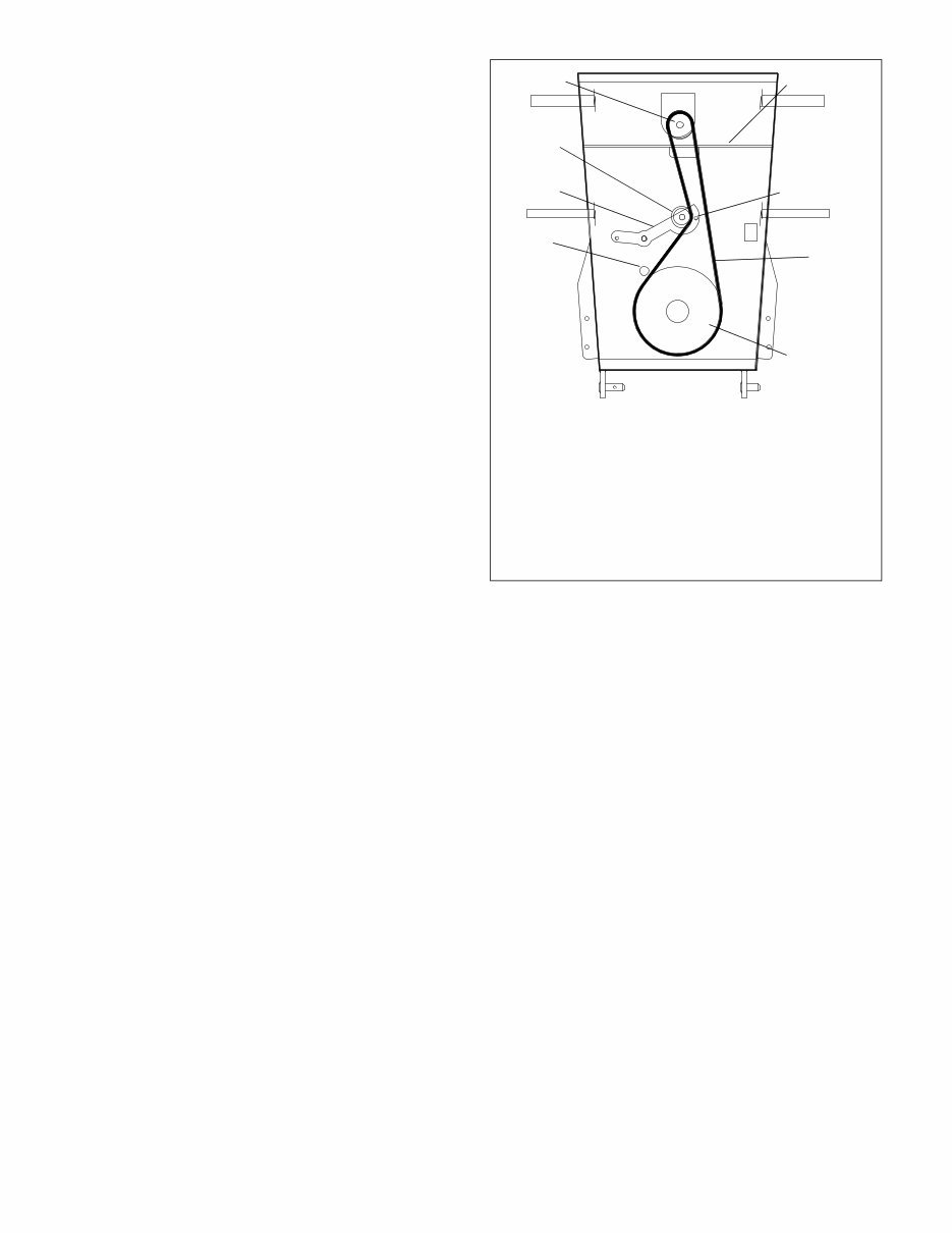
DRIVE BELT REPLACEMENT
(Figure 14)
Removal
1. Remove two 5/16" hex bolts retaining bottom panel
at front of unit.
2. Place unit in service position (see SERVICE
POSITION above).
3. Remove remaining four 5/16" hex bolts retaining
the bottom panel and remove the panel.
4. Loosen the hex nut retaining the belt guide tube
(item 1) enough to allow belt to be removed from
transmission pulley (item 2).
5. Remove the belt guide bolt (item 7) from the idler
arm (item 4).
6. Remove the belt from the unit.
Installation
1. Install replacement belt on transmission pulley
(item 2).
2. Tighten belt guide tube (item 1).
3. Route belt to right side of idler pulley (item 3). Outer
flat portion of belt will contact pulley.
4. Install idler belt guide bolt (item 7).
5. Route belt through opening in reinforcing plate
(item 6) and onto engine pulley (item 8).
6. Adjust clutch as needed. See LEVER
ADJUSTMENTS on page 9.
7. Install bottom panel.
Figure 14
1. Belt Guide Tube
2. Transmission Pulley
3. Idler Pulley
4. Idler Arm
5. Drive Belt
6. Reinforcing Plate
7. Idler Belt Guide
8. Engine Pulley
3
1
6
7
5
2
4
8
You're Reading a Preview
What's Included?
Fast Download Speeds
Online & Offline Access
Access PDF Contents & Bookmarks
Full Search Facility
Print one or all pages of your manual
$41.99
Muck Truck Mk IV Dumper Accessories & Parts Manual
Viewed 69 Times Today

What's Included?
Fast Download Speeds
Online & Offline Access
Access PDF Contents & Bookmarks
Full Search Facility
Print one or all pages of your manual
$41.99

Secure transaction
What's Included?
Fast Download Speeds
Online & Offline Access
Access PDF Contents & Bookmarks
Full Search Facility
Print one or all pages of your manual
Description
The Muck Truck Mk IV Dumper and MAX Mk II Dumper Owner, Operation, Accessories & Parts Manual is an essential resource for both professional mechanics and DIY enthusiasts. This comprehensive manual provides detailed information on the owner's manual, operation manual, as well as accessories and parts for the Muck Truck Mk IV Dumper and MAX Mk II Dumper. Whether you're looking to understand the operational aspects or need to identify and procure specific parts and accessories, this manual is an invaluable tool for maintaining and repairing these vehicles.


