Volvo A30D Articulated Dump Truck Service Repair Shop Manual
What's Included?
Lifetime Access
Fast Download Speeds
Offline Viewing
Access Contents & Bookmarks
Full Search Facility
Print one or all pages of your manual
Service Information Document Title: Function Group: Information Type: Date: Hydraulic system, description 900 Service Information 2014/8/21 Profile: ART, A30D [GB] Hydraulic system, description See . 990 Hydraulic diagram, complete The hydraulic system consists of five [ 1] respectively six [ 2] hydraulic pumps, piston type pumps with continuously variable displacement. There are two (1) respectively three(2) pumps for the steering and dumping systems, two for fan drive and one ground dependent hydraulic pump on the dropbox. The ground dependent pump delivers oil via a non-return valve to the hydraulic system when the machine is moving forward. The dumping system is connected in parallel and series with the steering system, and have common hydraulic pumps. However, the steering system has priority over the dumping system to safeguard the steering function at all times. When only dumping, all pumps (except ground dependent pump) provide flow to the dumping system, When steering, a hydraulic pump is connected directly to the steering system, and thus, it is possible to steer and dump at the same time. Speed control of the fans takes place via a control valve on the pumps, which receives signals from the vehicle electronics. The electronics sense the temperature in the various cooling systems and variably adjusts the fan speed between base speed and max. speed. This is controlled electrically. In case of missing signal from the electronics, the fans are controlled to max. speed. See further in Section 2 and 3. The dumping system is servo-operated and is controlled with hydraulic oil from the dumping valve. The dump lever has four positions: lower with pressure, lower/float, hold and dump. The lever has fixed positions in lower/float or hold. When the current is cut off or the operator leaves the operator's seat, the lever automatically goes to the hold position. The lever can be locked in the hold position with a lock device. The dumping valve is a load-sensing 4-way valve. The valve slide has four positions: lower with pressure, lower/float, hold and dump. Operation of the dumping valve can be forced (lower/float position) using an adjusting screw at one end if there is no servo pressure for the dump lever. See .. 951 Dump body alternative, lowering Both hoist cylinders are of single-stage double-acting type.
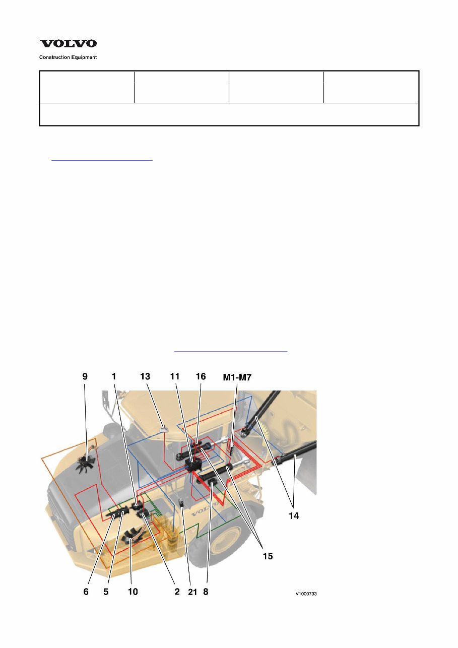
Figure 1 Hydraulic system, overview The list is according to 990 Hydraulic diagram, complete 1. 2. 3. 4. 5. 6. 7. 8. 9. 10. 11. 12. 13. 14. 15. 16. Hydraulic pump, engine dependent for steering and dumping systems Hydraulic pump, engine dependent for steering and dumping systems – Hydraulic pump, engine dependent for steering and dumping systems Hydraulic pump, engine dependent for intercooler fan motor Hydraulic pump, engine dependent for radiator fan motor – Hydraulic pump, ground dependent for steering Fan motor, intercooler Fan motor radiator Steering and dumping valve – Dump lever Hoist cylinders Steering cylinders Damping cylinder, steering 21. Pressure filter between fan motor and ground dependent pump M1–M7 Pressure check connections 1–7 [ 1]Applies to machines from and incl. serial number: EU A25D 11731–, A30D 10369– Brazil A25D 71001–, A30D 70001– [ 2]Applies to machines from and incl. serial number: EU A25D –11730, A30D –10368 US A25D –61118, A30D –60093
Service Information Document Title: Function Group: Information Type: Date: Hydraulic and servo systems, description 900 Service Information 2014/8/21 Profile: ART, A30D [GB] Hydraulic and servo systems, description Dump lever The steering and dumping valve includes a pressure reducing valve (R35), see . R35 reduces 990 Hydraulic diagram, complete the pressure from the hydraulic pumps to a servo pressure up to the dump lever. There are two valves in the dump lever, one for dumping and one for lowering. Depending on the position of the dump lever, the position of the valves changes and required servo pressure is delivered out to both ends of the dumping slide, which then changes position. The dump lever has four positions: Lower with pressure Lower/float (operating position) Hold position Dumping position In lever position ”hold”, both valves in the dump lever are unaffected. For more information about the dump lever and its function, see and 914 Dump lever, description . 990 Hydraulic pressure, specifications
Service Information Document Title: Function Group: Information Type: Date: Hydraulic oil, description 900 Service Information 2014/8/21 Profile: ART, A30D [GB] Hydraulic oil, description The machine is standard-equipped with mineral-based hydraulic oil and bio–oil is available as an option. The hydraulic oil contains selected additives that give good oxidation stability, good corrosion protection and good lubricating characteristics.
Service Information Document Title: Function Group: Information Type: Date: Hydraulic oil, storing and handling 900 Service Information 2014/8/21 Profile: ART, A30D [GB] Hydraulic oil, storing and handling Hydraulic oil should be stored in tightly sealed tanks or barrels. Only containers intended for transport of hydraulic oil may be used for this purpose. Hydraulic oil should be stored indoors or in temperature-controlled facilities. If hydraulic oil is stored outdoors, the barrels should be stored horizontally to prevent penetration of water and eradication of barrel markings. In order to avoid condensation, oil should not be stored in temperatures above 60 °C (140 °F), or be exposed to intense sunshine or cold temperatures.
Service Information Document Title: Function Group: Information Type: Date: Hydraulic components, cleanliness when handling 900 Service Information 2014/8/21 Profile: ART, A30D [GB] Hydraulic components, cleanliness when handling WARNING Hot hydraulic oil and hydraulic oil under pressure may result in severe personal injuries NOTICE It is very important to keep the hydraulic system free from any impurities, as these can cause abnormal wear and may lead to expensive downtime. Greatest possible cleanliness should be maintained during all handling of hydraulic components and hydraulic oil. NOTE! A vacuum pump should be used for work on the hydraulic system in order to avoid oil spills.
Service Information Document Title: Function Group: Information Type: Date: Hydraulic system, repair of hydraulic components in workshop 900 Service Information 2014/8/21 Profile: ART, A30D [GB] Hydraulic system, repair of hydraulic components in workshop Always wear clean coveralls and maintain strict personal cleanliness. Work with hydraulic components should be performed separate from other work in the shop, in a so-called "clean room". The room should have good ventilation and the floor should be coated with a binding material. Machining, grinding, etc. must not be performed in the "clean room". The workplace should be equipped with thoroughly cleaned tools and suitable containers for cleaning hydraulic components. Containers used for cleaning hydraulic components must not be used for other cleaning. The containers should be cleaned often and filled with new fluid. Clean all components that are going to be handled in the "clean room". Do not use caustic soda solutions or similar, which will result in corrosion. Always plan work on the hydraulic system so that it can be completed without long interruptions. When cleaning during repairs – use dry and clean compressed air for drying, not rags. When work is completed, always plug components with clean plastic plugs of suitable dimensions and package them. When cleaning the "clean room" – use methods that do not stir up dust and dirt.
Service Information Document Title: Function Group: Information Type: Date: Hydraulic components, storage and transport 900 Service Information 2014/8/21 Profile: ART, A30D [GB] Hydraulic components, storage and transport All hydraulic components should be stored in plastic bags or plastic foil and they should be plugged. The packaging must not be opened until the component is to be used. Service vehicles should be equipped with an interior which facilitates good order and cleanliness. Each service vehicle should have a roll of plastic foil, plastic plugs of the most common dimensions and plastic containers for components. Plugs and foil should be of the disposable type, that is, for one-time use only.
Service Information Document Title: Function Group: Information Type: Date: Pressure build-up, engine- dependent pumps, description 900 Service Information 2014/8/21 Profile: ART, A30D [GB] Pressure build-up, engine-dependent pumps, description The pumps are numbered according to the inputs to the steering and dumping valve. The engine is running and the machine is parked. The figures in the text below refer to the 990 Hydraulic diagram, complete The engine-dependent hydraulic pumps draw hydraulic oil from the hydraulic tank and build up a pressure to the steering and dumping valve 11 (neutral position). The pumps are connected with each other via ducts in the steering and dumping valve. Pump 2 is in contact with the dumping valve spool through the "open centre" of the steering valve spool, but when the steering spool is drawn from its neutral position BV2 prevents the oil flow from pump 2 from going to the dumping function. In this way the steering is prioritised. All oil from pump 2 then goes to the steering. The remaining engine- dependent pumps are in direct connection (past the steering valve spool) to the dumping valve spool and pressure reducing valve R35 for servo pressure to dumping control 13. Pressure is built up to the steering and dumping valve and its non-return valves. The pump compensator valve is acted upon through the pump's internal ducts and the pump angles downwards. Stand-by pressure now exists at the valve. The pressure in this phase is approx. 1.6 MPa (16 bar) (230 psi) and is only determined by the spring force in the compensator valve as no pressure from the steering system to the compensator LS–connection is obtained yet. In neutral position the steering and dumping valve permits a small controlled oil flow between its connection P2 and the connections A and B to the steering cylinders. An equal oil flow is also permitted between the connections A – B and connection T4 for the tank line. The pressure is built up to the steering cylinders 15, the damping cylinder 16, the shock valves CHV1 and CHV2 with anti-cavitation valves and the cross-over valves VV1 and VV2. The steering is stabilised by pressurising the steering cylinders. Pressure is also built up via the non-return valves BVLS1, BVLS2 and BVLS5 to output C2 and the compensator LS– connection on the engine-dependent pumps. The pressure in the pumps rises to a corresponding degree. At the same time oil is forced out from the steering and dumping valve connections A and B via back-pressure valve (MTRV1) against its spring force of approx. 1.8 MPa (18 bar) (260 psi) to its connection T4 and is returned to the tank. Pressure is also built up via BVLS3 and BVLS4 when oil is forced out from the steering and dumping valve connections B1- and A1+. The neutral position pressure at the outlet for the engine-dependent pumps is 3.5 ±0.5 MPa (35 ±5 bar) (510 ±73 psi), which is the total of the LS–pressure (MTRV 1's spring force)1.8 MPa (18 bar) (260 psi) and the spring pressure in the compensator valve 1.6 MPa (16 bar) (230 psi). P = pressure at pump outlet P = C + F C = pressure at LS–line F = spring pressure in the compensator valve
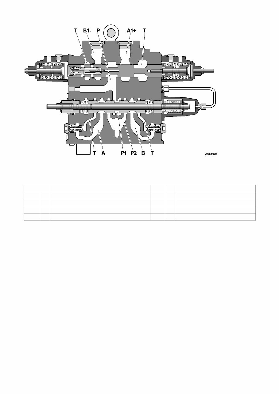
Figure 1 Steering and dumping valve connections Pos Description Pos Description A Connection to the steering cylinders P Pressure line A1+ Connection to the hoist cylinders P1 Pressure line B Connection to the steering cylinders P2 Pressure line B1- Connection to the hoist cylinders T Connection to the tank Pressure build-up, ground-dependent pump 8 The engine is running and the machine moves forwards. The engine-dependent pumps and the ground-dependent pump use common LS–pressure. The operation of the ground- dependent pump 8 is directly connected to the wheels via the drivetrain to the dropbox power take-off. When pump 8 rotates in the correct direction (the machine is driven forwards) pressure is built up to non-return valve BV4 in the steering and dumping valve. The pump's compensator valve is acted upon via internal ducts and the pump angles down as no oil flow arises. The same neutral position pressure now exists at the outlet of all of the pumps. Steering function, engine-dependent pumps The steering valve spool is displaced inwards and the connections P1– P4 from the pumps (also pump 8) are now in connection with the steering cylinders via connection A. Pressure is built up in the cylinders' A–connection and the pistons are acted upon on the plus side and minus side respectively. Pressure is built up simultaneously via the cross-over valves VV1 and VV2 to damping cylinder 16 and to the valve spool end face. The valve spool is stabilised. The same pressure is now also in the LS–line to the compensator's LS–connection. The compensator valve is acted upon and adapts the flow of the pumps to existing requirements. Pressure sensor SE9102 and pressure sensor SE9103, description of operation and checking Hydraulic pressures are monitored electronically using pressure sensor SE9102 for the engine-dependent pumps and SE9103 for the ground-dependent pump. See also Section 3. Restrictions C2 and C3 in load signal block 12 If leakage arises on the LS–line between C2 and the engine dependent pumps (indicator light for normal steering system not working lights up) then the LS–pressure to the secondary steering pump (ground-dependent) is maintained to some extent thanks to restriction C2. The secondary steering pump can thus supply the necessary flow to the steering valve. The opposite applies for C3 if leakage arises on the LS–signal line between C3 and the secondary steering pump.
Get your hands on the Volvo A30D Articulated Dump Truck Service Repair Shop Manual for comprehensive and detailed repair instructions. Whether you're a professional mechanic or a DIY enthusiast, this manual is designed to save you money by enabling you to perform your own repairs with ease.
Featuring step-by-step instructions, wiring diagrams, and detailed pictures, this manual covers all servicing and repair jobs, including routine maintenance. It is available in English and is compatible with Win/MAC/Linux systems.
With instant delivery upon receipt of payment, there are no shipping costs or waiting for the mailman. You can access the manual instantly on your PC, tablet, or laptop, making it convenient and easy to use.
FAQ: Why should I purchase this manual?
This manual provides an easy layout format that covers all repair procedures in great detail, helping you better understand all the parts and repair procedures. With the knowledge contained within this manual, you will be able to perform your own servicing, maintenance, and repairs.
FAQ: What models are covered in this manual?
All models for the specified years and all engine types are included in this manual.
FAQ: What type of information is covered?
Every manual is packed with all aspects of service, repair, and maintenance.
FAQ: How long for delivery?
Delivery on this item is instant once you have paid with your Credit/Debit/Paypal Account, with no shipping involved. You will receive this manual right away, allowing you to start your repair today.
FAQ: How much money will I save?
This manual will help you save money upwards into the thousands, empowering you to avoid overpriced services and perform small jobs yourself using the information and knowledge contained in this manual.
FAQ: Is this manual hard to use?
No, not at all. If you can open up an email, then you can use this manual. It's that simple! This manual is in .PDF format and will work on any PC/MAC computer.
Recently Viewed
5,521,897Happy Clients
2,594,462eManuals
1,120,453Trusted Sellers
15Years in Business
Price:
Actual Price:
Volvo A30D Articulated Dump Truck Service Repair Shop Manual