CUSTOMER SUPPORT DEPARTMENT TEREX EQUIPMENT LIMITED MOTHERWELL, SCOTLAND ML1 5RY REF. NO. SM820 SM 2345 06-05 TA40 OCDB (A820) Articulated Dumptruck Maintenance Manual CLICK HERE FOR TABLE OF CONTENTS CLICK HERE TO RETURN TO MAIN LIBRARY INDEX Part No. 15275763
TEREX SERVICE DEPARTMENT PURPOSE: To advise potentially hazardous condition. DETAIL: It has been brought to our attention that 'Viton' material used in manufacture of oil seals and 'O' rings, produces a highly corrosive acid (Hydrofluoric) when subjected to temperatures above 315° C. The resulting contamination can have extreme consequences on human tissue since it is almost impossible to remove after contact. We therefore recommend the following procedure when it is necessary to inspect any equipment that has been subjected to a high temperature i.e. fire. a. Visually inspect for any gaskets or seals which have suffered from heat; they will appear black and sticky. b. If this is affirmed - Do Not Touch c. Make enquiries to ascertain the material composition. Any Fluoro-elastomer (Viton, Fluorel or Tecmoflon) should be considered dangerous but natural rubber and nitrile are non-hazardous. d. If Fluoro-elastomer seals have been used, then the affected area MUST be decontaminated before undertaking further work. e. Disposable Heavy Duty Gloves (Neoprene) MUST be worn and the affected area decontaminated by washing thoroughly with Limewater (Calcium Hydroxide solution). f. Any cloths, residue and gloves used MUST be safely discarded after use. Note: Burning of the discarded items is NOT RECOMMENDED, except in an approved incineration process where the gaseous products are treated by alkaline scrubbing. Service Information Alert DATE: April 1994 B168 MODEL: General SUBJECT: VITON 'O' RINGS AND SEALS (FLUORO-ELASTOMERS) - SAFETY HAZARDS TEREX Equipment Limited, Motherwell, Scotland ML1 5RY Tel. (0698) 732121 Tlx. 77141 Fax. (0698) 734046 TEREX Division, Tulsa, Oklahoma, 74107 USA Tel. (918) 446-5581 Fax. (918) 446-9752 The information contained within this Alert must not be made available to third parties not authorised to receive it.
SM 222 Rev 1 Proper service and repair is important to the safe, reliable operation of all motor vehicles. The service procedures recommended and described in this publication, are effective methods for performing service operations. Some of these service operations require the use of tools specially designed for the purpose. The special tools should be used when, and as recommended. It is important to note that this publication contains various WARNINGS and NOTES which should be carefully read in order to minimize the risk of personal injury to personnel, or the possibility that improper service methods will be followed which may damage the vehicle or render it unsafe. It is also important to understand these WARNINGS and NOTES are not exhaustive. It is not possible to know, evaluate and advise the service trade of ALL conceivable ways in which service might be carried out, or, of the possible hazardous consequences of each way. Consequently, no such broad evaluation has been undertaken. Accordingly, anyone who uses a service procedure, or tool, which is not recommended, must first satisfy themselves thoroughly that neither their safety, nor vehicle safety, will be jeopardized by the service method he/she selects. Two types of heading are used in this manual to attract your attention. 1. WARNING - This symbol is used when an operating procedure, practice, etc., which, if not correctly followed could result in personal injury or loss of life. Look for this symbol to point out important safety precautions. It means - ATTENTION! BECOME ALERT! YOUR SAFETY IS INVOLVED! 2. Note - This is used when an operating procedure, practice, etc., which, if not strictly observed, could result in damage to or destruction of equipment. IMPORTANT SAFETY NOTICE WARNING Never use parts which are altered, modified, or weakened in operation. This can seriously jeopardize the integrity of the machine and could result in property damage or serious personal injury.
SM 2146 Rev 10 06-05 1 TABLE OF CONTENTS Section No. Description SM No. 000 GENERAL INFORMATION 0000 Technical Data - TA40 2110 Rev 4 0010 Welding Procedure 2172 100 CHASSIS 0010 Frames 1372 Rev 1 0020 Articulation and Oscillation Pivot 1373 Rev 2 0040 Hood and Mounting 2120 110 ENGINE 0030 Engine and Mounting 2121 Rev 1 0050 Air Cleaner 2122 Rev 1 120 TRANSMISSION 0010 Transmission and Mounting 2124 Rev 3 130 DRIVELINES 0010 Front Drivelines 1378 Rev 2 0020 Rear Drivelines 1379 Rev 2 140 FRONT AXLE GROUP 0020 Axle Group (Hub) (Refer to Section 160-0030) - 0040 Wheel Rim and Tyre (Refer to Section 160-0050) - 0060 Differential Drive Head 2148 150 CENTRE AXLE 0020 Differential Drive Head 2149 160 REAR AXLE GROUP 0020 Differential Drive Head 2151 0030 Axle Group (Hub) 2147 Rev 1 0050 Wheel Rim and Tyre 1382 Rev 1 165 BRAKE ASSEMBLY 0015 Oil Cooled Disc Brakes 2167 Rev 1 170 PARKING BRAKE 0010 Parking Brake and Mounting 2253 0030 Actuator 2166 Rev 1 180 SUSPENSION SYSTEM 0020 Front Suspension 2119 0040 Rear Suspension From A8201011 to A8201230 1384 Rev 2 0040 Rear Suspension From A8201231 2340 190 ELECTRICAL SYSTEM 0000 Circuit Diagrams (DDEC IV, 6WG 310 transmission) 2126 Rev 2 0270 Switches and Sensors 2252 200 FUEL SYSTEM 0040 Fuel System 1398 Rev 1 0051 Electronic Foot Pedal 1399
SM 2146 Rev 10 06-05 2 * * * * TABLE OF CONTENTS Section No. Description SM No. 210 COOLING SYSTEM 0000 Cooling System (Series 60 Engine) 2117 Rev 1 0005 Cooling System Schematic 2154 Rev 1 0010 Cooling Fan and Motor 2116 0040 Radiator and Mounting 2118 Rev 1 0045 Low Temperature Unloader Valve 2152 0046 Low Pressure Relief Valve 2164 Rev 1 0050 Disc Brake Oil Cooler 2153 0060 Transmission Oil Cooler 1922 Rev 2 0100 Hydraulic Oil Cooler 1403 Rev 1 220 STEERING SYSTEM 0000 Steering System Schematic 1390 Rev 2 0090 Steering Valve 1391 0100 Flow Amplifier Valve 1392 Rev 3 0120 Steering Cylinder 1393 Rev 1 0140 Emergency Valve 1395 Rev 1 230 BODY SYSTEM 0000 Body System Schematic 1407 Rev 2 0040 Hydraulic Tank 1913 Rev 2 0050 Main Hydraulic Pump 1394 Rev 1 0060 Body Control Valve 1410 Rev 2 0081 Body Control Joystick 1411 Rev 2 0121 Pilot Supply Valve 1448 Rev 1 0130 Body Cylinder 1409 Rev 1 250 BRAKING SYSTEM 0000 Braking System Schematic 2155 Rev 1 0025 Brake Coolant Tank 2156 0040 Triple Pump 2157 0045 Motor/Triple Pump Assembly 2162 0050 Brake Manifold Valve 2158 0060 Accumulator 2160 0065 Two Speed Control Valve 2159 0070 Treadle Valve 2165 Rev 1 0075 Priority Unloader Valve 2161 0090 Directional Control Valve 2254 0120 Relief Valve 2163 260 OPERATORS COMPARTMENT 0010 Cab and Mounting 1404 Rev 1 0090 Driver Seat and Mounting 1981 0130 Air Conditioning 1405 Rev 2 270 BODY 0010 Body and Mounting 1406 Rev 1 300 MISCELLANEOUS 0020 Lubrication System 2129 Rev 4 0070 Service Tools 1419 Rev 4 0080 Standard Bolt and Nut Torque Specifications 1238 0090 Unit Storage 1239
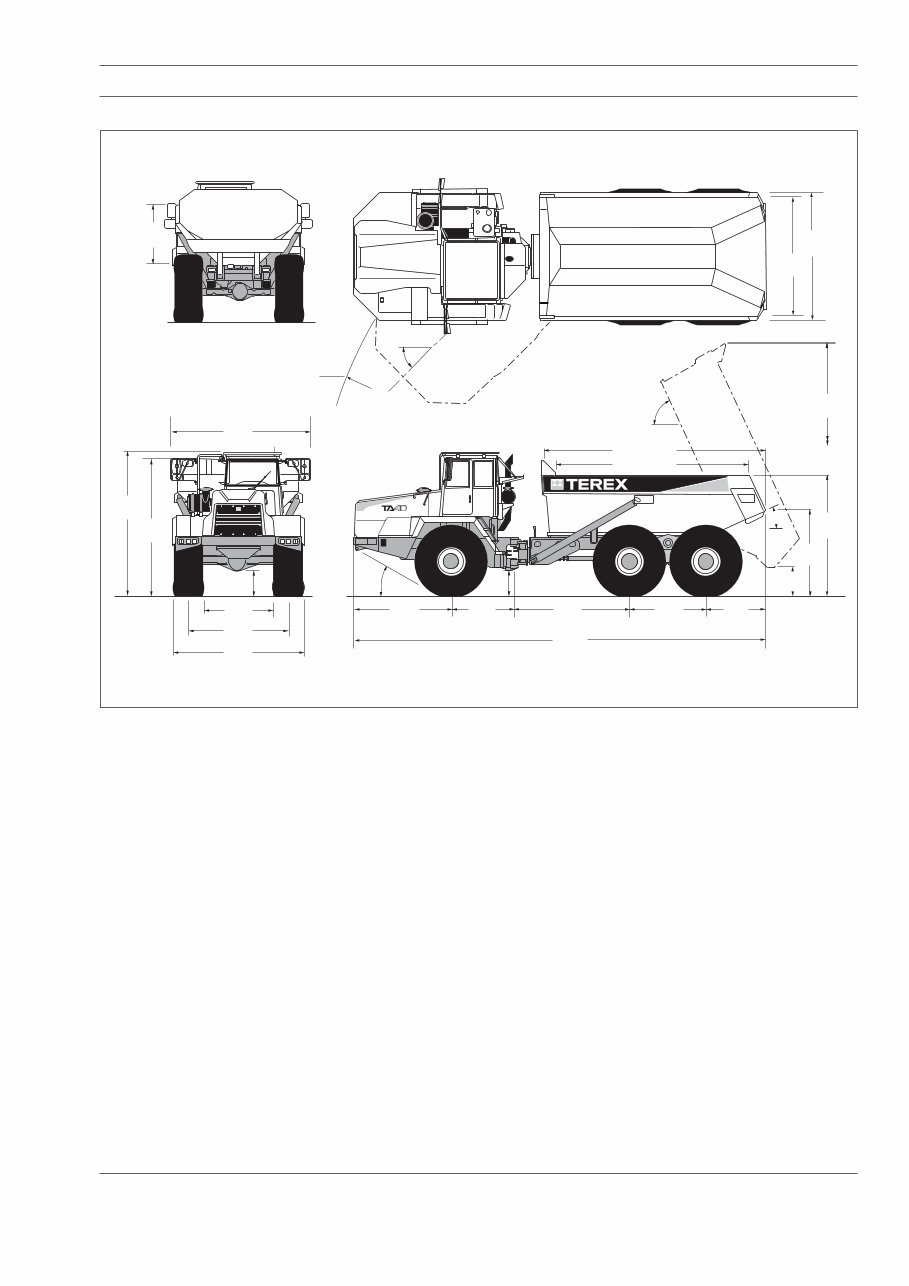
1 Section 000-0000 SM 2110 Rev 4 03-05 Dimensions in mm (ft-in) 3 020 (9-11) 3 220 ( 10-7 ) 45˚ Vehicle Clearance Turning Diameter 19.5m (64ft) 3 430 (11-3) 3 720 (12-2) 560 (1-10) 3 450 (11-4) 3 670 (12-0) 2 540 (8-4) 1 600 (5-3) 3 000 (9-10) 10 650 (34-11) 28˚ 6 500 (21-4) 5 700 (18-8) 65˚ 2 240 (7-4) 675 (2-3) 3 100 (10-2) 25˚ 1 540 (5-0) 1 970 (6-6) 5 370 (17-7) Max Body Depth 1 450 (4-9) 2 640 (8-8) 1 810 (5-11) 525 (1-9) SM - 3303 GENERAL INFORMATION - Technical Data ENGINE Make/Model .................................... Detroit Diesel Series 60 Type .............. Four cycle diesel, turbocharged with air-to-air charge cooling, water cooled. Electronic management. Gross power at 2 200 rev/min ...... 332 kW (445 hp, 451 PS) Net power at 2 200 rev/min .......... 291 kW (390 hp, 395 PS) Note: Net power is after deductions for alternator. Engine emission meets Tier II USA EPA/CARB MOH 40 CFR 89 and EU NRMM (non-road mobile machinery) directive. Maximum Torque .............................. 2 000 Nm (1 475 lbf ft) at 1 350 rev/min Number of cylinders/configuration ............ 6 cylinder, in line Bore and Stroke .................... 130 x 160 mm (5.12 x 6.30 in) Total Displacement ................................. 12.7 litres (774 in³) Air cleaner .................................... Dry type, double element Starting ..................................................................... Electric Maximum Speed (No load) ............................ 2 325 rev/min Maximum Speed (Full load) ........................... 2 200 rev/min Idle Speed ......................................................... 700 rev/min Maximum Operating Slope ........................ 30° (57% Grade) TRANSMISSION Make/Model ..................................... ZF 6WG 310 Automatic with manual override. The transmission consists of a torque converter close-coupled to a 6 speed gearbox with integral output transfer gearing. Automatic shifting throughout the range, with kickdown feature. Lockup in all forward gears. A torque-proportioning output differential transmits drive permanently to front and rear axles. This differential may be locked by the driver for use in difficult traction conditions. Integral hydraulic retarder. Pressures: Main ....................................... 16 + 2 bar (232 + 30 lbf/in²) Lockup (Wk) ........................ 14 + /- 1 bar (190 + /- 15 lbf/in²) Converter 'IN' ........... 7.6 bar (110 lbf/in²) at 2 300 rev/min Converter 'OUT' .......... 4.8 bar (70 lbf/in²) at 2 300 rev/min Converter Relief Valve ....................... 8.5 bar (123 lbf/in²) Retarder ................................................... 6 bar (87 lbf/in²) Temperatures: Normal ................................... 80° - 110° C (176° - 230° F) Maximum .................................................. 120° C (248° F) Stall Speed ............................................. 1 835 ± 50 rev/min Fig. 1 - Machine Dimensions
General Information - Technical Data Section 000-0000 SM 2110 Rev 4 03-05 2 BRAKES Full hydraulic braking system with enclosed, forced oil- cooled multiple discs on each wheel. Independent circuits for front and rear brake systems. Warning lights and audible alarm indicate low brake system pressure. Brake system conforms to ISO 3450, SAE J1473. Actuating Pressure ........... 138 ± 6.2 bar (2 000 ± 90 lbf/in²) Pump Type ................................................ Triple stage gear Capacity at 2 200 rev/min ...... 2.02 litre/s (32 US gal/min) combined Braking surface (tractor) ..... 802837 mm 2 (1244.4 in 2 )/brake Braking surface (trailer) ........ 535225 mm 2 (829.6 in 2 )/brake Parking: Spring-applied, hydraulic-released disc on rear driveline. Emergency: Automatic application of driveline brake should pressure fall in main brake hydraulic system. Service brakes may also be applied using the parking-emergency brake control. Retardation: Hydraulic retarder integral with transmission. WHEELS AND TYRES Wheels ...... Five-piece Earthmover rims with 23 Stud Fixing Size: Standard ....................... 25 x 25.00 in for 29.5 R25** tyres Tyres: Standard ............................................... 29.5 R25** Radial Inflation Pressures (Bridgestone): Front Rear 29.5 R25** 3.5 bar (51 lbf/in²) 4.25 bar (62 lbf/in²) Inflation Pressures (Continental): Front Rear 29.5 R25** 3.5 bar (51 lbf/in²) 4.25 bar (62 lbf/in²) Inflation Pressures (Michelin): Front Rear 29.5 R25** 3.0 bar (44 lbf/in²) 3.65 bar (53 lbf/in²) Note: Tyre pressures should be regarded as nominal only. It is recommended that for tyres both listed and unlisted, the user should consult the tyre manufacturer and evaluate all job conditions in order to make the proper selection. HYDRAULIC SYSTEM Steering and Body Hoist Ratios: Torque Converter .................................................... 1.84:1 Transmission .................................... Refer to table below. Forward Gear 1 2 3 4 5 6 Ratio 5.35 3.45 2.21 1.42 0.97 0.62 km/h 6.0 9.3 14.6 22.7 33.3 51.7 mile/h 3.7 5.8 9.1 14.1 20.7 32.1 Reverse Gear 1 2 3 Ratio 5.35 2.21 0.97 km/h 6.0 14.6 33.3 mile/h 3.7 9.1 20.7 Note: During reversing operations it is recommended to reduce engine speed, use only 1st or 2nd gear and never exceed 10 km/h (6.2 mile/h). AXLES Three axles in permanent all-wheel drive with differential coupling between each axle to prevent driveline wind-up. Heavy duty axles with fully-floating axle shafts and outboard planetary gearing. Automatic limited slip differentials in each axle. Leading rear axle incorporates a through-drive differential to transmit drive to the rearmost axle. Locking of this differential is actuated simultaneously with the transmission output differential lock. Ratios: Differential ............................................................... 4.86:1 Planetary ................................................................. 4.94:1 Total Reduction ....................................................... 24.0:1 SUSPENSION Front: Axle located by a leading A-frame permitting both vertical movement and oscillation. Rubber cone suspension medium with heavy duty hydraulic dampers. Axle Vertical Travel .................................. 105 mm (4.2 in) Rear: Each axle is coupled to the frame by three rubber- bushed links with lateral restraint by a transverse link. Pivoting inter-axle balance beams equalise load on each rear axle. Suspension movement is cushioned by rubber/ metal laminated compression units between each axle and underside of balance beam ends. Pivot points on rear suspension linkages are rubber-bushed and maintenance-free. Axle Vertical Travel ............................ ± 115 mm (± 4.5 in) Axle Oscillation ............................................................ ± 9° The steering and body hydraulic systems are supplied with oil from a common tank by the main hydraulic gear pump. Pump is driven from power takeoff on transmission. The components are protected by advanced full flow filtration to 5 micron particle size on the return line. Pump capacity (at 2258 rpm)....................... 7.03 litre/s (111 US gal/min)
You're Reading a Preview
What's Included?
Lifetime Access
Fast Download Speeds
Online & Offline Access
Access PDF Contents & Bookmarks
Full Search Facility
Print one or all pages of your manual
$40.99$53.99
Terex TA40 OCDB Articulated Dump Truck Service Repair Shop Manual
The Terex TA40 OCDB Articulated Dump Truck Service Repair Shop Manual is a comprehensive resource designed for both professional mechanics and DIY enthusiasts. It provides detailed instructions, diagrams, and pictures to facilitate easy repairs and maintenance for all areas of the vehicle.
This manual covers all servicing and repair jobs, including routine maintenance, for all models and engine types within the specified years. It is available in English and is compatible with Win/MAC/Linux systems.
With instant delivery upon receipt of payment, there are no shipping costs or waiting for the mailman. You can access the manual immediately on your PC, tablet, or laptop. The manual's easy layout format ensures that all repair procedures are covered in great detail, allowing you to better understand the vehicle's parts and repair processes.
Instant delivery upon receipt of payment
No shipping costs
Compatible with Win/MAC/Linux
By using the information and knowledge contained in this manual, you can save a significant amount of money by performing repairs and maintenance yourself, avoiding overpriced services from mechanics, technicians, or engineers. The manual is user-friendly and will work on any PC/MAC computer, making it accessible to all users.
Get started on your vehicle repair today and save money with the comprehensive Terex TA40 OCDB Articulated Dump Truck Service Repair Shop Manual.
Reviews
Q&A
Recently Viewed
5,521,897Happy Clients
2,594,462eManuals
1,120,453Trusted Sellers
15Years in Business
Price:
Actual Price:
Terex TA40 OCDB Articulated Dump Truck Service Repair Shop Manual