1 MHTOC4 01/17/2006 TEREX|UNIT RIG MT 4400AC MECHANICAL MANUAL MT 4400AC MECHANICAL MANUAL (MHTOC4) TABLE OF CONTENTS MHTOC4 INTRODUCTION M1605 SECTION 1 - DESCRIPTION AND OPERATION DESCRIPTION M1841 SAFETY M1582 PRE-OPERATIONAL INSPECTION M1583 OPERATION M1584 SECTION 2 - STRUCTURE MAIN FRAME M1599 SUPERSTRUCTURE M1600 LADDER AND RAILING ASSEMBLY M1610 HOOD ASSEMBLY M1611 CAB M1601 STEERING COLUMN ASSEMBLY M1602 CAB HEATER ASSEMBLY M1625 WINDSHIELD WIPER/WASHER SYSTEMS M1826 FUEL TANK M1603 DUMP BODY M1604 SECTION 3 - ELECTRICAL SYSTEM ELECTRICAL SYSTEM M1813 ELECTRICAL SCHEMATICS S10327; S10327Y; S10495 (S/N SPECIFIC) SECTION 4 - POWER PACKAGE AIR CLEANER M1020 ENGINE MODULE M1660 EXHAUST ASSEMBLY DUMP BODY HEATING M1861 MUFFLERS M1860 COOLING SYSTEM M1613 RADIATOR COOLING MODULE M1614 RADIATOR – MECHANICALLY BONDED CORE M1825 ALTERNATOR AND WHEELMOTOR COOLING M1850 SECTION 5 - HYDRAULIC SYSTEM HYDRAULIC SYSTEM M1849 HYDRAULIC FILTERS M1597 HYDRAULIC TANK M1620 HYDRAULIC PUMP DRIVE ASSEMBLY M1621 DUMP SYSTEM M1760 DUMP PUMP M1687 DUMP CONTROL VALVE M1590 DUMP PILOT VALVE M1591 DUMP CYLINDER M1619 STEERING SYSTEM M1759 STEERING PUMP M1592 STEERING ACCUMULATORS M1593 STEERING HAND PUMP M1594 STEERING FLOW AMPLIFIER VALVE M1595
2 MHTOC4 01/17/2006 SECTION 5 - HYDRAULIC SYSTEM (CONTINUED) STEERING CYLINDER M1596 STEERING SYSTEM MANIFOLD M1720 MANUAL POWER SUPPLY PUMP M1761 BRAKE SYSTEM M1847 BRAKE ACCUMULATORS M1740 BRAKE PEDAL VALVE ASSEMBLY M1509 BRAKE CONTROL VALVE M1542 BRAKE SYSTEM MANIFOLD M1678 PARK BRAKE SOLENOID VALVE M1680 SHUTTLE VALVE M1865 SECTION 6 - PNEUMATIC SYSTEM PNEUMATIC SYSTEM M1609 SECTION 7 - RUNNING GEAR FRONT AXLE FRONT AXLE ASSEMBLY M1572 FRONT WHEEL ASSEMBLY (GREASE LUBRICATED BEARINGS) M1842 FRONT WHEEL ASSEMBLY (OIL LUBRICATED WHEEL BEARINGS) M1843 FRONT SUSPENSION ASSEMBLY M1637 STEERING LINKAGE M1574 REAR AXLE AXLEBOX ASSEMBLY M1575 REAR SUSPENSION ASSEMBLY M1638 WHEELMOTORS M1814 TIRES AND RIMS TIRE AND RIM ASSEMBLY M1157 LOCTITE PROCEDURES FOR WHEEL STUDS M1320 SECTION 8 - BRAKE SYSTEM FRONT AXLE CARLISLE (CARLISLE/GOODRICH) M1163 ROCKWELL (MERITOR/ROCKWELL/GOODYEAR) M1213 REAR AXLE CARLISLE (CARLISLE/GOODRICH) M1164 ROCKWELL (MERITOR/ROCKWELL/GOODYEAR) M1214 PARK BRAKES CARLISLE (CARLISLE/GOODRICH) M1183 ROCKWELL (MERITOR/ROCKWELL/GOODYEAR) M1452 SECTION 9 - OPTIONS LUBRICATION SYSTEM AUTOMATIC AUTOMATIC LUBRICATION SYSTEM (HYDRAULICALLY OPERATED ROTARY PUMP) M1756 HYDRAULICALLY OPERATED ROTARY GREASE PUMP M1757 INJECTORS M1623 CENTRAL SERVICE M1578 HUBODOMETER M1113 CIRCULATING ENGINE OIL SUPPLY SYSTEM M1703
3 MHTOC4 01/17/2006 TEREX|UNIT RIG MT 4400AC MECHANICAL MANUAL SECTION 10 - MISCELLANEOUS PREVENTIVE MAINTENANCE PREVENTIVE MAINTENANCE – TRUCK M1844 PREVENTIVE MAINTENANCE SCHEDULE - ELECTRIC DRIVE SYSTEM E1050 PREVENTIVE MAINTENANCE – WEIGH SYSTEM U2066 FIELD ASSEMBLY INSTRUCTIONS – MT 4400AC M1845 RECOMMENDED JACKING AND SUPPORT POINTS M1888 RECOMMENDED LUBRICANTS AND FLUIDS M1853 WELDING PROCESS FOR HIGH STRENGTH, LOW ALLOY STEELS M1315 STANDARD BOLT TORQUE M1116 METRIC CONVERSIONS M1115 STANDARD GRAPHIC SYMBOLS M1119 COMPONENT WEIGHTS M1846 STANDARD MAN-HOURS FOR COMPONENT REMOVAL & REPLACEMENT M1822
4 MHTOC4 01/17/2006
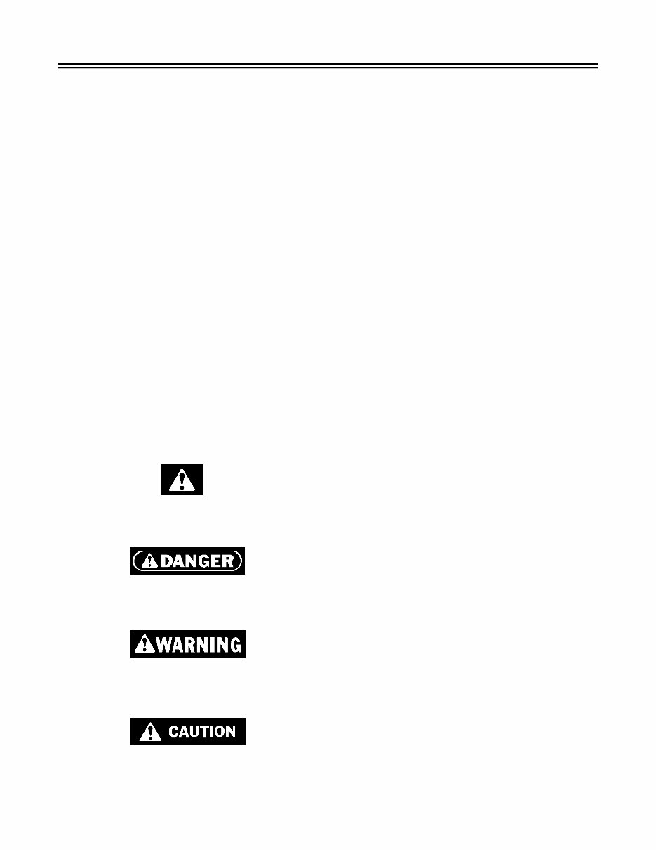
1 M1605 12/19/95 UNIT RIG INTRODUCTION INTRODUCTION This manual has been prepared to provide a descrip- tion, operation, servicing, and repair procedures for Lectra Haul vehicles manufactured by Unit Rig, Inc. Before attempting any maintenance on the truck, per- sonnel should become familiar with various systems and components and understand their operation and impor- tance. Information contained in this manual pertains to the mechanical aspects of the truck. For detailed infor- mation concerning the electrical systems and compo- nents, refer to the appropriate Unit Rig Electrical Main- tenance Manual or manufacturer’s information for the specific truck model and electrical propulsion system. The systems and schematics shown in this manual do not necessarily reflect all vehicle configurations. Con- sideration should be given to modifications and system changes which may have been made after purchase, or items unique to your application. The contents of this manual do not claim to cover all details or variations in equipment, nor provide for every possible contingency to be met in connection with main- tenance repair, or operation. Safety and informational highlights used in this manual include: This symbol means your safety is involved! Read, un- derstand and follow all Danger , Warning, and Caution decals on your machine and instructions in this manual. The signal word DANGER indicates an imminent haz- ard situation which, if not avoided, will result in death or serious injury. The signal word WARNING indicates a potentially haz- ardous situation which, if not avoided, could result in death or serious injury. The signal word CAUTION indicates a potentially haz- ardous situation which, if not avoided, may result in minor or moderate injury. It may also be used to alert against unsafe practices. The signal words IMPORTANT and NOTE indicate a operations, conditions, or specific information of suffi- cient importance to call for additional specific instruc- tions or information. SAFE POSITION DEFINITION In this manual a SAFE POSITION is defined as a park- ing position in which the truck cannot move even if all of the truck’s brakes are released. Three examples of a SAFE POSITION ARE: 1. The truck is driven into a ditch or over a berm line. or 2. The truck is driven up against a berm or bank. or 3. Chocks are placed in front of and behind the wheels. These chocks must be of sufficient size to hold the truck on the grade on which it is parked. Remember, the truck will be in a SAFE POSITION only if it is parked so that it cannot move even if the brakes are released. USE OF THIS MANUAL This manual has been prepared in modules (small, loose-leaf packets of information) to assist in keeping the information up-to-date and maintaining technical accuracy. It is designed to allow information to be changed on specific topics without upsetting other un- affected areas. The manual is divided into 10 sections: 1. DESCRIPTION AND OPERATION 2. STRUCTURE 3. ELECTRICAL SYSTEM 4. POWER PACKAGE 5. HYDRAULIC SYSTEM 6. PNEUMATIC SYSTEM 7. RUNNING GEAR 8. BRAKE SYSTEM 9. OPTIONS 10. MISCELLANEOUS All material covered in this manual are organized in one of these sections. Dividers are used to provide easy access to the first page of each section. A Table of Con-
2 M1605 12/19/95 tents located on the first page listing the modules in- cluded in that section. The remainder of the section consists of the individual modules (or packets of information). Each module is an individual “chapter” with the important maintenance in- formation of the topic of interest. They are prepared on systems, sub-systems, and individual components. Each module is further subdivided into topics as follows: 1. DESCRIPTION AND LOCATION 2. OPERATION 3. TROUBLESHOOTING 4. MAINTENANCE AND ADJUSTMENT 5. REMOVAL 6. DISASSEMBLY 7. INSPECTION AND REPAIR 8. ASSEMBLY 9. INSTALLATION All Table of Contents in this manual include this sys- tem. The modules themselves will be changed on their next update/modification. Illustrations, in the form of line drawings, cut-away views, photos, etc., are included to assist in the understanding of the test. Safety related items are identified by the DANGER, WARNING, CAUTION headings preceding the instructions or statements. Highlighted information is identified by the term IMPORTANT or NOTE preced- ing the text. Proper use of the manual will improve your ability to keep the truck operating safely and efficiently. When referring to the manual for information: 1. Determine what system or component is involved. 2. Determine what section you feel it would be orga- nized in. Remember, there are several possible sec- tions for many components. 3. Use the divider and turn to the Table of Contents on the first page of the section. 4. Use the Table of Contents to locate the appropriated module. If not listed in the Table of Contents, refer to another appropriate section and check again. 5. Locate the module in the section. 6. Read the Description and Location material to posi- tively identify the component. 7. Use the Operation material to check your understand- ing of its operation. It is important you understand how it works before beginning to work on it. 8. Use the Troubleshooting guide to assist in identifying the problem. 9. Follow the procedures outlined in Maintenance and Adjustment to attempt to correct the problem before continuing. A simple adjustment may correct a problem without component replacement. 10. If replacement or repair is required, follow the pro- cedures listed under Removal, Disassembly, Inspection and Repair, Assembly, and Installation. Be sure to read and understand all instructions prior to beginning the task. A few moments of reading this manual or ques- tioning personnel familiar with the procedure can pre- vent many wasted hours of effort and unnecessary ex- penses. 11. Double check to ensure all connects, mounts, etc., are tight. A complete Walk-Around Inspection similar to that outlined in Section 1 - Description and Operation is recommended prior to starting or moving the truck. For check-out and road-test procedures, check the recom- mendations of your facility. Remember, this manual is for your reference and should be treated as any reference work. The procedures out- lined may not be the only way to accomplish a task, but they are a standard method of doing so. Use them as a tool and your job should be easier.
Mechanical Manual Section 1. Description and Operation
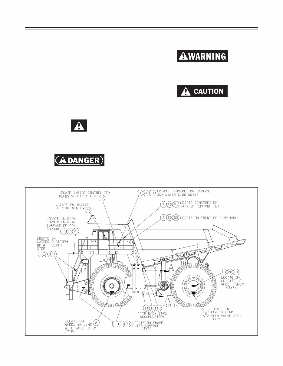
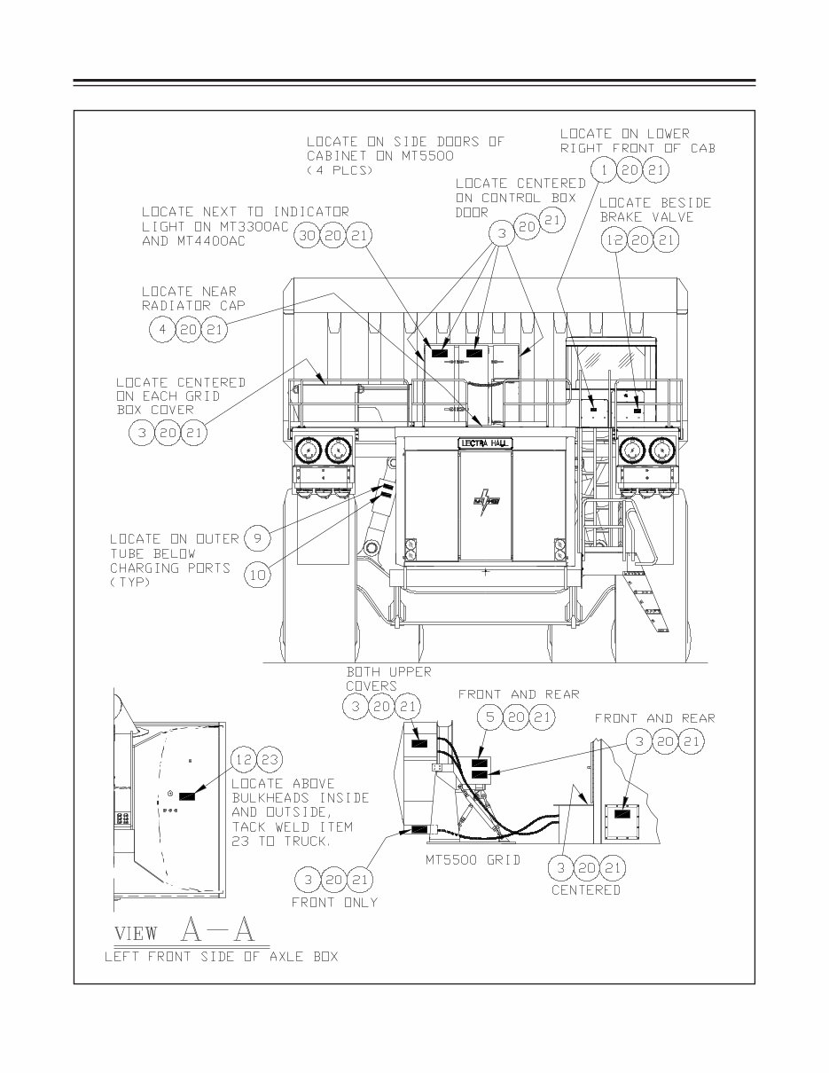
1 M1582 05/07/2004 TEREX|UNIT RIG SAFETY FIGURE 1 - HAZARD DECALS (A83678, SHEET 1 OF 5) SAFETY SAFETY Safety should be the primary concern of anyone work- ing on or around any vehicle. As safety-conscious indi- viduals, you should do nothing that will place yourself, other personnel or any equipment in a position of pos- sible injury or damage. DANGER, WARNING AND CAUTION EMBLEMS Safety and informational highlights used in this manual include: This symbol means your safety is involved! Read, un- derstand and follow all Danger, Warning, and Caution decals on your machine and instructions in this manual. The signal word DANGER indicates an imminent haz- ard situation which, if not avoided, will result in death or serious injury or death. The signal word WARNING indicates a potentially haz- ardous situation which, if not avoided, could result in death or serious injury. The signal word CAUTION indicates a potentially haz- ardous situation which, if not avoided, may result in minor or moderate injury. It may also be used to alert against unsafe practices. The signal words IMPORTANT and NOTE indicate op- erations, conditions, or specific information of sufficient importance to call for additional specific instructions or information. There are a number of such decals identifying areas of potential safety hazards. Refer to the illustrations for identification of those decals.
Discover the TEREX MT4400 & MT4400AC Workshop Service Repair Manual, a valuable resource for professional mechanics and DIY enthusiasts alike. This manual is available in electronic format, either as a .OVA file or a .PDF file, and is compatible with Windows and Mac operating systems.
To access the document, you will need the Adobe Acrobat Reader, which can be easily downloaded for free from the Adobe Acrobat website. The file size of this manual is 14 MB.
Containing comprehensive information, this manual covers the following engines:
65.0L 16-cylinder V16, turbocharged, air-cooled, DDC Series 4000 diesel engine
60.2L 16-cylinder V16, turbocharged, after-cooled, Cummins QSK60 Series diesel engine
The manual includes detailed information on various aspects, such as:
Main frame and structure
Loader and railing
Hood assembly
Steering column
Cab and heater
Wiper and washer
Fuel tank-dump body
Electrical system
Engine module
Air cleaner system
Exhaust system
Muffler system
Cooling system
Radiator system
Alternator and motor
Hydraulic system
Hydraulic filters
Hydraulic pump and tank
Dump system
Steering system
Superstructure system
Power supply system
Brake systems
Parking brake system
Shuttle valves
Pneumatic system
Front and rear axle
Tires and rims
Steering linkage
Suspension system
Rockwell system
Lubricating system
Rotary pump system
Engine oil system
Hubodometer system
Injectors system
Maintenance
Welding process
Component weights
Tightening torque
Electric drive system
Schematic diagram
This manual is designed to be easily printable, allowing users to extract specific pages as needed. It provides detailed illustrations, step-by-step written instructions, and necessary diagrams or pictures. Whether you are a DIY enthusiast or an experienced mechanic, this manual serves as the go-to resource for repair and service information. Many mechanics worldwide rely on this factory manual to effectively address vehicle issues. By utilizing this repair manual, you can ensure the proper functioning of your machine, thanks to its detailed guidance through each service, repair, and maintenance procedure.
Recently Viewed
5,521,897Happy Clients
2,594,462eManuals
1,120,453Trusted Sellers
15Years in Business
Price:
Actual Price:
TEREX MT4400 & MT4400AC Workshop Service Repair Manual