Komatsu HM300-2 Articulated Dump Truck Service & Repair Manual
What's Included?
Lifetime Access
Fast Download Speeds
Offline Viewing
Access Contents & Bookmarks
Full Search Facility
Print one or all pages of your manual
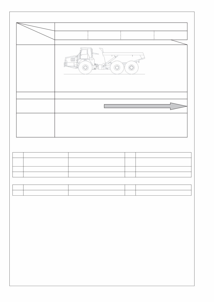
ARTICULATED DUMP TRUCK Field Assembly Instruction GEN00037-01 HM300 -2 SERIAL NUMBERS 2001 and up
Contents 1 Drawings of removed units ......................................................................... 1 2 Dimensions of removed units ..................................................................... 1 3 Assembly procedure, necessary equipments, and schedule .................. 2 4 Necessary tools and equipments ............................................................... 2 5 Assembly procedure No. ............................................................................. 3 0100 Positioning bare machine ................................................................... 3 0150 Installation of rear monitor.................................................................. 4 0200 Installing engine hood mirrors ............................................................ 5 0250 Installation of right and left mudguards .............................................. 6 0300 Adjusting N2 gas of front and rear suspensions ................................ 7 Attached sheet: Mirror adjustment procedure
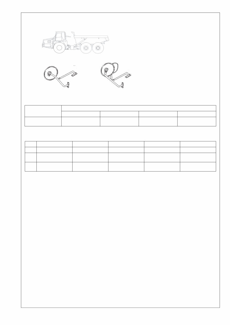
1 1 Drawings of removed units Specifications of HM300-2 completed truck 2 Dimensions of removed units 1. Bare machine 2. Engine hood mirror, L.H. 3. Engine hood mirror, R.H. Specifications Related items Weight (kg) Overall length (mm) Overall width (mm) Overall height (mm) Self-propelled travel 24,040 (Weight of machine) 10,440 2,900 3,520 (When empty) No. Unit name Weight (kg) Overall length (mm) Overall width (mm) Overall height (mm) 1 Bare machine 24,033 10,440 3,140 3,520 2 Engine hood mirror, L.H. 3 500 340 450 3 Engine hood mirror, R.H. 4 570 300 450
2 3 Assembly procedure, necessary equipments, and schedule 4 Necessary tools and equipments (1) Necessary tools (2) Necessary equipments 1 Day Hour 1st day 2 3 4 Assembly unit Assembly procedure No. No.0100 - 0300 Number of workers Remarks Meeting before work Unloading Starting assembly Completion of assembly 2 (4) Installation of right and left mudguards (5) Adjusting N2 gas of front and rear suspensions (6) Inspection (1) Positioning bare machine (2) Installation of rear monitor (3) Installing engine hood mirrors No. Tool name Specifications Q'ty Remarks 1 Ring wrench 19 mm 1 For installing hood mirror and front cover 2 Paint spray can Clear 1 For touching up bolt head 3 Suspension gas pouring tool 7926-10-1000 1 For adjusting suspension pressure No. Equipment name Specifications Q'ty Remarks 1 Stepladder (Work stand) 4 steps (About 1.5 m) 1 For work
3 1. Positioning bare machine 1. Lower the bare machine from the trailer and position it on the flat ground. Assembly procedure No. Positioning bare machine No.0100 Precautions Necessary tools Necessary equipment Name Q’ty Name Q’ty Others
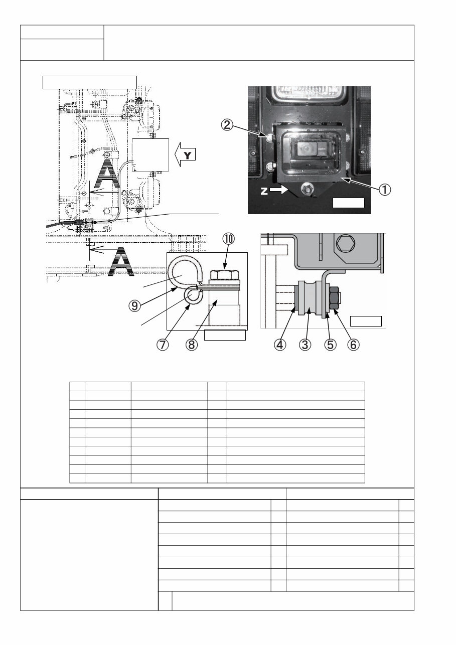
4 1. Install the rear monitor assembly as shown above. 2. Connect the rear monitor cable. Assembly procedure No. Installation of rear monitor No.0150 Part No. Part name Q'ty State of parts (Parts list No.) (1) 561-86-8310A REAR MONITOR ASS'Y 1 Separately packed (M32-06-050) (2) 01024-80816 BOLT 4 Temporarily installed to rear lamp bracket (3) 08522-10000 CUSHION 1 Temporarily installed to rear lamp bracket (4) 01643-31032 WASHER 1 Temporarily installed to rear lamp bracket (5) 203-54-56970 WASEHR 1 Temporarily installed to rear lamp bracket (6) 01582-01008 NUT 1 Temporarily installed to rear lamp bracket (7) 04434-50810 CLIP 1 Temporarily installed to rear lamp bracket (8) 424-54-14380 COLLAR 1 Temporarily installed to rear lamp bracket (9) 04434-51410 CLIP 1 Temporarily installed to rear lamp bracket (10) 01024-81030 BOLT 1 Temporarily installed to rear lamp bracket Precautions Necessary tools Necessary equipment Name Q’ty Name Q’ty Others Rear camera seen from above To be connected. View Y Rear frame wiring harness Rear monitor wiring harness Section A-A View Z
5 1. Installing engine hood mirrors 1. Remove the bolts and washers installed to the engine hood temporarily. 2. Take the engine hood mirrors out of the cab and install them to the engine hood. 3. Adjust the angle of the mirror. a To adjust, see Operation and Maintenance Manual. Assembly procedure No. Installing engine hood mirrors No.0200 Precautions Necessary tools Necessary equipment Name Q’ty Name Q’ty Ring wrench (19 mm) 1 Stepladder (Work stand) 1 Others Installed to engine hood temporarily Installed to engine hood temporarily Installed to engine hood temporarily Engine Hood 1 3 3 2 3 3 Part No. Part name Q'ty State of parts (1) 56D-54-21510 STAY, L.H. 1 Mounted in cab (2) 56D-54-21520 STAY, R.H. 1 (3) 01024-81225 BOLT 8 Installed to engine hood temporarily
6 1. Install mudguards to the right and left fenders. 1. Remove the bolts and plates installed temporarily to the fenders. 2. Install mudguards mounted in the cab to the fenders. Assembly procedure No. Installation of right and left mudguards No.0250 Part No. Part name Q'ty State of parts (1) 56D-54-22950 GUARD, L.H. 1 Mounted in cab (2) 56D-54-22960 GUARD, R.H. 1 Mounted in cab (3) 56D-54-22970 PLATE 2 Temporarily installed to fender (4) 01024-81025 BOLT, SEMS 4 Temporarily installed to fender Precautions Necessary tools Necessary equipment Name Q’ty Name Q’ty Ring wrench (19 mm) 1 Stepladder (Work stand) 1 Others
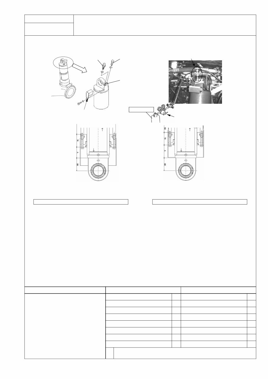
7 1. Adjusting N2 gas of front and rear suspensions Adjust the quantity of N2 gas (front and rear, 4 places). 1. Loosen the air bleeding valves of the right and left front suspension cylinders and bleed air thoroughly. (Check that air does not come out any more (and only oil flows out) and tighten the valves again. Tightening torque: 39.2 – 49.0 Nm {4 – 5 kgm}) 2. Check that the valves are closed and install the suspension gas pouring tool to the gas cylinder. 3. Connect the hoses of the suspension gas pouring tool to the nitrogen gas pouring valves. (Since there are 2 hoses, connect them to the right and left suspension cylinders and pour the nitrogen gas simultaneously so that pressure will be applied to both cylinders even- ly.) 4. Open the valve of the suspension gas pouring tool gradually. 5. When the suspension cylinders rise to the specified level shown above, close the valve. (Pour the gas to the front suspension cylinders until they rise to the level indicated by the decalcomania. Pour the gas to the rear suspension cylinders until they rise to the level shown in the above figure.) 6. Remove the hoses from the nitrogen gas pouring valves and move the machine forward and in reverse to fit the suspension cylinders, and then stop without applying the brake. (Finally, stop the machine without applying the brake to prevent an uneven load caused by braking.) 7. Apply the parking brake and check the length of the suspension cylinders. 8. If the length of the suspension cylinders is out of the standard range, repeat steps 3 - 7. (Usually, adjustment is completed by repeating those steps 3 - 4 times.) Assembly procedure No. Adjusting N2 gas of front and rear suspensions No.0300 Dimension A (Front side) Dimension A (Rear side) When cylinder is retracted fully: MIN (83 ± 1 mm) When cylinder is retracted fully: MIN (31 ± 1 mm) Specified quantity of filled oil: OIL 113 ± 3 mm Specified quantity of filled oil: OIL 51 ± 3 mm When empty: EMPTY (163 ± 5 mm) When empty: EMPTY (101 ± 5 mm) When cylinder is extracted fully: MAX (196 ± 1 mm) When cylinder is extracted fully: MAX (121 ± 1 mm) Precautions Necessary tools Necessary equipment 1. Bleed air from the cylinders. 2. Pour nitrogen gas in the right and left suspension cylinders simultaneously. 3. Do not extend the suspension cylinders to the stroke end. 4. After moving the machine forward and in reverse, stop it without applying the brake. 5. Do not steer the machine before finishing this adjustment. (If it is steered, the piping may be broken.) Name Q’ty Name Q’ty Suspension gas pouring tool 1 (7926-10-1000) Others Front suspension Before adjusting suspension gas, remove the cover. After adjusting install it. Air bleeding valve Air bleeding hole N2 gas pouring valve Installing position of suspension gas pouring tool N2 gas cylinder Suspension gas pouring tool (7826-10-1000) Chassis side Front suspension cylinder Rear suspension cylinder Axle side Chassis side Axle side
This is a comprehensive Service Shop Repair Manual for the Komatsu HM300-2 Articulated Dump Truck. It contains detailed information on maintenance, assembly, disassembly, and servicing of the Komatsu HM300-2 Articulated Dump Truck.
MACHINE MODEL SERIAL NUMBER
HM300-2 - 2001 and up
CONTENTS INCLUDE:
00 INDEX AND FOREWORD
01 SPECIFICATION
10 STRUCTURE, FUNCTION AND MAINTENANCE STANDARD
20 STANDARD VALUE TABLE
30 TESTING AND ADJUSTING
40 TROUBLESHOOTING
50 DISASSEMBLY AND ASSEMBLY
90 DIAGRAMS AND DRAWINGS
Model Specification: Komatsu HM300-2 Articulated Dump Truck
Language: English
File Format: .PDF
Total Pages: 1360
Requirements: Adobe Reader
ZOOM IN/OUT: YES
Printable: YES
Compatible: All Versions of Windows & Mac
This manual contains specifications, diagrams, actual real photo illustrations, and detailed schemes that provide complete step-by-step operations for repair, servicing, technical maintenance, and troubleshooting procedures for your machine. It offers all the information needed to perform repairs and maintenance without needing to visit a service center.
After your payment is confirmed, the manual is available instantly for viewing, printing, and use. With numerous clear pictures and diagrams, it is convenient to bring along to your garage or workshop. The easy-to-follow instructions make it simple for users of all skill levels to save money by handling their own repairs.
Recently Viewed
5,521,897Happy Clients
2,594,462eManuals
1,120,453Trusted Sellers
15Years in Business
Price:
Actual Price:
Komatsu HM300-2 Articulated Dump Truck Service & Repair Manual