



Atlas Copco
Maintenance instructions
Hydraulic Rock drills
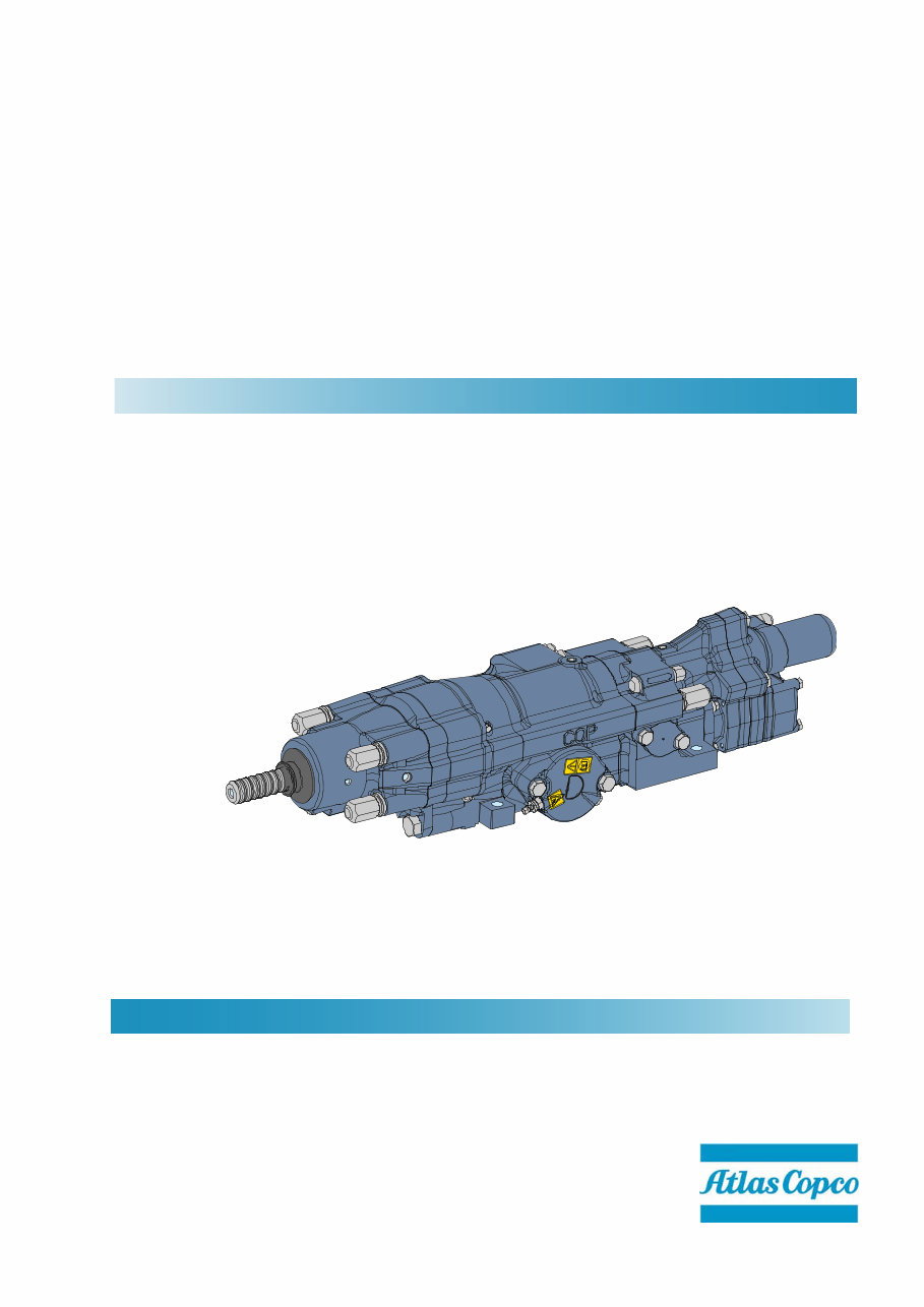
COP 1838HD
No. 9852 2462 01
Atlas Copco Rock Drills AB
Örebro, Sweden
© Atlas Copco Rock Drills AB, 2010. All rights reserved

© Copyright 2010, Atlas Copco Rock Drills AB, Sweden
Any unauthorised use or copying of the contents or any part thereof is prohibited.
This applies in particular to trademarks, model denominations, part numbers and draw-
ings.
Atlas Copco Rock Drills AB
SE-70191 Örebro, Sweden
www.atlascopco.com

Contents
3
Contents
1. General............................................................................................................................. 5
Environment ....................................................................................................................................5
Safety regulations ............................................................................................................................5
Warning boxes............................................................................................................................. 5
The following general safety rules must be observed ................................................................. 6
2. Service interval ............................................................................................................... 9
Before starting a new or newly overhauled rock drill .......................................................................9
After each shift when using a new or newly overhauled rock drill ...................................................9
Before each shift ..............................................................................................................................9
After every 40th percussion hour .....................................................................................................9
Every 400th percussion-hour: ..........................................................................................................9
3. Hose connections ......................................................................................................... 10
Connecting the hoses ....................................................................................................................10
4. Tightening torques ....................................................................................................... 11
Adjusting the side bolts ..................................................................................................................12
Tightening the side bolts............................................................................................................ 12
Retightening the side bolts ........................................................................................................ 12
5. Accumulators ................................................................................................................ 13
Safety labels ..................................................................................................................................13
Location and meaning ............................................................................................................... 13
Charging the accumulators ............................................................................................................13
Checking the accumulators in the event of hose vibration ............................................................13
Damper accumulatorand intake accumulator ........................................................................... 13
Replacing intake and damper accumulator ...................................................................................14
Dismantling ................................................................................................................................ 14
Assembly ................................................................................................................................... 14
Replacing the return accumulator ..................................................................................................15
Dismantling ................................................................................................................................ 15
Assembly ................................................................................................................................... 15
6. Hydraulic motor ............................................................................................................ 16
Replacing the hydraulic motor .......................................................................................................16
Dismantling ................................................................................................................................ 16
Assembly ................................................................................................................................... 16
7. Filling with lubricating oil and bleeding the system.................................................. 17
8. Settings .......................................................................................................................... 18
Setting of ECL lubricating system ..................................................................................................18
Setting the damper pressure .........................................................................................................18
9. Removing the front head.............................................................................................. 19
10. Checking the front head ............................................................................................... 20
11. Mounting the front head ............................................................................................... 21
12. Slinging, weights, storage and hose length ............................................................... 22
Slinging ..........................................................................................................................................22
Rock drill weights ...........................................................................................................................22
Long-term storage .........................................................................................................................22
13. Lubrication .................................................................................................................... 23
Lubrication of gear .........................................................................................................................23
14. Hydraulic and lubricant recommendations ................................................................ 24
Hydraulic fluid ................................................................................................................................24
Pneumatic tool oil ..........................................................................................................................25
Grease ...........................................................................................................................................25

Contents
4

General 1
5
1. General
This instruction is intended as a guide when
performing maintenance on your rock drill.
Environment
Safety regulations
The Safety chapter contains important information
for the prevention of accidents.
Warning boxes
The manual contains warnings.
Warnings are preceded by a heading (Danger,
Warning and Caution).
Environmental regulations
Care for the environment!
Leaking hydraulic couplings and grease are
hazardous to the environment.
Changing oils, hydraulic hoses and various
types of filter can be hazardous to the environ-
ment.
Always collect oil residues, oil spillage, oily
waste and residues and spilt grease. Deal with
according to local provisions.
Use biodegradable hydraulic and lubricating
oils where possible.
Warning boxes
Danger
Indicates an imminent risk of serious or fatal
injury if the warning is not heeded.
Warning
Indicates hazards or hazardous procedures
which could result in serious or fatal injury if
the warning is not heeded.
Caution
Indicates hazards or hazardous procedures
which could result in personal injury or
damage to property if the warning is not
heeded.

General 1
6
The following general safety rules must be
observed
Important!
Read through the maintenance instructions
carefully before starting maintenance work.
Follow the instructions given and local regula-
tions.
Do not use or intervene in the rock drill unless
you have been trained to do so.
Never attempt to carry out maintenance while
the rock drill is in operation.
Ensure that the hydraulic, water and air systems
are depressurised and that the electrical system
is de-energised prior to removing the rock drill
or starting work on the system.
Use approved lifting devices when handling the
rock drill. Avoid lifting heavy weights yourself.
To prevent injury during service and mainte-
nance, all components that could possibly move
or drop must be supported safely on blocks or
trestles, or secured by means of adequately
dimensioned slings.
Check that the hoses used are of the right
quality, and that all hose connections are in
good condition and properly tightened. Hoses
that loosen could cause serious injury.
Use only Atlas Copco original parts. Any
damage or malfunction caused by the use of
non-original Atlas Copco parts is not covered by
warranty or product liability.
Important!
Make sure that the rock drill has been main-
tained in accordance with the applicable instruc-
tions.
Before moving the rig and rock drill or starting to
drill, make sure that there are no personnel in
the immediate vicinity of the drill rig.
Checks and adjustments that are necessary
when the rock drill is in operation must be
carried out by at least two persons. One person
must then be present at the operating station
and have a good view of the work.
Always wear a helmet and earmuffs when dril-
ling. Follow local regulations
Make sure that the place of work is well venti-
lated.
Make sure that the safety labels are fitted, clean
and fully legible.
Particular attention must be paid to all warnings
in the manual.
Exercise caution when jointing drill rods and
with drill bit handling. Watch your fingers!
Make sure that clothes do not come too close to
rotating machine parts.
Negligence could cause serious injury.

General 1
7
Important!
A mining machine has many components and
implements that are controlled by a hydraulic
system, either directly or indirectly. Before
working on or inspecting any part of a mining
machine, it is important that the individual
knows how the components move and are
controlled by the hydraulic system components
including the respective control circuits.
Before working on or inspecting any compo-
nent, it must be physically constrained from any
movement that could cause injury to the worker.
The worker must be alert to not placing any part
of his/her body where movement of a compo-
nent could cause injury, unless that component
is physically constrained from movement, if the
hydraulic system fails, is disconnected, or is
signaled to cause movement.
It must also be recognized that there are occa-
sions where component and or vehicle move-
ment may react to the release of potential
energy. Where applicable it must be confirmed
that all measures are employed to ensure that
any and all sources of potential energy are rele-
ased and/ or physically restrained.
It is also the responsibility of those involved to
insure that all local, state and federal safety
regulations are followed, prior to, and during
any work or inspection.

General 1
8

Service interval 2
9
2. Service interval
Part numbers for the repair kits are in the rock drill’s spare parts catalogue
Before starting a new or newly overhauled rock drill
Chapter
• Connect up the hoses ..........................................................................................................................3
• Charge the accumulators .....................................................................................................................5
• Select a suitable hydraulic oil and lubricant........................................................................................14
• Fill the lubricating system with oil .........................................................................................................7
• Adjust and set the lubricating system ...................................................................................................8
• Set the damper pressure ......................................................................................................................8
After each shift when using a new or newly overhauled rock drill
• Tighten all threaded unions ..................................................................................................................4
Before each shift
• Check that air and lubricating oil escape in between the shank adapter and front guide
and out of the hole in the front head...................................................................................................10
• Check that the drill rig’s damper pressure gauge is showing normal values.
Check that the drill rig’s damper pressure gauge is showing normal values. In the event of deviation,
adjust the damper pressure..................................................................................................................8
• Check that the shank adapter threads are not damaged ...................................................................10
• Keep an eye on the hydraulic hoses. If they vibrate too much,
check the accumulators ........................................................................................................................5
• Check that the machine does not leak. If the flushing medium leaks out of the flushing head,
replace seals and O-rings...................................................................................................................10
• When replacing the shank adapter or removing the front head,
check the internal components including piston, driver and the visible parts of the rotation chuck bushing
............................................................................................................................................................10
• In the event of oil leakage from the front head: close percussion and only activate the damper
in order to determine if the leakage is coming from the percussion or damper . .................................10
After every 40th percussion hour
• Grease the gear .................................................................................................................................13
• Tighten all threaded unions ..................................................................................................................4
• Check the safety labels on the accumulators. Replace them if they are damaged or illegible .............5
• Check the accumulators .......................................................................................................................5
Every 400th percussion-hour:
• Dismantle the rock drill from the drill rig. Transport the rock drill to
an appropriate workshop for servicing................................................................................................12
Important!
Always function test the rock drill after service.
Hose connections 3
10
3. Hose connections
Connecting the hoses
• Clean the rock drill’s hose connections before
undoing the protective caps.
• Never remove a protective cap until the hose is
ready to be connected.
• Always store the rock drill with all hose connec-
tions plugged. Use suitable protective caps, and
make sure that they are clean.
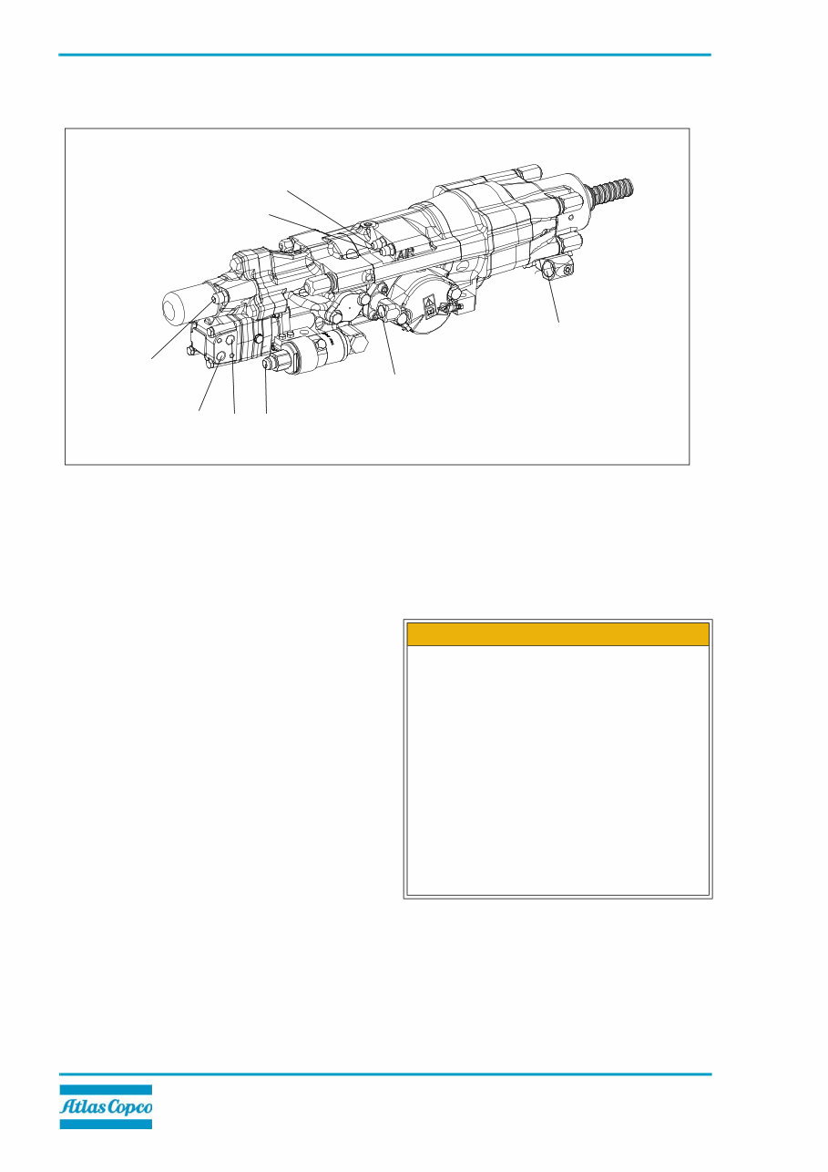
1
2
3 4
5
6
7
8
1250 0240 34
1. Drainage
2. Rotation left
3. Rotation right
4. Percussion return
5. Inlet impact mechanism
6. Flushing air/water
7. Lubricating air
8. Damper, intake
Caution!
Never attempt maintenance or intervene in the
rock drill, connections or hoses while the
hydraulic, lubrication or flushing systems are
pressurised. Air or oil can spray out at high
pressure and high temperature. There is a risk
of serious injury to the eyes and skin.
Pressure hoses with an internal diameter of 19
mm (3/4”) or greater are of the quality SAE 100
R9R (high-pressure hose with four layers of
steel reinforcement). See the rock drill’s spare
parts list. For reasons of safety, under no
circumstance may these hoses be replaced
with hoses of a lower quality. There is a risk of
injury if these instructions are not observed!
You're Reading a Preview
What's Included?
 Lifetime Access
Fast Download Speeds
Online & Offline Access
Access PDF Contents & Bookmarks
Full Search Facility
Print one or all pages of your manual
$31.99
Atlas copco 1838 rock drill maintenance instructions
Viewed 73 Times Today

What's Included?
Lifetime Access
Fast Download Speeds
Online & Offline Access
Access PDF Contents & Bookmarks
Full Search Facility
Print one or all pages of your manual
$31.99

Secure transaction
What's Included?
Lifetime Access
Fast Download Speeds
Online & Offline Access
Access PDF Contents & Bookmarks
Full Search Facility
Print one or all pages of your manual
Description
These maintenance instructions cover the following models:
- COP 1838ME
- COP 1838MEX
- COP 1838HE
- COP 1838HEX
- COP 1838LE
- COP 1838HF


