

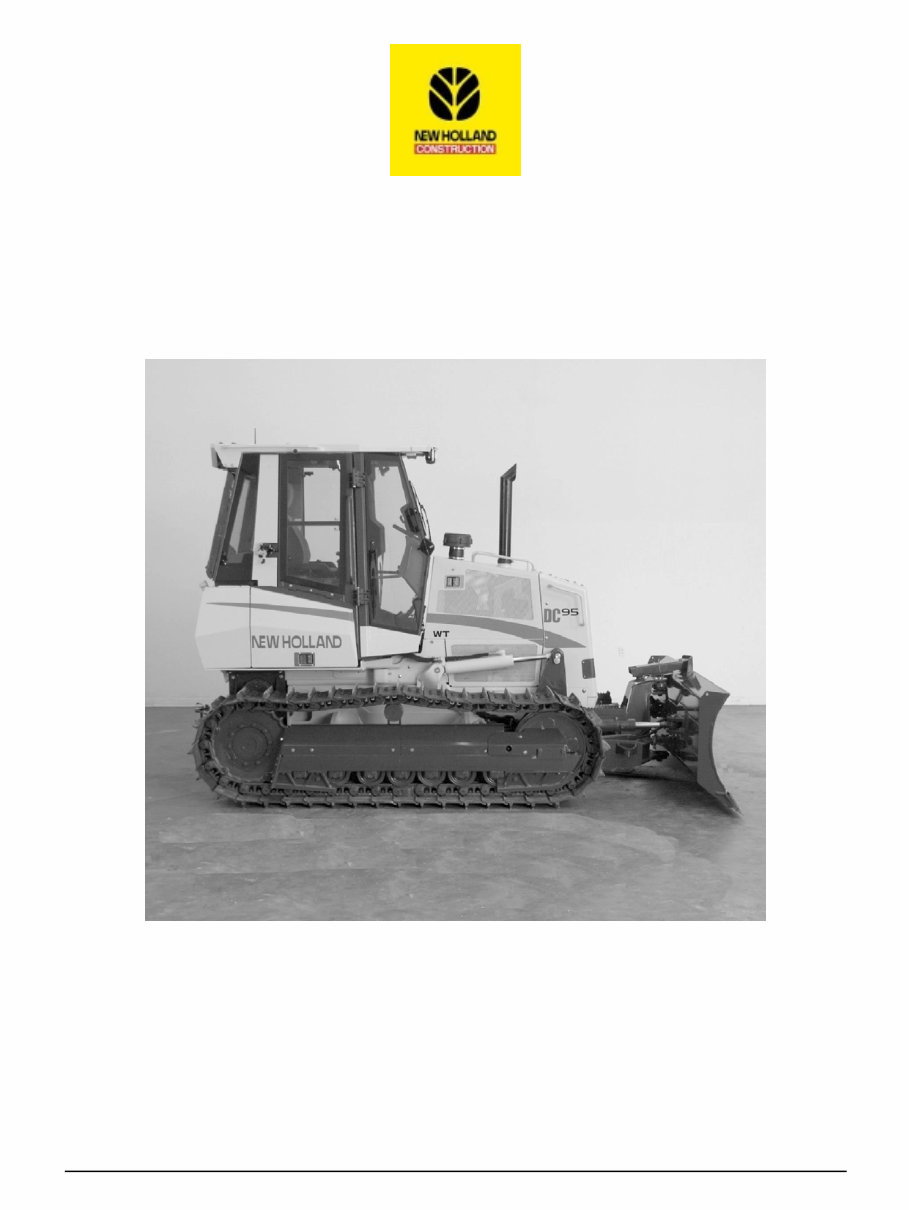
REPAIR MANUAL
DC75
DC85
DC95
6-76640 1 15/06/2004

Contents
INTRODUCTION
DISTRIBUTION SYSTEMS A
POWER PRODUCTION B
POWER TRAIN C
TRAVELLING D
BODY AND STRUCTURE E
TOOL POSITIONING G
WORKING ARM H
TOOLS AND COUPLERS J
Engine Service Manual form number 6-49731
6-76640 1 15/06/2004
Issued June, 2004 • Bur
Copyright © 2004 CNH America LLC. All Rights Reserved.

INTRODUCTION
6-76640 1 15/06/2004
1

Contents
INTRODUCTION
Basic instructions ( - A.90.A.05)
DC75, DC85, DC95
3
Hydraulic contamination ( - A.92.A.60)
DC75, DC85, DC95
7
General specification ( - A.92.A.10)
DC75, DC85, DC95
8
Conversion factors ( - A.92.A.21)
DC75, DC85, DC95
13
6-76640 1 15/06/2004
2

INTRODUCTION
Basic instructions ( - A.90.A.05)
DC75, DC85, DC95
Technical Information
This manual has been produced by a new technical information system. This new system is designed to deliver
technical information electronically through CDROM and in paper manuals. A coding system called ICE has been
developed to link the technical information to other Product Support functions e.g. Warranty.
Technical information is written to support the maintenance and service of the functions or systems on a customers
machine. When a customer has a concern on his machine it is usually because a function or system on his machine
is not working at all, is not working efficiently, or is not responding correctly to his commands. When you refer to the
technical information in this manual to resolve that customers concern, you will find all the information classified
using the new ICE coding, according to the functions or systems on that machine. Once you have located the
technical information for that function or system then you will find all the mechanical, electrical or hydraulic devices,
components, assemblies and sub-assemblies for that function or system. You will also find all the types of information
that have been written for that function or system, the technical data (specifications), the functional data (how it
works), the diagnostic data (fault codes and troubleshooting) and the service data (remove, install adjust, etc.).
By integrating this new ICE coding into technical information , you will be able to search and retrieve just the right
piece of technical information you need to resolve that customers concern on his machine. This is made possible by
attaching 3 categories to each piece of technical information during the authoring process.
The first category is the Location, the second category is the Information Type and the third category is the Product:
•
LOCATION - is the component or function on the machine, that the piece of technical information is going to
describe e.g. Fuel tank.
•
INFORMATION TYPE - is the piece of technical information that has been written for a particular component or
function on the machine e.g. Capacity would be a type of Technical Data that would describe the amount
of fuel held by the Fuel tank.
•
PRODUCT - is the model that the piece of technical information is written for.
Every piece of technical information will have those 3 categories attached to it. You will be able to use any
combination of those categories to find the right piece of technical information you need to resolve that customers
concern on his machine.
That information could be:
•
the description of how to remove the cylinder head
•
a table of specifications for a hydraulic pump
•
a fault code
•
a troubleshooting table
•
a special tool
How to Use this Manual
This manual is divided into Sections. Each Section is then divided into Chapters. Contents pages are included at
the beginning of the manual, then inside every Section and inside every Chapter. An alphabetical Index is included
at the end of a Chapter. Page number references are included for every piece of technical information listed in
the Chapter Contents or Chapter Index.
Each Chapter is divided into four Information types:
•
Technical Data (specifications) for all the mechanical, electrical or hydraulic devices, components and,
assemblies.
•
Functional Data (how it works) for all the mechanical, electrical or hydraulic devices, components and
assemblies.
6-76640 1 15/06/2004
3
INTRODUCTION
•
Diagnostic Data (fault codes, electrical and hydraulic troubleshooting) for all the mechanical, electrical or
hydraulic devices, components and assemblies.
•
Service data (remove disassembly, assemble, install) for all the mechanical, electrical or hydraulic devices,
components and assemblies.
Sections
Sections are grouped according to the main functions or a systems on the machine. Each Section is identified by
a letter A, B, C etc. The amount of Sections included in the manual will depend on the type and function of the
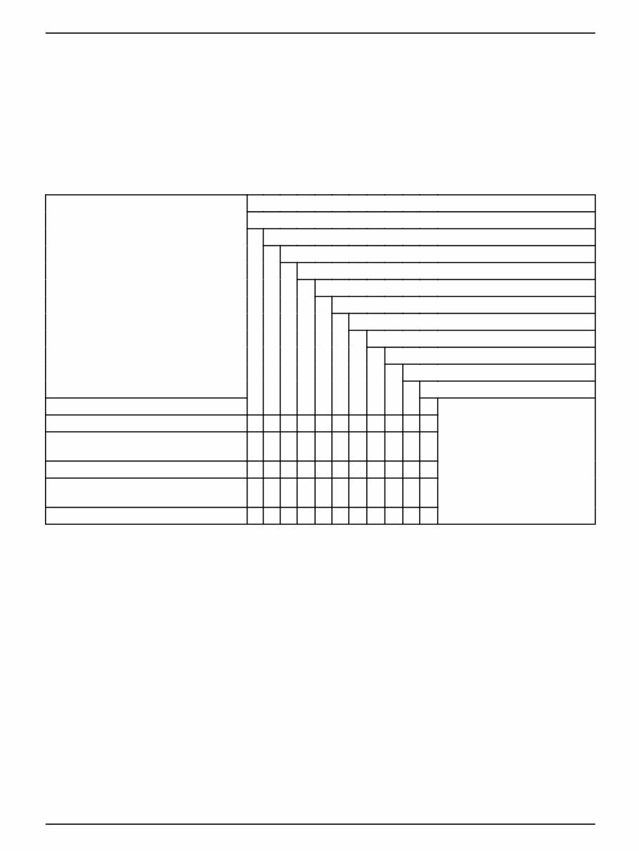
machine that the manual is written for. Each Section has a Contents page listed in alphabetic/numeric order. This
table illustrates which Sections could be included in a manual for a particular product.
SECTION
A - Distribution Systems
B - Power Production
C - Power Train
D - Travelling
E - Body and Structure
F - Frame Positioning
G - Tool Positioning
H - Working Arm
J - Tools and Couplers
K - Crop Processing
L - Field Processing
PRODUCT
Tractors X X X X X X X X
Vehicles with working arms: backhoes,
excavators, skid steers, .....
X X X X X X X X X
Combines, forage harvesters, balers, .... X X X X X X X X X X
Seeding, planting, floating, spraying
equipment, ....
X X X X X X X X X
Mounted equipment and tools, ..... X X X X
Chapters
Each Chapter is identified by a letter and number combination e.g. Engine B.10.A The first letter is identical to the
Section letter i.e. Chapter B.10 is inside Section B, Power Production.
CONTENTS
The Chapter Contents lists all the technical data (specifications), functional data (how it works), service data
(remove, install adjust, etc..) and diagnostic data (fault codes and troubleshooting) that have been written in that
Chapter for that function or system on the machine.
Contents
POWER PRODUCTION
ENGINE _ 10.A
TECHNICAL DATA
ENGINE - General specification (B.10.A - D.40.A.10) 3
FUNCTIONAL DATA
ENGINE - Dynamic description (B.10.A - C.30.A.10) 4
SERVICE
ENGINE - Remove (B.10.A - F.10.A.10) 5
6-76640 1 15/06/2004
4
INTRODUCTION
DIAGNOSTIC
ENGINE - Troubleshooting (B.10.A - G.40.A.10) 6
INDEX
The Chapter Index lists in alphabetical order all the types of information (called Information Units) that have been
written in that Chapter for that function or system on the machine.
Index
POWER PRODUCTION - B
ENGINE
ENGINE - Dynamic description (B.10.A - C.30.A.10) 4
ENGINE - General specification (B.10.A - D.40.A.10) 3
ENGINE - Remove (B.10.A - F.10.A.10) 5
ENGINE - Troubleshooting (B.10.A - G.40.A.10) 6
Information Units and Information Search
Each chapter is composed of information units. Each information unit has the ICE code shown in parentheses which
indicates the function and the type of information written in that information unit. Each information unit has a page
reference within that Chapter. The information units provide a quick and easy way to find just the right piece of
technical information you are looking for.
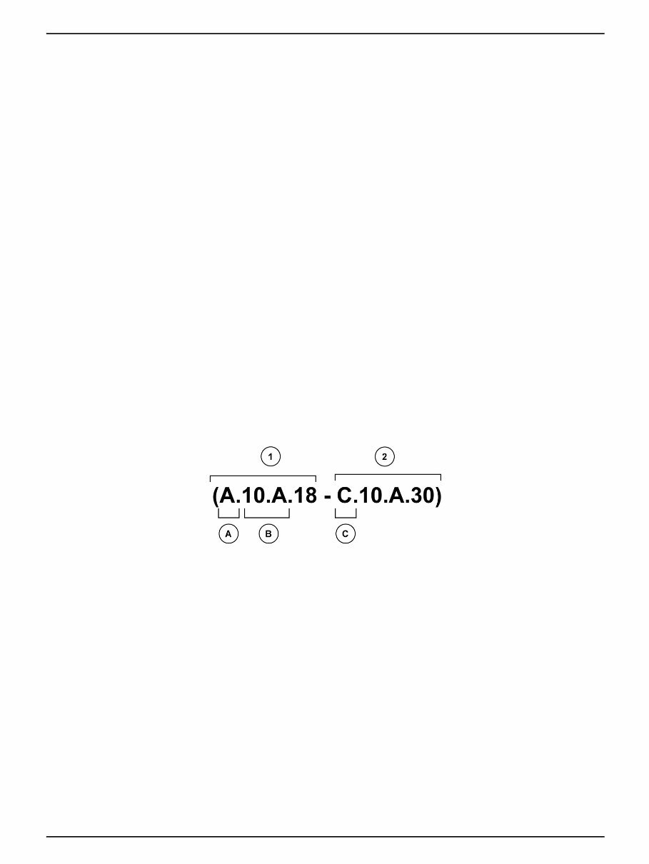
example information unit Stack valve - Sectional View (A.10.A.18 - C.10.A.30)
Information Unit ICE code A 10.A 18 C 10.A.30
ICE code classification Distribution
systems
Primary
hydraulic
power
Stack valve Functional
data
Sectional view
CRIL03J033E01 1
Navigate to the correct information unit you are searching for by identifying the function and information type
from the ICE code.
•
(1) Function and (2) Information type.
•
(A) corresponds to the sections of the repair manual.
(B) corresponds to the chapters of the repair manual.
(C) corresponds to the type of information listed in the chapter contents, Technical data, Functional Data,
Diagnostic or Service.
(A) and (B) are also shown in the page numbering on the page footer.
THE REST OF THE CODING IS NOT LISTED IN ALPHA-NUMERIC ORDER IN THIS MANUAL.
•
You will find a table of contents at the beginning and end of each section and chapter.
You will find an alphabetical index at the end of each chapter.
•
By referring to (A), (B) and (C) of the coding, you can follow the contents or index (page numbers) and quickly
find the information you are looking for.
6-76640 1 15/06/2004
5

INTRODUCTION
Page Header and Footer
The page header will contain the following references:
•
Section and Chapter description
The page footer will contain the following references:
•
Publication number for that Manual, Section or Chapter.
•
Version reference for that publication.
•
Publication date
•
Section, chapter and page reference e.g. A.10.A / 9
6-76640 1 15/06/2004
6

INTRODUCTION
Hydraulic contamination ( - A.92.A.60)
DC75, DC85, DC95
Contamination in the hydraulic system is a major cause of the malfunction of hydraulic components. Contamination
is any foreign material in the hydraulic oil. Contamination can enter the hydraulic system in several ways.
(A) When you drain the oil or disconnect any line.
(B) When you disassemble a component.
(C) From normal wear of the hydraulic components.
(D) From damaged or worn seals.
(E) From a damaged component in the hydraulic system.
All hydraulic systems operate with some contamination. The design of the components in this hydraulic system
permits efficient operation with a small amount of contamination. An increase in this amount of contamination can
cause problems in the hydraulic system. The following list includes some of these problems.
(A) Cylinder rod seals leak.
(B) Control valve spools do not return to neutral.
(C) Movement of control valve spools is difficult.
(D) Hydraulic oil becomes too hot.
(E) Pump gears, housing, and other parts wear rapidly.
(F) Relief valves or check valves held open by dirt.
(G) Quick failure of components that have been repaired.
(H) Cycle times are slow; machine does not have enough power.
If your machine has any of these problems, check the hydraulic oil for contamination. There are two types of
contamination, microscopic and visible.
Microscopic contamination occurs when very fine particles of foreign material are in suspension in the hydraulic
oil. These particles are too small to see or feel. Microscopic contamination can be found by identification of the
following problems or by testing in a laboratory. Examples of the problems:
(A) Cylinder rod seal leak.
(B) Control valve spools do not return to NEUTRAL.
(C) The hydraulic system has a high operating temperature.
Visible contamination is foreign material that can be found by sight, touch, or odor. Visible contamination can cause
a sudden failure of components. Examples of visible contamination:
(A) Particles of metal or dirt in the oil.
(B) Air in the oil.
(C) The oil is dark and thick.
(D)The oil has an odor of burned oil.
(E) Water in the oil.
If you find contamination, use a Portable Filter to clean the hydraulic system.
6-76640 1 15/06/2004
7
INTRODUCTION
General specification ( - A.92.A.10)
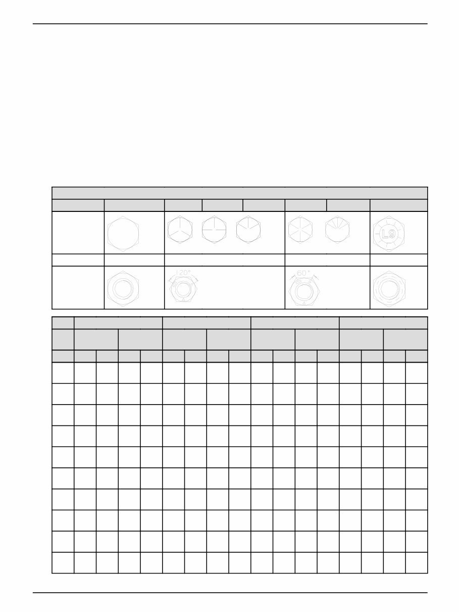
BOLT TORQUE INFORMATION
DECIMAL HARDWARE
1. Fasteners should be replaced with the same or higher grade. If higher grade fasteners are used, these
should only be tightened to the strength of the original.
2. Make sure the fasteners threads are clean and that thread engagement is started. This will prevent them from
failing when being tightened.
3. Tighten plastic insert or crimped steel-type lock nuts to approximately 50 % of the dry torque, applied to the
nut, not to the bolt head. Tighten toothed or serrated-type lock nuts to the full torque value.
4. The L9 (Alloy) fasteners torque values are for a bolt, nut, and two washers. When using L9 (Alloy) fasteners,
do not use the values in this table for tapped holes.
GRADE
1 or 2 5 5.1 5.2 8 8.2 L9 (Alloy)
SAE
Markings for
Bolts and
Cap Screws
2 5 8 L9 (Alloy)
SAE
Markings for
Hex Nuts
GRADE 2 * GRADE 5, 5.1 or 5.2 GRADE 8 or 8.2 GRADE L9 (Alloy)
Dry **
Lubri-
cated ** Dry**
Lubri-
cated ** Dry**
Lubri-
cated ** Head Nut
SIZE Nm lb/ft Nm lb/ft Nm lb/ft Nm lb/ft Nm lb/ft Nm lb/ft Nm lb/ft Nm lb/ft
1/4
UNF
7.5 5.5 5.7 4.2 10.8 8 8.5 6.3 16.3 12 12.2 9 13.6 10 14.9 11
1/4
UNC
8.5 6.3 6.4 4.7 13.6 10 9.8 7.2 19 14 13.6 10 16.3 12 17.6 13
5/16
UNF
15 11 11 8 23 17 18 13 33 24 24 18 26 19 28 21
5/16
UNC
16 12 12 9 26 19 19 14 37 27 27 20 27 20 31 23
3/8
UNF
27 20 20 15 41 30 31 23 61 45 47 35 41 30 45 33
3/8
UNC
31 23 23 17 47 35 34 25 68 50 47 35 47 35 52 38
7/16
UNF
43 32 33 24 68 50 47 35 95 70 68 50 75 55 81 60
7/16
UNC
49 36 37 27 75 55 54 40 108 80 81 60 81 60 88 65
1/2
UNF
68 50 47 35 102 75 75 55 149 110 108 80 115 85 129 95
1/2
UNC
75 55 54 40 115 85 88 65 163 120 122 90 129 95 142 105
6-76640 1 15/06/2004
8
You're Reading a Preview
What's Included?
 Lifetime Access
Fast Download Speeds
Online & Offline Access
Access PDF Contents & Bookmarks
Full Search Facility
Print one or all pages of your manual
$240.99
New Holland CE DC75, DC85, DC95 Service Manual
Viewed 79 Times Today

What's Included?
Lifetime Access
Fast Download Speeds
Online & Offline Access
Access PDF Contents & Bookmarks
Full Search Facility
Print one or all pages of your manual
$240.99

Secure transaction
What's Included?
Lifetime Access
Fast Download Speeds
Online & Offline Access
Access PDF Contents & Bookmarks
Full Search Facility
Print one or all pages of your manual
Description
- The New Holland CE DC75, DC85, DC95 Dozers Repair Manual is an essential guide for individuals working with these dozers, offering detailed instructions for removal, installation, disassembly, and assembly of various components.
- Whether you are a professional technician or a do-it-yourself enthusiast, this manual is designed to assist you in completing the job accurately.
- It includes step-by-step instructions, an electrical wiring diagram, and hydraulic schematic, which are valuable for troubleshooting electrical or hydraulic issues.
- The manual also provides diagnostic information to help accurately identify and resolve any issues with the dozer.
- Additionally, it contains specifications and torque values for various components, ensuring correct installation and assembly to prevent potential damage or malfunctions.
- The New Holland CE DC75, DC85, DC95 Dozers Repair Manual is a comprehensive resource for maintaining, repairing, and diagnosing these dozers.


