D31EX, PX-21 D37EX, PX-21 D39EX, PX-21 SERIAL NUMBER D31EX-21 - 50501 and up D31PX-21 - 50501 and up D37EX-21 - 5501 and up D37PX-21 - 5501 and up D39EX-21 -1501 and up D39PX-21 -1501 and up BULLDOZER Unsafe use of this machine may cause serious injury or death. Operators and maintenance personnel must read this manual before operating or maintaining this machine. This manual should be kept inside the cab for reference and periodically reviewed by all personnel who will come into contact with the machine. Operation & Maintenance Manual EEAM023900 WARNING
FOREWORD 11
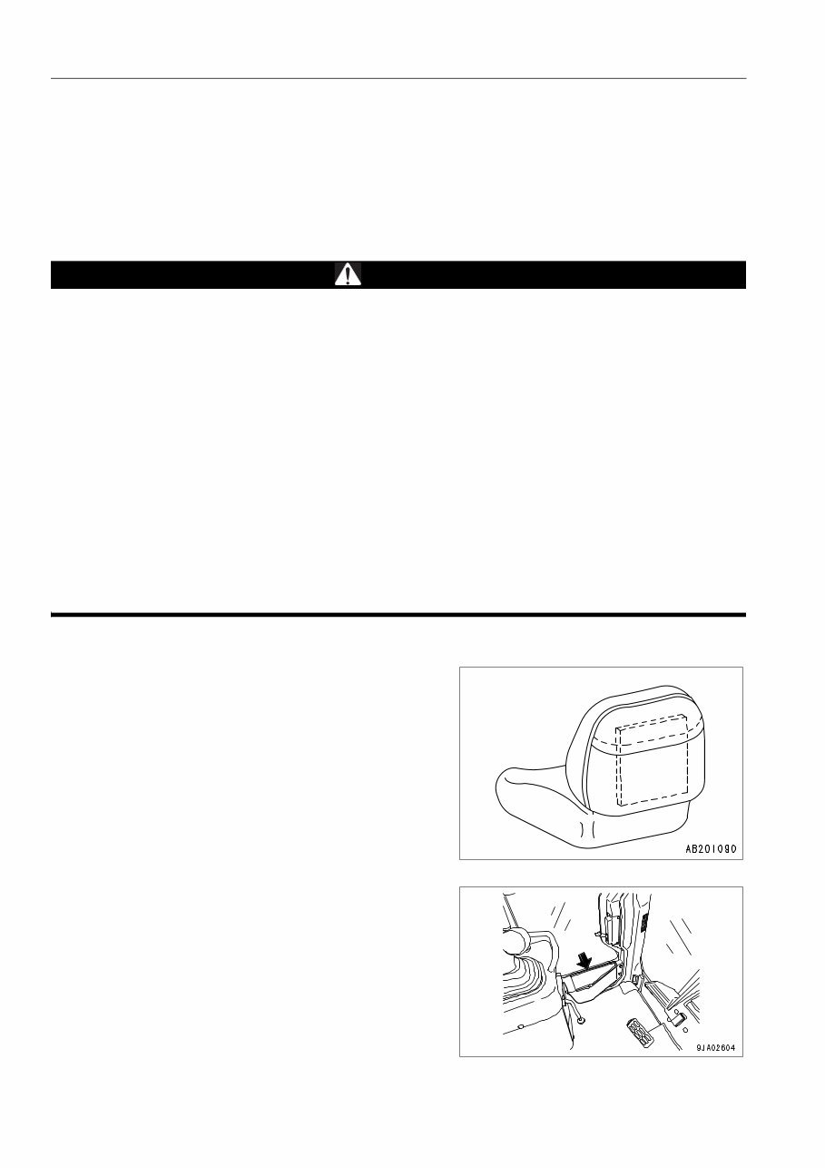
FOREWORD FOREWORD 1-2 FOREWORD 1 This manual provides rules and guidelines which will help you use this machine safely and effectively. The pre- cautions in this manual must be followed at all times when performing operation and maintenance. Most accidents are caused by the failure to follow fundamental safety rules for the operation and maintenance of machines. Acci- dents can be prevented by knowing beforehand conditions that may cause a hazard when performing operation and maintenance. WARNING Before beginning operation or maintenance, operators and maintenance personnel must always observe the following points. Read this manual thoroughly and understand its contents fully. Read the safety messages and safety labels given in this manual carefully so that they should be under- stood fully. Keep this manual at the storage location for the Operation and Maintenance Manual given below so that all personnel involved in working on the machine can consult it periodically. In case this manual should be lost or damaged, immediately contact Komatsu or your Komatsu distributor to obtain a new copy. When you sell the machine, make sure that this manual should be provided to the new owner together with the machine. In this manual, measurements are expressed in international standard units (SI). For the reference pur- pose, weight units used in the past are also displayed in { }. Storage location for the Operation and Maintenance Manual: If machine is equipped without cab. Pocket at rear of operator's seat If machine is equipped with a cab. Pocket at rear of operator's seat Inside of right and left doors
FOREWORD SAFETY INFORMATION 1-3 SAFETY INFORMATION 1 To enable you to use this machine safely, safety precautions and labels are given in this manual and affixed to the machine to give explanations of situations involving potential hazards and of the methods of avoiding such situa- tions. Signal words The following signal words are used to inform you that there is a potential hazardous situation that may lead to per- sonal injury or damage. In this manual and on machine labels, the following signal words are used to express the potential level of hazard. Example of safety message using signal word WARNING When standing up from the operator's seat, always place the safety lock lever in the LOCK position. If you accidentally touch the control levers when they are not locked, this may cause a serious injury or death. Other signal words In addition to the above, the following signal words are used to indicate precautions that should be followed to pro- tect the machine or to give information that is useful to know. Indicates an imminently hazardous situation which, if not avoided, will result in death or serious injury. Indicates a potentially hazardous situation which, if not avoided, could result in death or serious injury. Indicates a potentially hazardous situation which, if not avoided, may result in minor or moderate injury. This word is used also to alert against unsafe practices that may cause property damage. NOTICE This word is used for precautions that must be taken to avoid actions which could shorten the life of the machine. REMARK This gives information that is useful to know. DANGER WARNING CAUTION
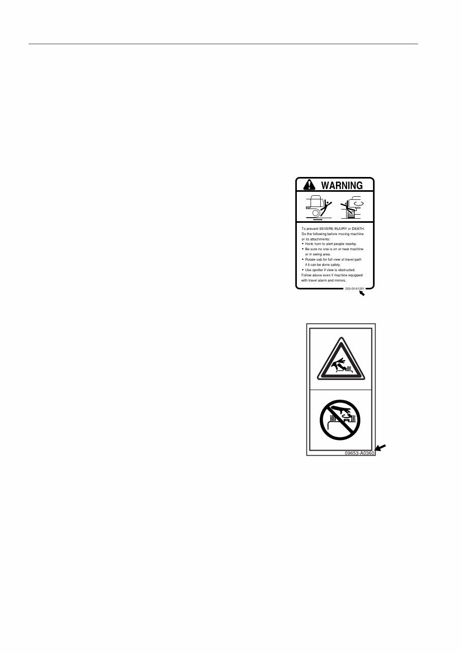
SAFETY INFORMATION FOREWORD 1-4 q Safety labels Safety labels are affixed to the machine to inform the operator or maintenance worker on the spot when carrying out operation or maintenance of the machine that may involve hazard. This machine uses “Safety labels using words“ and “Safety labels using pictograms“ to indicate safety procedures. Example of safety label using words Safety labels using pictogram Safety pictograms use a picture to express a level of hazard- ous condition equivalent to the signal word. These safety pic- tograms use pictures in order to let the operator or maintenance worker understand the level and type of hazard- ous condition at all times. Safety pictograms show the type of hazardous condition at the top or left side, and the method of avoiding the hazardous con- dition at the bottom or right side. In addition, the type of haz- ardous condition is displayed inside a triangle and the method of avoiding the hazardous condition is shown inside a circle. Komatsu cannot predict every circumstance that might involve a potential hazard in operation and maintenance. Therefore, the safety messages in this manual and on the machine may not include all possible safety precau- tions. If any procedures or actions not specifically recommended or allowed in this manual are used, it is your responsi- bility to take the necessary steps to ensure safety. In no event should you engage in prohibited uses or actions described in this manual. The explanations, values, and illustrations in this manual were prepared based on the latest information available at that time. Continuing improvements in the design of this machine can lead to changes in detail which may not be reflected in this manual. Consult Komatsu or your Komatsu distributor for the latest available information of your machine or for questions regarding information in this manual. The numbers in circles in the illustrations correspond to the numbers in ( ) in the text. (For example: 1 -> (1)) Part No. Part No
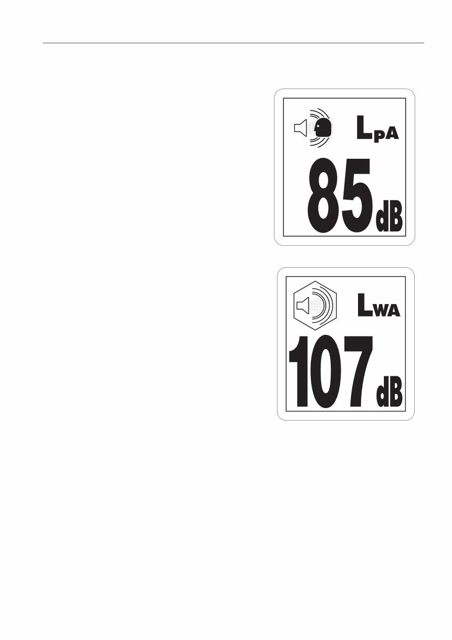
FOREWORD SAFETY INFORMATION 1-5 NOISE q Sound pressure level at the operator's station, measured according to ISO6396 (Dynamic test method, simulated working cycle) q Sound power level emitted. This is the guaranteed value as specified in European directive 2000/14/EC. VIBRATION When used for its intended purpose, levels of vibration for the earthworking machine transmitted from the operator’s seat are lower or equal to the test vibrations for the relative machinery class in compliance with ISO 7096. The actual acceleration value of the upper limbs in less than 2.5 m/s². The actual accel- eration value for the body is less than 0.8 m/s². These values were determined using a representative machine and with the help of the measurement procedures that are defined in the directives ISO 2631/1 and ISO 5349.
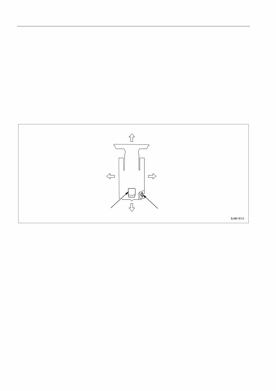
INTRODUCTION FOREWORD 1-6 INTRODUCTION 1 This Komatsu machine is designed to be used mainly for the following work: q Dozing q Smoothing q Cutting into hard or frozen ground or ditching See the section “WORK POSSIBLE USING BULLDOZER (3-95)“ for further details. FRONT/REAR, LEFT/RIGHT DIRECTIONS OF MACHINE 1 In this manual, the terms front, rear, left, and right refer to the travel direction as seen from the operator's seat when the operator's seat is facing the front and the sprocket is at the rear of the machine. Front Right Rear Left Operator’s seat Sprocket
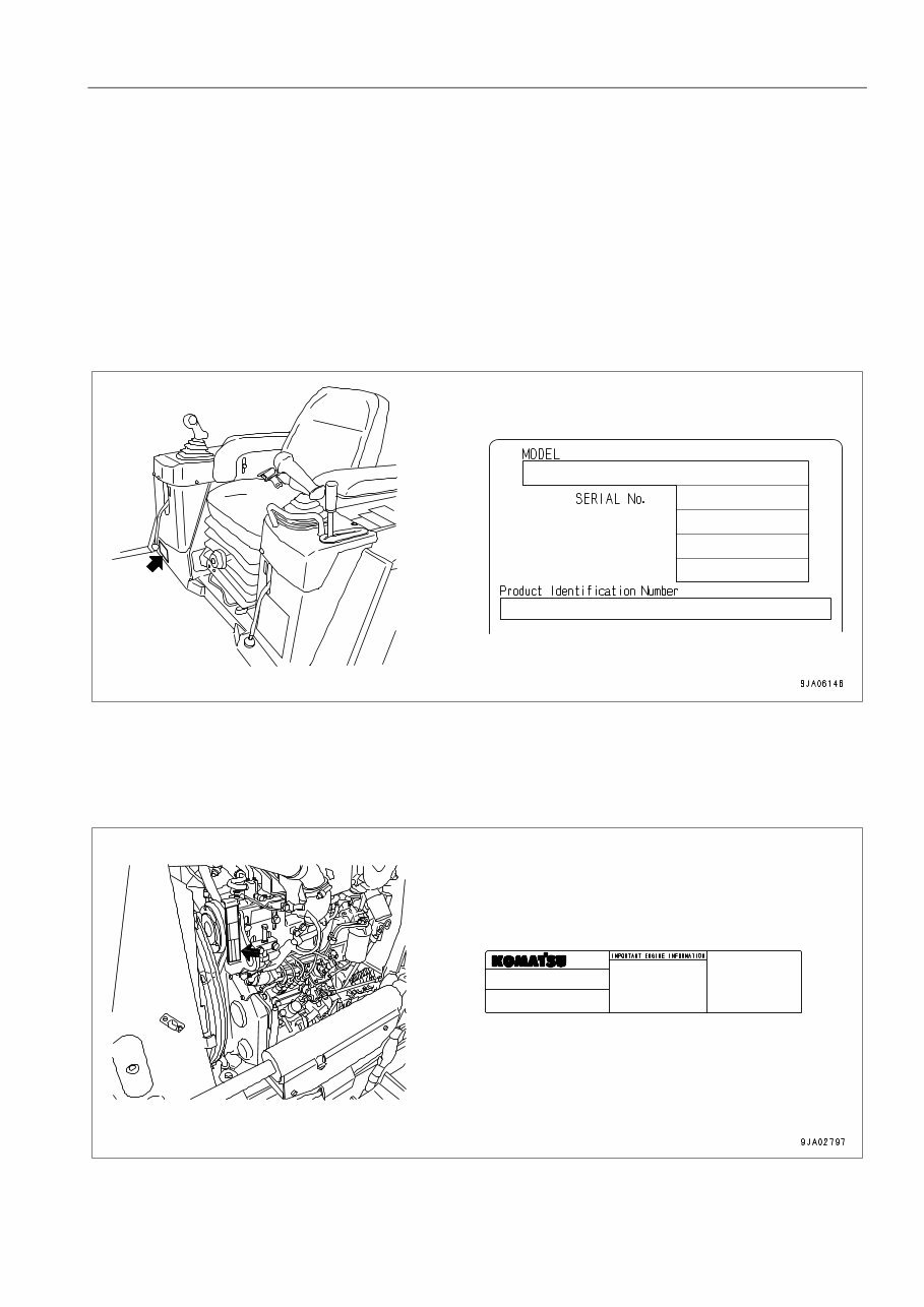
FOREWORD NECESSARY INFORMATION 1-7 NECESSARY INFORMATION 1 When requesting service or ordering replacement parts, please inform your Komatsu distributor of the following items. PRODUCT IDENTIFICATION NUMBER (PIN)/MACHINE SERIAL NO. PLATE 1 This is at the front bottom right of the operator's seat. The design of the nameplate differs according to the territory. ENGINE SERIAL NO. PLATE 1 This is at the front top of the engine on the left side machine. EPA: Environmental Protection Agency, U.S.A.
NECESSARY INFORMATION FOREWORD 1-8 POSITION OF SERVICE METER 1 The service meter is provided at the lower part of the monitor panel. TABLE OF ENTER SERIAL NO. AND DISTRIBUTORN 1 Machine serial No. Engine serial No. Product Identification Number Manufacturers name: Address: KOMATSU LTD. 3-6 Akasaka Minato-ku, 101 Tokyo Japan Distributor Address Phone Service personnel for your machine:
The Komatsu Bulldozer D31EX D37EX D39EX Operation Maintenance Manual provides essential information for the maintenance and operation of these bulldozers. It includes a comprehensive maintenance schedule, service procedures, and lubrication instructions. The manual covers topics such as the central lubrication system, changing lubrication intervals, oil change procedures, and tightening torques for bolts and nuts.
Additionally, it offers guidance on periodic parts replacement, limit values for slopes, maintenance and inspection procedures, and the replacement of the injector assembly. The joystick steering system and components are explained in detail, along with safety information and prohibited operations.
The manual is available in English and can be printed. It is compatible with both Windows and Mac operating systems.