D85A,E,P-21 MACHINE MODEL SERIAL NUMBER D85A-21 35001 and up D85E-21 35001 and up D85P-2 1 3001 and up . This shop manual may contain attachments and optional equipment that are not available in your area. Please consult your local Komatsu distributor for those items you may re- quire. Materials and specifications are subject to change without notice. . D85A, E, P-21 mounts the S6D125-1 and S6D125-2 engine. For details of the engine, see the 6D125 Series and 125-2 Series Engine Shop Manual. 0 1995 KOHAmJ All Rights Reserved 09-95(02)00901 00-l @iI
SAFETY SAFETY NOTICE SAFETY SAFETY NOTICE IMPORTANT SAFETY NOTICE Proper service and repair is extremely important for safe machine operation. The service and repair techniques recommended by Komatsu and described in this manual are both effective and safe. Some of these techniques require the use of tools specially designed by Komatsu for the specific purpose. To prevent injury to workers, the symbol A is used to mark safety precautions in this manual. The cautions accompanying these symbols should always be followed care- fully. If any dangerous situation arises or may possibly arise, first consider safety, and take the necessary actions to deal with the situation. GENERAL PRECAUTIONS Mistakes in operation are extremely dangerous. Read the Operation and Maintenance Manual carefully BEFORE operating the machine. 1. Before carrying out any greasing or repairs, read all the precautions given on the decals which are fixed to the machine. 2. When carrying out any operation, always wear safety shoes and helmet. Do not wear loose work clothes, or clothes with buttons missing. . Always wear safety glasses when hitting parts with a hammer. . Always wear safety glasses when grind- ing parts with a grinder, etc. 3. If welding repairs are needed, always have a trained, experienced welder carry out the work. When carrying out welding work, al- ways wear welding gloves, apron, glasses, cap and other clothes suited for welding work. 4. When carrying out any operation with two or more workers, always agree on the oper- ating procedure before starting. Always in- form your fellow workers before starting any step of the operation. Before starting work, hang UNDER REPAIR signs on the controls in the operator’s compartment. 5. Keep all tools in good condition and learn the correct way to use them. 6. Decide a place in the repair workshop to keep tools and removed parts. Always keep the tools and parts in their correct places. Always keep the work area clean and make sure that there is no dirt or oil on the floor. Smoke only in the areas provided for smok- ing. Never smoke while working. PREPARATIONS FOR WORK 7. a. Before adding oil or making any repairs, park the machine on hard, level ground, and block the wheels or tracks to prevent the machine from moving. Before starting work, lower blade, ripper, bucket or any other work equipment to the ground. If this is not possible, insert the safety pin or use blocks to prevent the work equipment from falling. In addition, be sure to lock all the control levers and hang warn- ing signs on them. 9. When bisassembling or assembling, support the machine with blocks, jacks or stands before starting work. 10. Remove all mud and oil from the steps or other places used to get on and off the ma- chine. Always use the handrails, ladders or steps when getting on or off the machine. Never jump on or off the machine. If it is impossible to use the handrails, ladders or steps, use a stand to provide safe footing. 00-3
SAFETY SAFETY NOTICE PRECAUTIONS DURING WORK 11. When removing the oil filler cap, drain plug or hydraulic pressure measuring plugs, loosen them slowly to prevent the oil from spurting out. Before disconnecting or removing compo- nents of the oil, water or air circuits, first remove the pressure completely from the circuit. 12. 13. The water and oil in the circuits are hot when the engine is stopped, so be careful not to get burned. Wait for the oil and water to cool before carrying out any work on the oil or water circuits. Before starting work, remove the leads from the battery. Always remove the lead from the negative (-1 terminal first. 14. When raising heavy components, use a hoist or crane. Check that the wire rope, chains and hooks are free from damage. Always use lifting equipment which has ample capacity. Install the lifting equipment at the correct places. Use a hoist or crane and operate slowly to prevent the component from hit- ting any other part. Do not work with any part still raised by the hoist or crane. 15. When removing covers which are under in- ternal pressure or under pressure from a spring, always leave two bolts in position on opposite sides. Slowly release the pres- sure, then slowly loosen the baits to remove. 16. When removing components, be careful not to break or damage the wiring. Damaged wiring may cause electrical fires. 17. When removing piping, stop the fuel or oil from spilling out. If any fuel or oil drips onto the floor, wipe it up immediately. Fuel or oil on the floor can cause you to slip, or can even start fires. 18. As a general rule, do not use gasoline to wash parts. In particular, use only the mini- mum of gasoline when washing electrical parts. 21 22. 23. 24. 19. Be sure to assemble all parts again in their original places. Replace any damaged parts with new parts. . When installing hoses and wires, be sure that they will not be damaged by contact with other parts when the machine is be- ing operated. 20. When installing high pressure hoses, make sure that they are not twisted. Damaged tubes are dangerous, so be extremely care- ful when installing tubes for high pressure circuits. Also, check that connecting parts are correctly installed. When assembling or installing parts, always use the specified tightening torques. When installing protective parts such as guards, or parts which vibrate violently or rotate at high speed, be particularly careful to check that they are installed correctly. When aligning two holes, never insert your fingers or hand. Be careful not to get your fingers caught in a hole. When measuring hydraulic pressure, check that the measuring tool is correctly assem- bled before taking any measurements. Take care when removing or installing the tracks of track-type machines. When removing the track, the track sepa- rates suddenly, so never let anyone stand at either end of the track. 00-4
FOREWORD GENERAL FOREWORD GENERAL This shop manual has been prepared as an aid to improve the quality of repairs by giving the serviceman an accurate understanding of the product and by showing him the correct way to perform repairs and make judgements. Make sure you understand the contents of this manual and use it to full effect at every opportunity. This shop manual mainly contains the necessary technical information for operations performed in a service workshop. For ease of understanding, the manual is divided into the following chapters; these chapters are further divided into the each main group of components. STRUCTURE AND FUNCTION This section explains the structure and function of each component. It serves not only to give an understanding of the structure, but also serves as reference material for troubleshooting. TESTING AND ADJUSTING This section explains checks to be made before and after performing repairs, as well as adjustments to be made at completion of the checks and repairs. Troubleshooting charts correlating “Problems” to “Causes’ are also included in this section. s DISASSEMBLY AND ASSEMBLY ;: z This section explains the order to be followed when removing, installing, disassembling or assembling each component, as well as precautions to be taken for these operations. MAINTENANCE STANDARD This section gives the judgement standards when inspecting disassembled parts. NOTICE The specifications contained in this shop manual are subject to change at any time and without any advance notice. Use the specifications given in the book with the latest date. 00-5
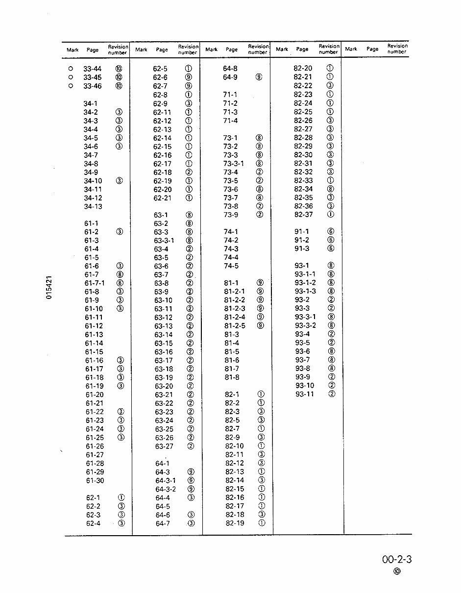
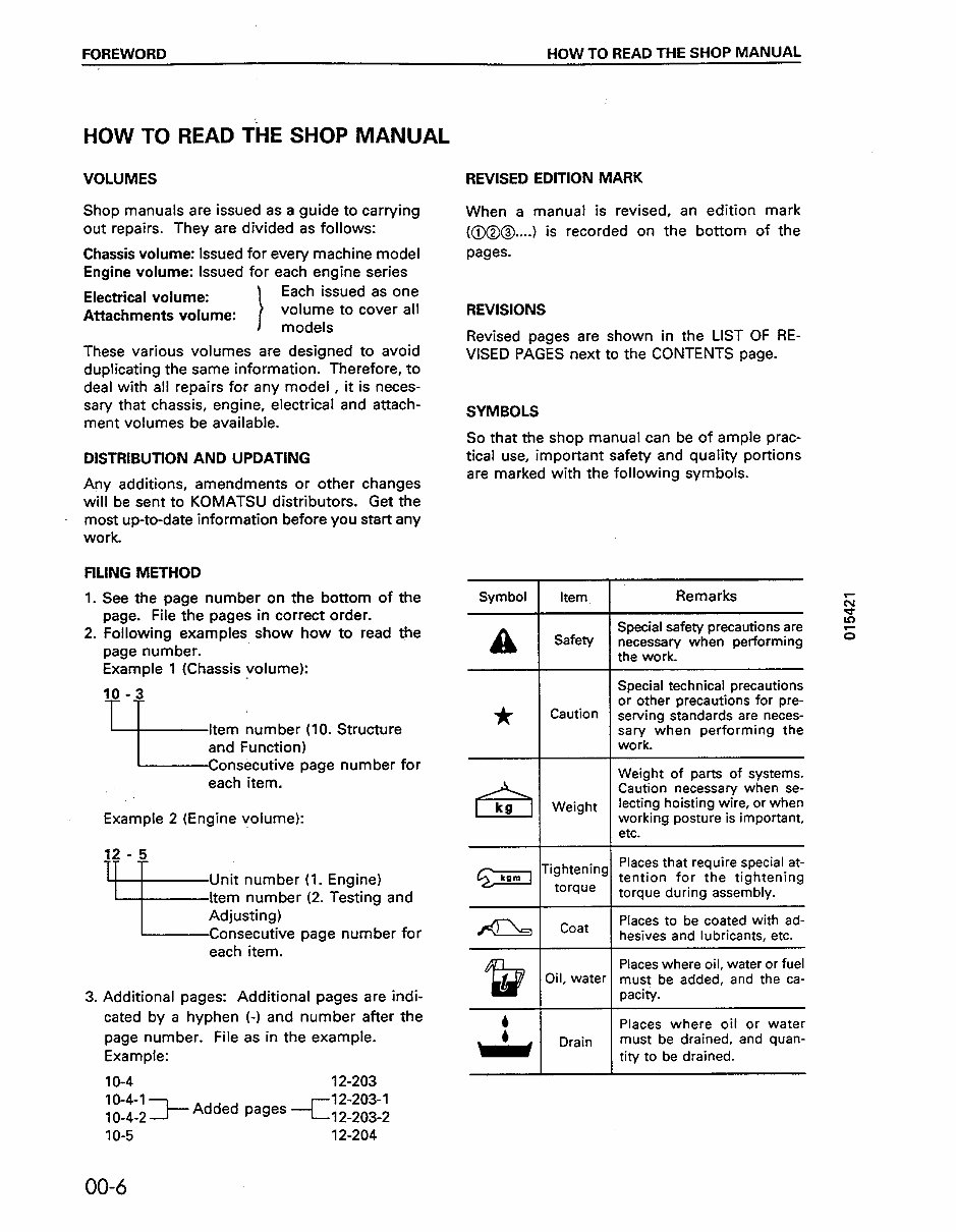
FOREWORD HOW TO READ THE SHOP MANUAL HOW TO READ THE SHOP MANUAL VOLUMES Shop manuals are issued as a guide to carrying out repairs. They are divided as follows: Chassis volume: Issued for every machine model Engine volume: Issued for each engine series Electrical volume: 1 Each issued as one Attachments volume: I volume to cover all models These various volumes are designed to avoid duplicating the same information. Therefore, to deal with all repairs for any model , it is neces- sary that chassis, engine, electrical and attach- ment volumes be available. DISTRIBUTION AND UPDATING Any additions, amendments or other changes will be sent to KOMATSU distributors. Get the most up-to-date information before you start any work. FlLlNG METHOD 1. See the page number on the bottom of the page. File the pages in correct order. 2. Following examples show how to read the page number. Example 1 (Chassis volume): 10 -3 TT Item number (IO. Structure ~$sPe%?~~age number for each item. Example 2 (Engine volume): 18 -!j Unit number (1. Engine) Item number (2. Testing and Adjusting) Consecutive page number for each item. 3. Additional pages: Additional pages are indi- cated by a hyphen (-1 and number after the page number. File as in the example. Example: IO-4 12-203 12-203-I Added pages -Cl 2-203-2 REVISED EDlTlON MARK When a manual is revised, an edition mark (@@@..__) is recorded on the bottom of the pages. REVISIONS Revised pages are shown in the LIST OF RE- VISED PAGES next to the CONTENTS page. SYMBOLS So that the shop manual can be of ample prac- tical use, important safety and quality portions are marked with the following symbols. Symbol A * h g Specral safety precautrons are Special technical precautions or other precautions for pre- Caution serving standards are neces- sary when performing the work. Places that require special at- tention for the tightening torque during assembly. Places to be coated with ad- hesives and lubricants, etc. Places where oil, water or fuel water must be added, and the ca- 1 pacity. 4 Places where oil or water must be drained and quan- A Drain tity to be drained. 1o-5 12-204 00-6
Our repair manuals are essential resources for both professional mechanics and DIY enthusiasts. They provide comprehensive information on the following topics:
General Information
Routine Maintenance
Engine Removal and Installation
Fuel System
Lubrication and Cooling System
Engine Specifications
Transmission, Drive Chain & Sprockets
Steering System
Shocks
Body Work
Intake & Exhaust
Electrical System
Advanced Troubleshooting
And more!
Our repair manuals are available in electronic format, either as .OVA files or .PDF files. They are easily accessible and can be printed for use without the risk of damage from grease and dirt. With our electronic repair manuals, you can quickly locate the relevant information and make on-the-spot repairs using a smart device, minimizing downtime on the job site.
For added convenience, all our repair manuals come with a Lifetime Protection Policy. In the event of loss or damage, simply contact us for a free replacement.
We offer a wide range of repair service manuals, workshop manuals, owner's manuals, parts catalogs, and other electronic resources for various machines, including UTVs, motorcycles, ATVs, quads, snowmobiles, Seadoos, equipment, small engines, inboards, outboards, and more.
Instant access is available after payment, with no shipping costs. You can start the repair process immediately without any waiting time. If you are unable to find a specific manual, please contact our customer support team, and we will make every effort to locate and list it for you.
Thank you for choosing our repair manuals for your maintenance and repair needs.