Komatsu D37E-5 Bulldozer Workshop Repair Service Manual
What's Included?
Lifetime Access
Fast Download Speeds
Online & Offline Access
Access PDF Contents & Bookmarks
Full Search Facility
Print one or all pages of your manual
SEBMOOI 007 Shop Manual D31 E,P,Pl,l’ll=~o D31 BOA D31 &ho D37E=!i,D37p=sr BULLDOZERS This material is proprietary to Komatsu America International Company and is not to be reproduced, used, or disciosed except in accordance with written authorization from Komatsu America lntemational Company. It is our policy to improve our products whenever it is possible and practical to do so. We reserve the right to make changes or add improvements at any time wlthout Incurring any obligation to install such changes on products sold previously. Due to this continuous program of research and development, periodic revisions may be made to this publication. It is recommended that customers contact their distributor for information on the latest revision. May 1997 Copyright 1997 Komatsu America International Company oo&
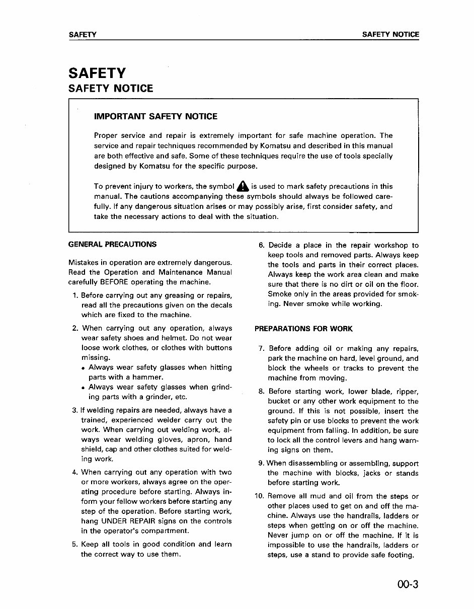
SAFETY SAFETY NOTICE SAFETY SAFETY NOTICE IMPORTANT SAFETY NOTICE Proper service and repair is extremely important for safe machine operation. The service and repair techniques recommended by Komatsu and described in this manual are both effective and safe. Some of these techniques require the use of tools specially designed by Komatsu for the specific purpose. To prevent injury to workers, the symbol A is used to mark safety precautions in this manual. The cautions accompanying these symbols should always be followed care- fully. If any dangerous situation arises or may possibly arise, first consider safety, and take the necessary actions to deal with the situation. Mistakes in operation are extremely dangerous. Read the Operation and Maintenance Manual carefully BEFORE operating the machine. 1. 2. Before carrying out any greasing or repairs, read all the precautions given on the decals which are fixed to the machine. When carrying out any operation, always wear safety shoes and helmet. Do not wear loose work clothes, or clothes with buttons missing. . Always wear safety glasses when hitting parts with a hammer. 6. Decide a place in the repair workshop to keep tools and removed parts. Always keep the tools and parts in their correct places. Always keep the work area clean and make sure that there is no dirt or oil on the floor. Smoke only in the areas provided for smok- ing. Never smoke while working. PREPARATIONS FOR WORK GENERAL PRECAUTIONS 7. . Always wear safety glasses when grind- ing parts with a grinder, etc. %. 3. If welding repairs are needed, always have a trained, experienced welder carry out the work. When carrying out welding work, al- ways wear welding gloves, apron, hand shield, cap and other clothes suited for weld- Before adding oil or making any repairs, park the machine on hard, level ground, and block the wheels or tracks to prevent the machine from moving. Before starting work, lower blade, ripper, bucket or any other work equipment to the ground. If this is not possible, insert the safety pin or use blocks to prevent the work equipment from falling. In addition, be sure to lock all the control levers and hang warn- ing signs on them. ing work. 4. When carrying out any operation with two or more workers, always agree on the oper- ating procedure before starting. Always in- form your fellow workers before starting any step of the operation. Before starting work, hang UNDER REPAIR signs on the controls in the operator’s compartment. 5. Keep all tools in good condition and learn the correct way to use them. 9. When disassembling or assembling, support the machine with blocks, jacks or stands IO. before starting work. Remove all mud and oil from the steps or other places used to get on and off the ma- chine. Always use the handrails, ladders or steps when getting on or off the machine. Never jump on or off the machine. If it is impossible to use the handrails, ladders or steps, use a stand to provide safe footing. 00-3
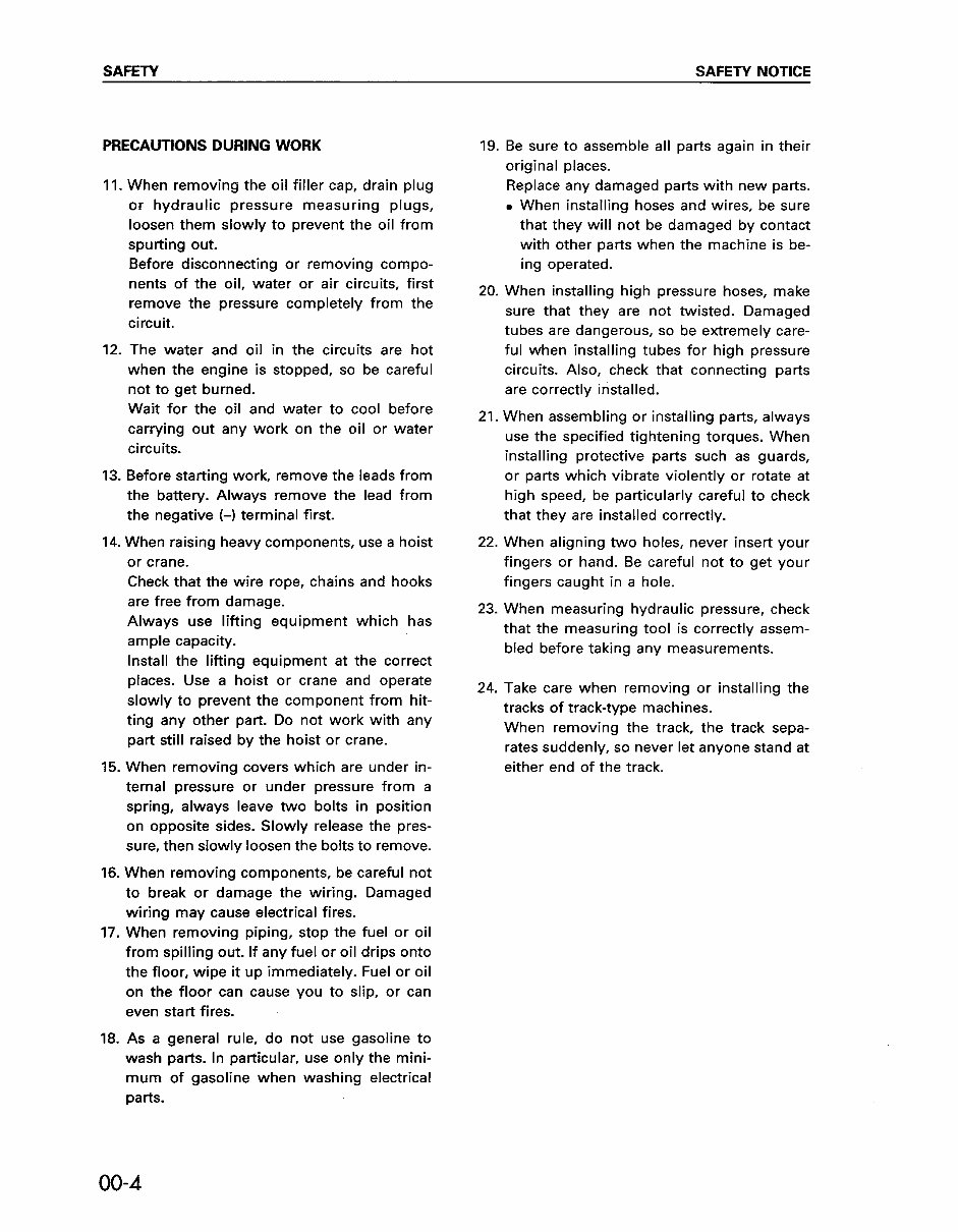
SAFETY SAFETY NOTICE PRECAUTIONS DURING WORK 11 When removing the oil filler cap, drain plug or hydraulic pressure measuring plugs, loosen them slowly to prevent the oil from spurting out. Before disconnecting or removing compo- nents of the oil, water or air circuits, first remove the pressure completely from the circuit. 12. The water and oil in the circuits are hot when the engine is stopped, so be careful not to get burned. Wait for the oil and water to cool before carrying out any work on the oil or water circuits. 13. Before starting work, remove the leads from the battery. Always remove the lead from the negative (-1 terminal first. 14. 15. 16. 17. 18. When raising heavy components, use a hoist or crane. Check that the wire rope, chains and hooks are free from damage. Always use lifting equipment which has ample capacity. Install the lifting equipment at the correct places. Use a hoist or crane and operate slowly to prevent the component from hit- ting any other part. Do not work with any part still raised by the hoist or crane. When removing covers which are under in- ternal pressure or under pressure from a spring, always leave two bolts in position on opposite sides. Slowly release the pres- sure, then slowly loosen the bolts to remove. When removing components, be careful not to break or damage the wiring. Damaged wiring may cause electrical fires. When removing piping, stop the fuel or oil from spilling out. If any fuel or oil drips onto the floor, wipe it up immediately. Fuel or oil on the floor can cause you to slip, or can even start fires. As a general rule, do not use gasoline to wash parts. In particular, use only the mini- mum of gasoline when washing electrical parts. 19. 20. 21 Be sure to assemble all parts again in their original places. Replace any damaged parts with new parts. . When installing hoses and wires, be sure that they will not be damaged by contact with other parts when the machine is be- ing operated. When installing high pressure hoses, make sure that they are not twisted. Damaged tubes are dangerous, so be extremely care- ful when installing tubes for high pressure circuits. Also, check that connecting parts are correctly installed. 22. When aligning two holes, never insert your When assembling or installing parts, always use the specified tightening torques. When installing protective parts such as guards, or parts which vibrate violently or rotate at high speed, be particularly careful to check that they are installed correctly. fingers or hand. Be careful not to get your fingers caught in a hole. 23. When measuring hydraulic pressure, check that the measuring tool is correctly assem- bled before taking any measurements. 24. Take care when removing or installing the tracks of track-type machines. When removing the track, the track sepa- rates suddenly, so never let anyone stand at either end of the track. 00-4
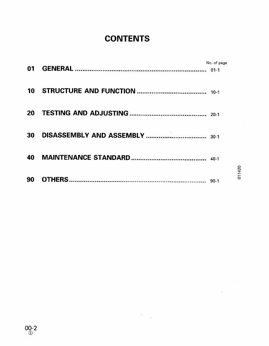
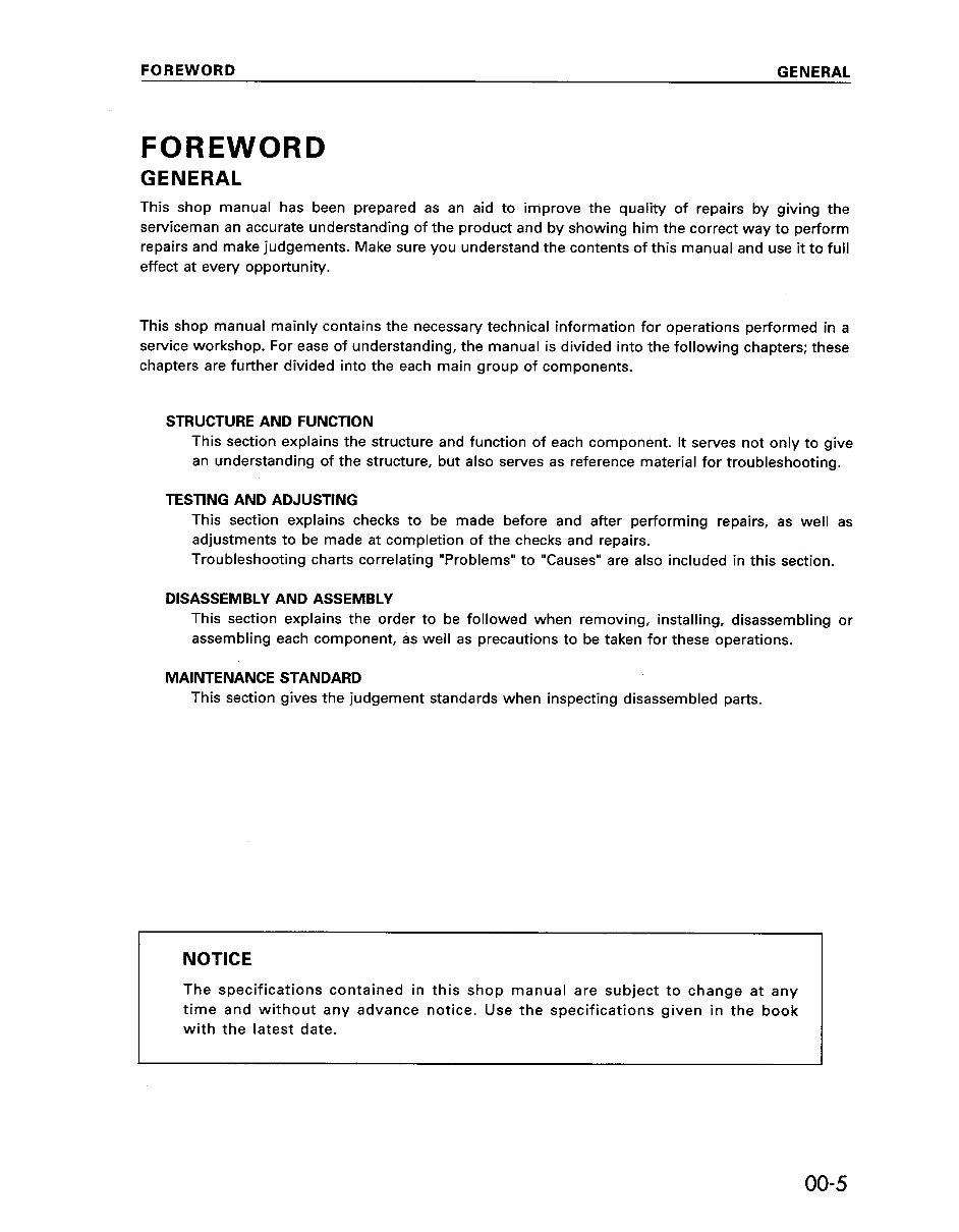
FOREWORD GENERAL FOREWORD GENERAL This shop manual has been prepared as an aid to improve the quality of repairs by giving the serviceman an accurate understanding of the product and by showing him the correct way to perform repairs and make judgements. Make sure you understand the contents of this manual and use it to full effect at every opportunity. This shop manual mainly contains the necessary technical information for operations performed in a service workshop. For ease of understanding, the manual is divided into the following chapters; these chapters are further divided into the each main group of components. STRUCTURE AND FUNCTION This section explains the structure and function of each component. It serves not only to give an understanding of the structure, but also serves as reference material for troubleshooting. TESTING AND ADJUSTING This section explains checks to be made before and after performing repairs, as well as adjustments to be made at completion of the checks and repairs. Troubleshooting charts correlating “Problems” to “Causes” are also included in this section. DISASSEMBLY AND ASSEMBLY This section explains the order to be followed when removing, installing, disassembling or assembling each component, as well as precautions to be taken for these operations. MAINTENANCE STANDARD This section gives the judgement standards when inspecting disassembled parts. NOTICE The specifications contained in this shop manual are subject to change at any time and without any advance notice. Use the specifications given in the book with the latest date. 00-5
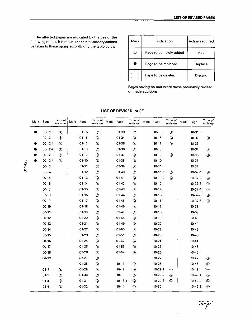
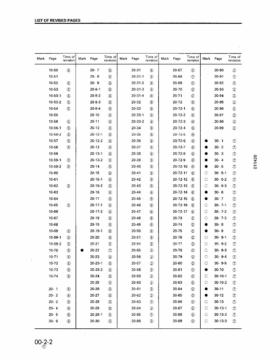
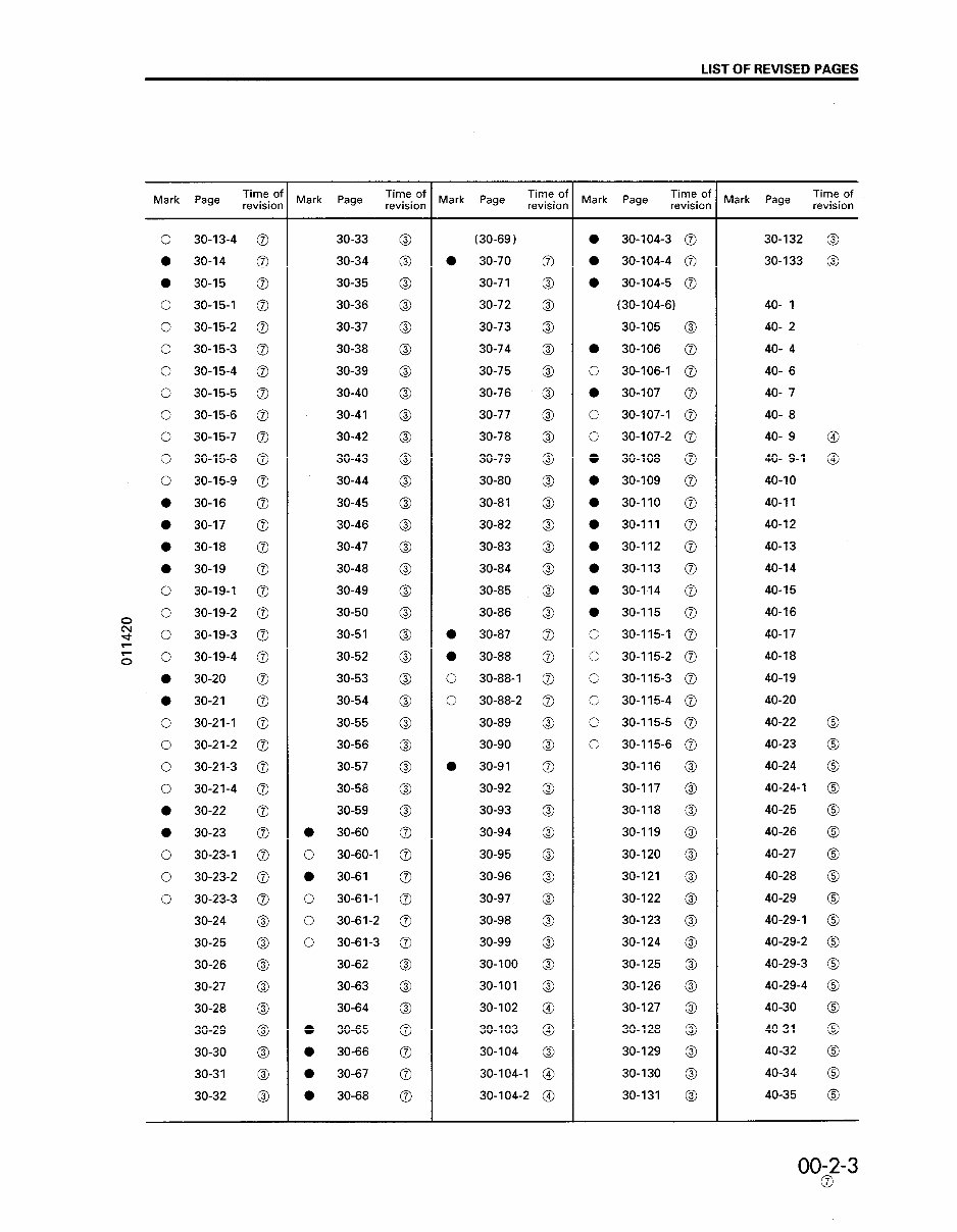
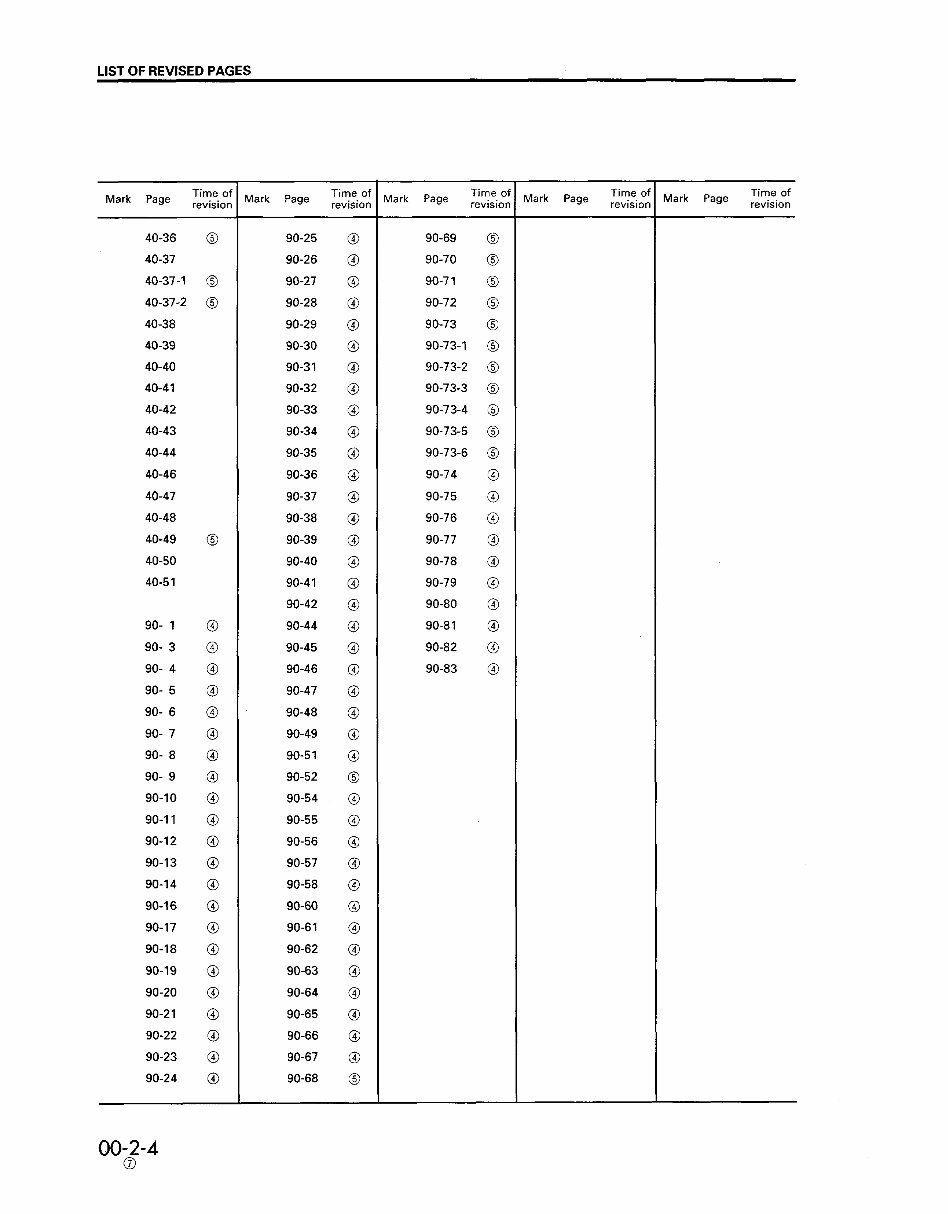
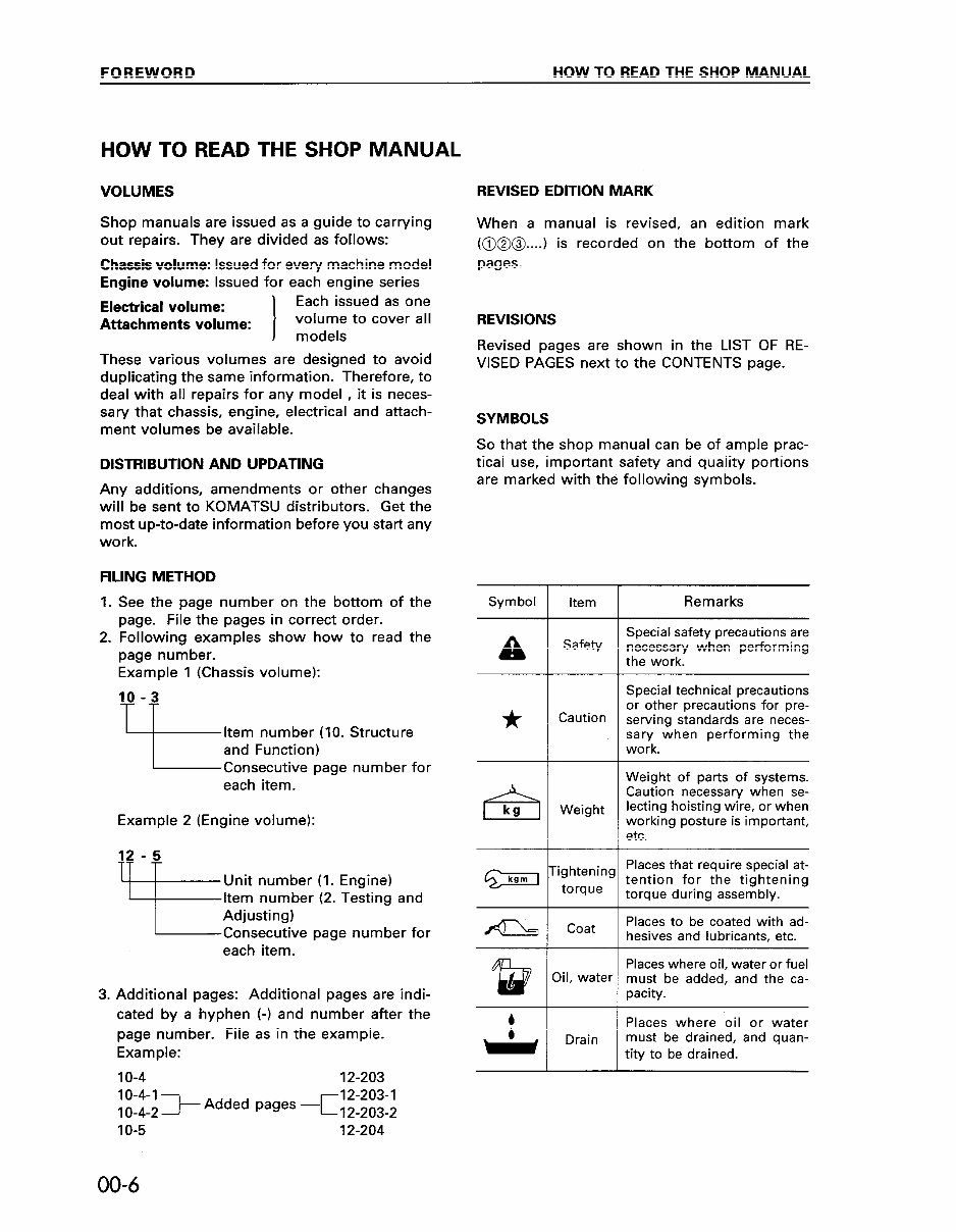
FOREWORD HOW TO READ THE SHOP MANUAL HOW TO READ THE SHOP MANUAL VOLUMES Shop manuals are issued as a guide to carrying out repairs. They are divided as follows: Chassis volume: Issued for every machine model Engine volume: Issued for each engine series Electrical volume: Each issued as one Attachments volume: I volume to cover all models These various volumes are designed to avoid duplicating the same information. Therefore, to deal with all repairs for any model , it is neces- sary that chassis, engine, electrical and attach- ment volumes be available. DISTRIBUTION AND UPDATING Any additions, amendments or other changes will be sent to KOMATSU distributors. Get the most up-to-date information before you start any work. FILING METHOD 1. See the page number on the bottom of the page. File the pages in correct order. 2. Following examples show how to read the page number. Example 1 (Chassis volume): 10 -3 Item number (IO. Structure and Function) Consecutive page number for each item. Example 2 (Engine volume): Unit number (1. Engine) Item number (2. Testing and Adjusting) Consecutive page number for each item. 3. Additional pages: Additional pages are indi- cated by a hyphen (-1 and number after the page number. File as in the example. Example: IO-4 12-203 REVISED EDITION MARK When a manual is revised, an edition mark (@@@...J is recorded on the bottom of the pages. REVISIONS Revised pages are shown in the LIST OF RE- VISED PAGES next to the CONTENTS page. SYMBOLS So that the shop manual can be of ample prac- tical use, important safety and quality portions are marked with the following symbols. Symbol a * el kg Item Safety Caution Weight ighteninc torque Coat Xl, water Drain I Remarks Special safety precautions are necessary when performing the work. Special technical precautions or other precautions for pre- serving standards are neces- sary when performing the work. Weight of parts of systems. Caution necessary when se- lecting hoisting wire, or when working posture is important, etc. Places that require special at- tention for the tightening torque during assembly. Places to be coated with ad- hesives and lubricants, etc. Places where oil, water or fuel must be added, and the ca- pacity. Places where oil or water must be drained, and quan- tity to be drained. 10-4-I - 1O-4-2 > Added pages -c~f~~~~~~ IO-5 12-204 00-6
This workshop service manual for the Komatsu D37E-5 Bulldozer is designed for mechanical technicians familiar with service procedures for BRP products. It covers repair and overhaul of the bulldozer, assuming familiarity with general automobile practices. The manual includes instructions on components manufactured for the bulldozer, as well as repairs of proprietary components. It provides reliable information and emphasizes particular information denoted by the wording and symbols: WARNING, CAUTION, NOTE.
The manual offers diagnostic and repair procedures, making it useful for both professional mechanics and DIY enthusiasts. It also emphasizes the importance of safety equipment and precautions when working on the bulldozer, including the use of a torque wrench and special tools for adjustments or repairs.
Owners will find that owning and referring to this manual will make it possible to be better informed and to more knowledgeably perform repairs like a professional automotive technician. The manual contains specifications and procedures available in an authorized Komatsu D37E-5 Bulldozer dealer service department.
It includes information and procedures for routine maintenance and servicing, such as tune-ups, maintenance, removal & install procedures, assemblies & disassemblies, fuel system, ignition, lubrication system, exhaust, electrical system, and more extensive repairs involving engine and transmission disassembly.
This is a .PDF manual and is delivered electronically via email. The content depicts parts and/or procedures applicable to the particular product at the time of writing.
General Information
Maintenance
Lubrication
Heating
Ventilation
Air Conditioning
Suspension
Front Suspension
Rear Suspension
Wheel
Tire System
Differential
Driveline
Drive Shaft
Transfer Case
Brakes
Engine
Engine Mechanical
Engine Cooling
Engine Fuel
Engine Electrical
Ignition System
Starting
Charging System
Emissions
Engine Exhaust
Engine Lubrication
Engine Speed Control System
Clutch
Cooling
Electronic Control Modules
Engine Systems
Heated Systems
Horn
Ignition Control
Instrument Cluster
Lamps
Power Systems
Restraints
Speed Control
Transmission
Exhaust System
Body Structure
Seats
Security and Locks
Air Bag System
Exterior Trim
Interior Trim
Frame
Bumpers
Fuel System
Steering
Transmission and Transfer Case
Tires
Wheels
Heating
Air Conditioning
Emissions Control
Engine Removal
Engine Installation
Final Drive
Electrical System
Air cleaner element renewal
Air cleaner temperature control check
Auxiliary drivebelt check
Battery electrolyte level check
Battery terminal check
Brake hydraulic fluid renewal
Brake hydraulic system seal and hose renewal
Brake pipe and hose check
Choke adjustment check
Contact breaker point renewal and distributor lubrication
Crankcase ventilation system check
Emission control filter element renewal
Engine coolant renewal
Engine idle speed check
Engine oil and filter renewal
Engine valve clearance check - OHV engines
Exhaust system check
Fluid leak check
Fluid level checks
Front and rear brake pad/shoe check
Front wheel alignment check
Gearbox oil level check
Handbrake check
Hinge and lock check and lubrication
HT lead, distributor cap
Ignition circuit check
Ignition timing
Contact breaker gap (dwell angle) check
Intensive maintenance
Mixture adjustment check
Road test
Roadwheel security check
Seat belt check
Spark plug check
Spark plug renewal
Steering and suspension security check
Throttle damper operation check
Timing belt renewal
Tyre checks
Underbody inspection
Wiper blade check
Recently Viewed
5,521,897Happy Clients
2,594,462eManuals
1,120,453Trusted Sellers
15Years in Business
Price:
Actual Price:
Komatsu D37E-5 Bulldozer Workshop Repair Service Manual