TM 9-2815-213-34 TECHNICAL MANUAL DIRECT SUPPORT AND GENERAL SUPPORT MAINTENANCE MANUAL (INCLUDING DIRECT SUPPORT, AND GENERAL SUPPORT REPAIR PARTS LIST AND DEPOT MAINTENANCE ALLOWANCES) FOR ENGINE, DIESEL, WITH ACCESSORIES CUMMINS MODEL V8-300 (2815-910-8217) This copy is a reprint which includes current pages from Changes 1 and 2. HEADQUARTERS, DEPARTMENT OF THE ARMY FEBRUARY 1972
TM 9-2815-213-34 C2 CHANGE HEADQUARTERS DEPARTMENT OF THE ARMY No. 2 WASHINGTON, DC, 26 November 1976 Direct Support and General Support Maintenance Manual (Including Direct Support, and General Support Repair Parts and Special Tools List For ENGINE, DIESEL, WITH ACCESSORIES CUMMINS MODEL V8-300 (2815-00-910-8217) Current as of 6 April 1976 TM 9-2815-213-34, 2 February 1972, is changed as follows: 1. Remove old pages and insert new pages as indicated below. New or changed material is indicated by a vertical bar in the margin of the page. Added or revised illustrations are indicated by a vertical bar next to the identification number. Remove pages Insert pages 3-9and3-10 3-9 and 3-10 3-31 and 3-32 3-31 and 3-32 3-35 and 3-36 3-35 and 3-36 3-61 and 3-62 3-61 and 3-62 3-67 and 3-68 3-67 and 3-68 B-7 through B-18 B-7 through B-18 B-21 through B-24 B-21 through B-24 B-43 and B-44 B-43 and B-44 B-61 and B-62 B-61 and B-62 B-67 through B-87 B-77 through B-87 2. File this change sheet in front of the publication for reference purposes. }
TM 9-2815-213-34 By Order of the Secretary of the Army: BERNARD W. ROGERS General, United States Army Official: Chief of Staff PAUL T. SMITH Major General, United States Army The Adjutant General Distribution: To be distributed in accordance with DA Form 12-38, Direct/General Support TM requirements for 10-ton truck tractor, M123, M123AlC, M123C, M123E2 and Cargo Truck, M125.
TM 9-2815-213-34 C1 CHANGE HEADQUARTERS DEPARTMENT OF THE ARMY No. 1 WASHINGTON, DC, 23 July 1975 Direct Support and General Support Maintenance Manual (Including Direct Support, and General Support Repair Parts and Special Tools List) For ENGINE, DIESEL, WITH ACCESSORIES CUMMINS MODEL V8-300 (2815-00-910-8217) Current as of 7 April 1975 TM 9-2815-213-34, 2 February 1972, is changed as follows: 1. Remove old pages and insert new pages as indicated below. New or changed material in the maintenance portion is indicated by a vertical bar in the margin of the page. Added or revised illustrations are indicated by a vertical bar next to the identification number. Remove pages Insert pages 3-57 and 3-58 3-57 and 3-58 3-61 and 3-62 3-61 and 3-62 B-1 thru B-38 B-1 thru B-27 B-59 and B-60 B-59 and B-60 None B-62.1 B-77 thru B-89 B-77 thru B-87 2. File this change sheet in front of the publication for reference purposes. By Order of the Secretary of the Army: FRED C. WEYAND General, United States Army, Official: Chief of Staff. VERNE L. BOWERS Major General, United States Army, The Adjutant General. Distribution: To be distributed in accordance with DA Form 12-38, (qty rqr block No. 92). Direct and General Support maintenance requirements for Truck, Tractor, 10-Ton, 6x6 M123A/C and M123E2. }
TM 9-2815-213-34 TECHNICAL MANUAL HEADQUARTERS DEPARTMENT OF THE ARMY No. 9-2815-21334 Washington D.C., 2 February 1972 DIRECT SUPPORT AND GENERAL SUPPORT MAINTENANCE MANUAL (INCLUDING DIRECT SUPPORT AND GENERAL SUPPORT REPAIR PARTS LIST AND DEPOT MAINTENANCE ALLOWANCES) FOR ENGINE, DIESEL, WITH ACCESSORIES CUMMINS MODEL V8-300 (2815-910-8217) Paragraph Page CHAPTER 1. INTRODUCTION Section I. General.................................................................................... 1-1 1-1 II. Description and Data ............................................................... 1-4 1-1 CHAPTER 2. MAINTENANCE INSTRUCTIONS Section I. Repair Parts, Special Tools and Equipment ........................... 2-1 2-1 II. General Maintenance .............................................................. 2-4 2-1 III. Removal of Engine Components ............................................ 2-8 2-3 CHAPTER 3. REPAIR INSTRUCTIONS Section I. General.................................................................................... 3-1 3-1 II. Repair of Cylinder Block .......................................................... 3-2 3-1 III. Repair of Crankshaft ............................................................... 3-7 3-3 IV. Repair of Connecting Rod and Piston Assembly .................... 3-13 3-5 V. Repair of Front Cover .............................................................. 3-19 3-8 VI. Repair of Oil Pump Assembly ................................................. 3-24 3-9 VII. Repair of Camshaft ................................................................. 3-30 3-11 VIII. Repair of Crankshaft Adapter .................................................. 3-36 3-12 IX. Repair of Flywheel Housing and Spacer Plate........................ 3-40 3-12 X. Repair of Oil Pan ..................................................................... 3-46 1-3 XI. Repair of Flywheel................................................................... 3-52 3-13 XII. Repair of Valve and Injector Tappets ...................................... 3-58 3-14 XIII. Repair of Cylinder Head .......................................................... 3-64 3-16 XIV. Repair of Fuel Injectors ........................................................... 3-71 3-23 XV. Repair of Rocker Arm Assembly and Push Rods ................... 3-80 3-33 XVI. Repair of Push Rod Cavity Covers.......................................... 3-86 3-35 XVII. Repair of Cylinder Head Covers.............................................. 3-91 3-35 XVIII. Repair of Air Compressor and Drive Assembly....................... 3-96 3-36 XIX. Repair of Fuel Pump and Fuel Lines....................................... 3-102 3-6 XX. Repair of Water Crossover Pipe and Lifting Eyes ................... 3-110 3-52 XXI. Repair of Air Intake, Preheater Assembly and Intake Manifolds 3-114 3-52 XXII. Repair of Water Pump Assembly ............................................ 3-120 3-53 XXIII. Repair of Fan Drive Pulley, Vibration Damper and Water Pump 3-125 3-2 Pulley Assembly XXIV. Repair of Thermostat Assembly .............................................. 3-131 3-54 XXV. Repair of Fan, Fan Hub, and Bracket Assembly ..................... 3-137 3-56 XXVI. Repair of Hydraulic Pump and Mounting Brackets ................. 3-143 3-56 XXVII. Repair of Alternator Assembly and Mounting Bracket ............ 3-149 3-56 XXVIII. Repair of Starter Assembly ..................................................... 3-155 3-56 *This manual supersedes TM 9-2015-213-34, 13 April 1966 including all changes. i }
*TM 9-2815-213-34 Paragraph Page CHAPTER 3. REPAIR INSTRUCTIONS--Continued XXIX. Repair of Oil Cooler .............................................................................. 3-157 3-56 XXX. Repair of Exhaust Manifolds ................................................................ 3-162 3-57 XXXI. Engine Removal from Engine Rebuild Stand ....................................... 3-162 3-57 XXXII. Engine Test and Adjustment ................................................................ 3-167 3-57 XXXIII. Repair and Rebuild Standards ............................................................. 3-174 3-62 APPENDIX A. REFERENCES B. REPAIR PARTS AND SPECIAL TOOLS LIST Section I. Introduction........................................................................................... ..................... B-1 II. Repair Parts List ................................................................................... ..................... B-4 Group 01 -ENGINE 0100 Engine Assembly.................................................................................. ..................... B-4 0101 Block and Cylinder Head ...................................................................... ..................... B-5 0102 Crankshaft ............................................................................................ ..................... B-7 0103 Flywheel Assembly............................................................................... ..................... B-7 0104 Piston and Connecting Rod.................................................................. ..................... B-8 0105 Valves and Camshaft ........................................................................... ..................... B-8 0106 Engine Lubrication System................................................................... ..................... B-10 0108 Manifolds .............................................................................................. ..................... B-13 Group 03 -FUEL SYSTEM 0301 Fuel Injector.......................................................................................... ..................... B-14 0302 Fuel Pump ............................................................................................ ..................... B-15 0304 Air Cleaner ........................................................................................... ..................... B-20 0311 Starting Aids ......................................................................................... ..................... B-20 Group 05 -COOLING SYSTEM 0503 Thermostat ........................................................................................... ..................... B-21 0504 Water Pump ......................................................................................... ..................... B-22 0505 Fan Assembly....................................................................................... ..................... B-22 Group 06 -ELECTRICAL SYSTEM 0601 Generator ............................................................................................. ..................... B-22 Group 12 -BRAKES 1209 Air Compressor and Drive Mechanism ................................................ ..................... B-23 Group 14 -STEERING 1410 Hydraulic Pump Assembly ................................................................... ..................... B-23 Group 33 -SPECIAL PURPOSE KITS 3301 Reusable Shipping Containers............................................................. ..................... B-24 Group 47 -GAGES 4701 Tachometer .......................................................................................... ..................... B-24 Section III. Special Tools List Group 26 -TOOLS AND TEST EQUIPMENT 2604 Special Tools ........................................................................................ ..................... B-25 2606 Test Equipment .................................................................................... ..................... B-27 Section IV. Index-Federal Stock Number and Reference Number Cross-Reference to Figure and Item Number ................................................................................. ..................... Index-1 ii
*TM 9-2815-213-34 LIST OF ILLUSTRATIONS Number Title Page Number Title Page 1-1. Model V8-300 ...... Engine Assembly 3/4 Left 3-12. Piston Ring Gap Check ..................................... 3-7 Front View ................................................. 1-2 3-13. Rod Side Clearance Check ............................... 3-8 1-2. Model V8-300 Engine Assembly 3/4 Right ... 3-14. Crankshaft Oil Seal-Removal/Installation .......... 3-9 Rear View ................................................ 1-3 3-15. Front Cover Bore Alinement Check .................. 3-9 1-3. Engine Assembly Rear Sectional View ......... 1-6 3-16. Front Cover to Block Alinemen t Check ............. 3-9 2-1. Exhaust Manifold-Removal/Installation ......... 2-4 3-17. Drive Gear Backlash Check ............................. 3-10 2-2. Oil Cooler-Removal Installation ..................... 2-5 3-18. Camshaft End Play Check ............................... 3-11 2-3. Engine Rebuild Stand-Removal/ ................... 3-19. Crankshaft Gear Backlash Check ..................... 3-11 Installation .................................................. 2-5 3-20. Crankshaft Adapter Tightening Sequence ........ 3-12 2-4. Fan Hub and Bracket Assembly- ................... 3-21. Flywheel Housing Concentricity Check ........... 3-13 Removal/Installation ................................. 2-5 3-22. Flywheel Tightening Sequence ......................... 3-14 2-5. Thermostat Assembly-Removal/ ................... 3-23. Flywheel Bearing Bore and Wobble Limits 3-14 Installation ................................................. 2-6 3-24. Tappet Assembly Test ...................................... 3-15 2-6. Drive Pulleys and Vibration Damper- ............ 3-25. Cylinder Head in Holding Fixture ..................... 3-16 Removal/Installation .................................. 2-6 3-26. Valve Assemblies-Removal/Installation ............ 3-16 2-7. Water Pump Assembly-Removal .................. 3-27. Injector Sleeves-Removal/Installation .............. 3-16 Installation ................................................. 2-6 3-28. Crosshead Guide-Removal/Installation ............. 3-16 2-8. Air Intake Crossover and Preheater .............. 3-29. Valve Seat Removal Sectional View ................. 3-17 Assembly-Removal/Installation .................. 2-7 3-30. Injector Sleeve Holder Installation .................... 3-17 2-9. Intake Manifold, Fuel Pump and Fuel ............ 3-31. Injector Tip Protrusion Measurement ................ 3-17 Lines-Removal/Installation ........................ 2-7 3-32. Valve Head and Collet Check ........................... 3-18 2-10. Water Crossover Pipe and Lifting Eye .......... 3-33. Crosshead Guide Check ................................. 3-18 Removal/Installation ................................. 2-8 3-34. Valve Guide Check ........................................... 3-18 2-11. Oil Dipstick Tube Assembly-Removal/ .......... 3-35. Valve Spring Test ............................................ 3-18 Installation ................................................. 2-8 3-46. Valve and Injector Counterbore Measure- . 2-12. Cylinder Head Covers-Removal/ ................... ments ................................................................ 3-19 Installation .................................................. 2-9 3-37. Cylinder Head Regrooving ................................ 3-19 2-13. Crankcase Breather Tube Removal/ ............. 3-38. Valve Guide Installation .................................... 3-20 Installation .................................................. 2-9 3-39. Crosshead Guide Installation- ........................... 3-20 2-14. Push Rod Cavity Covers-Removal/ ............... 3-40. Injector Sleeve Installation ............................... 3-20 Installation .................................................. 2-9 3-41. Injector Sleeve Rolling-Upper Portion ............... 3-21 2-15. Rocker Arms and Push Rods-Removal/ ........ 3-42. Injector Sleeve Rolling-Lower Portion ............... 3-21 Installation .................................................. 2-10 3-43. Injector Sleeve Seat Cutting .............................. 3-21 2-16. Injector Clamps Removal/Installation ............ 2-10 3-44. Valve Seat Insert Counterbore ......................... 3-21 2-17. Fuel Injector and Hold-Down Clamp .............. 2-10 3-45. Intake Valve Port Swirl Plate Installation ........... 3-22 2-18. Valve Crossheads-Removal/Installation ........ 2-11 3-46. Valve Seat Insert Peering ................................. 3-22 2-19. Cylinder Head-Removal/,Installation ............. 2-11 3-47. Valve Seat Test.3 .............................................. 3-22 2-20. Valve and Injector Tappets-Removal/ ........... 3-48. Cylinder Head Tightening Sequence ................ 3-23 Installation .................................................. 2-11 3-49. Fuel Injector PT (Type C) .................................. 3-24 2-21. Flywheel-Removal/Installation ....................... 2-12 3-50. Injector Cup-Removal/Installation ..................... 3-24 2-22. Crankshaft Adapter-Removal/Installation 2-12 3-51. Injector Link-Removal/Installation ..................... 3-24 2-23. Flywheel Housing-Removal/Installation ......... 2-13 3-52. Plunger Seat Pattern ........................................ 3-24 2-24. Camshaft Gear, and Spacer Plate- ............... 3-53. Fuel Injector-Exploded View.............................. 3-26 Removal/Installation .................................. 2-13 3-54. Injector Check Ball Seating ............................... 3-26 2-25. Oil Pan-Removal/Installation ......................... 2-13 3-55. Injector Body 0-Ring Installation ....................... 3-26 2-26. Oil Pump Assembly-Removal/Installation 2-13 3-56. Injector Body and Plunger Markings ................. 3-27 2-27. Front Cover-Removal/Installation .................. 2-14 3-57. Injector Cup Markings ...................................... 3-27 2-28. Connecting Rod and Piston Assembly- ......... 3-58. Injector Plunger Seat Test ................................. 3-27 Removal/Installation .................................. 2-14 3-59. Injector Test Stand- ........................................... 3-29 2-29. Crankshaft and Main Bearings-Removal/ ...... 3-60. Alining Timing Wheel and Pointer ..................... 3-29 Installation .................................................. 2-14 3-61. Hydraulic and Air Valves ................................... 3-29 3-1. Camshaft Bushing Removal ......................... 3-1 3-62. Air Pressure Adjustment ................................... 3-30 3-2. Cylinder Sleeve Removal ............................. 3-1 3-63. Master Injector Installation- ............................... 3-30 3-3. Main Bearing Bore Alinement Check ............. 3-2 3-64. Fuel Inlet Installation ......................................... 3-30 3-4. Cylinder Sleeve Seals Installation ................. 3-2 3-65. Injector Mounted in Test Stand ......................... 3-30 3-5. Crankshaft Dimensions ................................. 3-4 3-66. Test Stand Air Pressure Connection ................. 3-31 3-6. Crankshaft End Clearance Check ................. 3-5 3-67. Load Cell Test ................................................... 3-31 3-7. Bearing Cap to Block Clearance Check ........ 3-5 3-68. Ball Seat Resurfacing ........................................ 3-32 3-8. Side Bolt Tightening Sequence ..................... 3-5 3-69. Orifice Hole Burnishing Tool Installation ........... 3-33 3-9. Piston and Ring Assembly ............................ 3-6 3-70. Orifice Plug Burnishing ..................................... 3-33 3-10. Connecting Rod Check ................................. 3-6 3-72. Injector Push Rod Timing ................................. 3-33 3-11. Ring Groove Wear Check ............................. 3-7 3-72. Air Compressor Drive Gear Timing Mark .......... 3-37 iii
*TM 9-2815-213-34 LIST OF ILLUSTRATIONS-Continued Number Title Page Number Title Page 3-73. Fuel Pump PT (Type G) ......................... 3-38 3-108. Gear Train-Points of Measurement .......... 3-67 3-74. Mounting Plate and Ball Joint Vise .......... 3-109. Oil Pressure Regulator and Oil Pump- Installation ............................................ 3-39 Point of Measurement ............................... 3-39 3-75. Governor Weights Assembly-Removal/ .. 3-110. Cylinder Head-Points of Measurement ..... 3-69 Installation ............................................ 3-39 3-111. Tappets and Push Rod/Points of 3-76. Governor Shaft Oil Seals-Removal/ ........ Measurement ............................................. 3-69 Installation ........................................... 3-39 3-112. Rocker Arms and Shaft-Points of 3-77. Tachometer Drive Assembly-Removal/... Measurement ............................................ 3-70 Installation ............................................ 3-39 3-113. Water Pump-Points of Measurement ........ 3-71 3-78. Plunger Assembly-Removal/Assembly ... 3-40 3-114. Assembly Data-Points of Measurement..... 3-72 3-79. Fuel Pump Test Stand Equipment .......... 3-42 B-1. Engine and Container Assembly................ B-39 3-80. Fuel Pump Test Stand ............................ 3-43 B-2. Cylinder Block and Head Assembly .......... B-40 3-81. Mounting Pump on Test Stand ............... 3-44 B-3. Crankshaft Main Bearing and Drive Pulley B-41 3-82. Engaging Stand Drive Shaft ................... 3-45 B-4. Flywheel Assembly ..................................... B-42 3-83. Pump Preparation for Test and Calibration 3-46 B-5. Connecting Rod, Piston and Rings ........... B-43 3-84. Fuel Pump Nameplate............................. 3-46 B-6. Cylinder Head, Valves, Rocker Arms and 3-85. Scribing Governor Barrel ......................... 3-47 Covers ........................................................ B-44 3-86. Reaming Mainshaft Bushing ................... 3-47 B-7. Front Cover and Camshaft ......................... B-45 3-87. Throttle Shaft 0-ring Installation ............. 3-47 B-8. Engine Lubrication System (crankcase 3-88. Throttle Assembly Installation ................ 3-47 breather)..................................................... B-46 3-89. Thrust Washer-Drive Plunger Governor.. B-9. Engine Lubrication System (oil pan) .......... B-47 Clearance ............................................ 3-48 B-10. Engine Lubrication System (pump) ........... B-48 3-90. Main Throttle Shaft Shim Check ............ 3-49 B-11. Engine Lubrication System (oil cooler) ...... B-49 3-91. Weep Hole Leakage ................................ 3-49 B-12. Manifold intake and Exhaust ...................... B-50 3-92. Governor Spring Shimming .................... 3-50 B-13. Fuel Injector ............................................... B-51 3-93. Throttle Stop Screw Adjust ...................... 3-50 B-14. Fuel Pump Assembly ................................. B-52 3-94. Idle Speed Setting .................................. 3-51 B-15. Fuel Pump Housing (exploded) ................. B-53 3-95. Valve Timing Marks ................................. 3-58 B-16. Fuel Pump Gear and Damper Assembly ... B-54 3-96. Engine Firing Order ................................. 3-59 B-17. Fuel Shut-off and Solenoid Valve and 3-97. Crosshead Adjustments .......................... 3-59 Governor Spring Pack Assembly .............. B-55 3-98. Engine Blow-By Check ........................... 3-63 B-18. Governor Assembly (main shaft cover) ..... B-56 3-99. Manifold Fuel Pressure Check ............... 3-63 B-19. Air Intake Components ............................. B-57 3-100. Fuel Flow Rate Check ............................ 3-63 B-20. Glow Plug and Heater Accessories ........... B-58 3-101. Performance Curve ................................. 3-64 B-21. Thermostat and Crossover Tube ............... B-59 3-102. Cylinder Block-Points of Measurement ... 3-65 B-22. Water Pump .............................................. B-60 3-103. Crankshaft and Bearings Points of .......... B-23. Fan, Hub, and Bracket ............................... B-61 Measurement ...................................... 3-65 B-24. Generator ................................................... B-62 3-104. Connecting Rod-Points of Measurement 3-66 B-25. Air Compressor and Drive Mechanism ...... B-63 3-105. Piston-Points of Measurement ............... 3-66 B-26. Power Steering Pump ................................ B-64 3-106. Cylinder Sleeve-Points of Measurement . 3-67 B-27. Tachometer Drive ...................................... B-65 3-107. Camshaft and Bearings-Points of ........... B-28. Special Tools...................................... B-66 B-74 Measurement ...................................... 3-67 B-29. Test Equipment.................................. B-75 B-76 LIST OF CHARTS Number Title Page Number Title Page 3-1. Injection Timing ......................................... 3-33 3-2. Fuel Pump Troubleshooting................... 3-51 iv
*TM 9-2815-213-34 CHAPTER 1 INTRODUCTION Section I. General 1-1. Scope a. This technical manual contains instruction for direct and general support maintenance of the Cummins Diesel Engine, Model V8-300, (fig. 1-1 and 1-2). It contains descriptions of, and procedures for, disassembly, inspection, repair, rebuild, and assembly of the engine. b. Appendix A contains a list of current refer ences, including supply manuals, forms, technical manuals, and other available publications applicable to the engine. c. Appendix B lists repair parts, special tools, and test equipment required for the performance of direct and general support maintenance of the engine. 1-2. Forms and Records Maintenance forms, records, and reports which are to be used by maintenance personnel at all maintenance levels are listed in and prescribed by TM 38-750. 1-3. Reporting of Equipment Publication Improvement The reporting of errors, omissions, and recommendations for improving this publication by the individual user is encouraged. Reports should be submitted on DA Form 2028, Recommended Changes to Publications, and forwarded direct to the Commanding General, U.S. Army Tank-Automotive Command Attention: ASMTA-4, Warren, MI 48090. Section II. Description and Data 1-4. Description a. General. (1) In this manual the following terms will be used to identify the location for engine parts and assemblies: (a) Front-fan end of engine. (b) Rear-flywheel end of engine. (c) Right and Left-are identified as viewed from the rear. (2) The model V8-300 diesel engine is as eight cylinder, V-type, Valve-in-head, water cooled, compression-ignition engine, using the four stroke cycle principle of operation. The four strokes consist of intake, compression, power and exhaust. Intake and exhaust valves, and fuel injectors, are operated from a single camshaft. The intake stroke of the cycle brings filtered, heated air to the cylinders. The compression stroke compresses the air (17:1 compression ratio) to 500-600 p.s.i, and raises the cylinder temperature to approximately 1000 degrees Fahrenheit. During the top of the compression stroke and start of the power stroke, a metered charge of diesel fuel is injected into the cylinders. The high temperature within the cylinders ignites the diesel fuel resulting in the power stroke. The fourth stroke of the cycle exhausts the burned gases from the cylinders. Proper engine operation depends upon the high compression of the intake air and the timed injection of the correct measure of diesel fuel into the cylinder. b. Engine Assembly. The model V8-300 engine (fig. 1-1 and 1-2) is a diesel eight cylinder V-type, valve in head, water cooled, compression ignition engine. The engine is rated 300 horsepower at 3000 rpm and will operate on diesel fuel. c. Engine Systems. (1) Fuel System. The system consists of a filter, fuel pump with governor, fuel passages, and injectors (one for each cylinder). The system is designed so that the volume of liquid flow is proportionate to the fluid pressure, the time allowed to flow, and the size of the orifice fuel flows through. The pump draws fuel from the vehicle supply tank and delivers it to each injector. A governor controls the flow of fuel from the gear pump, as well as the idle and maximum engine speed. (2) Lubrication System. All working parts of the engine are pressure lubricated. Oil is supplied by a dual- type gear driven lubricating pump located below the crankshaft and driven by the crankshaft gear. On completion of the lubrication cycle, oil is accumulated in the oil pan sump by gravity and is drawn from this sump by the oil 1-1
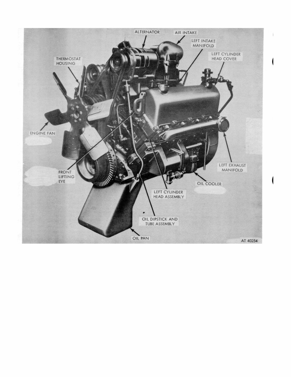
*TM 9-2815-213-34 Figure 1-1. Model V8-300 engine assembly--3/4 left front view. pump. Oil is delivered to all working parts of the engine through drillings in the block, cylinder head, crankshaft, and rocker levers. Lubricating oil is forced through the crankshaft to lubricate the main and connecting rod bearings. Lubricating oil pressure is controlled by a regulator which is an integral part of the oil pump assembly. The air compressor receives pressure lubrication from the engine oil supply. The oil flow cycle is as follows. (a) Oil is drawn to oil pump through suction tube, in oil pan. It is then pumped through a passage in rear of block through right bank water header cover to front of the block. (b) The oil flow crosses in front of block to left bank through oil filter and into cooler. From cooler, oil flows to left bank oil drilling at rear of engine. The oil pump by- pass dumps oil directly into pan. (c) From left bank oil drilling, at rear of engine, oil flows to no. 4 cam bushing and no. 4 main bearing which in turn supplies no. 3 and 7 connecting rods. (d) Right bank rocker arms are oiled intermittently through no. 5 cam bushing. (e) From left bank oil drilling, oil flows to left bank tappets, to no. 2 and 3 cam bushings, and no. 2 and 3 main bearings. No. 3 main bear- 1-2
This technical manual provides service, maintenance, troubleshooting, and replacement procedures for your dozer. It includes step-by-step instructions, clear images, and exploded-view illustrations.
The procedures, combined with illustrations, enable anyone to safely and efficiently service and repair their dozer. It contains comprehensive diagrams, detailed illustrations, and all the manufacturer's specifications and technical information.
Whether you are a professional mechanic or a DIY enthusiast, this manual equips you with the necessary information. It is accessible on various electronic devices, including PC & Mac computers, Android and Apple smartphones & tablets, etc. The manual is available in .pdf format and is printable. Adobe Reader (free) is required for viewing.