


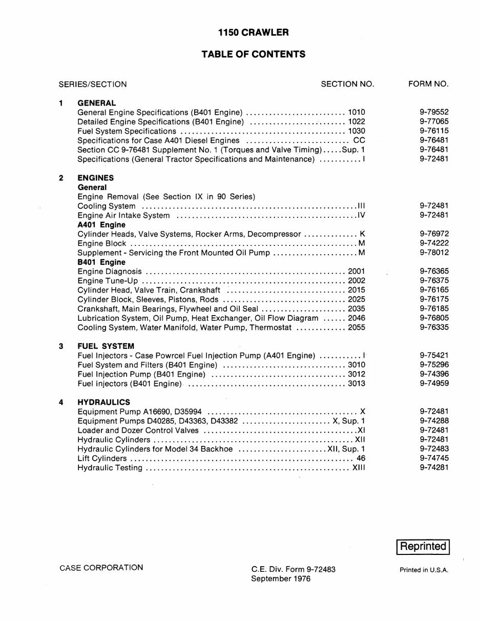
1150 CRAWLER
TABLE OF CONTENTS
SERIES/SECTION SECTION NO.
1 GENERAL
General Engine Specifications (B401 Engine) .......................... 1010
Detailed Engine Specifications (B401 Engine) ......................... 1022
Fuel System Specifications ........................................... 1030
Specifications for Case A401 Diesel Engines ........................... CC
Section CC 9-76481 Supplement No.1 (Torques and Valve Timing) ..... Sup. 1
Specifications (General Tractor Specifications and Maintenance) ........... I
2 ENGINES
General
Engine Removal (See Section IX in 90 Series)
Cooling System ........................................................ 111
Engine Air Intake System ............................................... IV
A401 Engine
Cylinder Heads, Valve Systems, Rocker Arms, Decompressor .............. K
Engine Block ........................................................... M
Supplement - Servicing the Front Mounted Oil Pump ...................... M
8401 Engine
Engine Diagnosis .................................................... 2001
Engine Tune-Up ..................................................... 2002
Cylinder Head, Valve Train, Crankshaft ~ .............................. 2015
Cylinder Block, Sleeves, Pistons, Rods ................................ 2025
Crankshaft, Main Bearings, Flywheel and Oil Seal ...................... 2035
Lubrication System, Oil Pump, Heat Exchanger, Oil Flow Diagram ...... 2046
Cooling System, Water Manifold, Water Pump, Thermostat ............. 2055
3 FUEL SYSTEM
Fuel Injectors - Case Powrcel Fuel Injection Pump (A401 Engine) ........... I
Fuel System and Filters (B401 Engine) ................................ 3010
Fuel Injection Pump (B401 Engine) ................................... 3012
Fuel Injectors (B401 Engine) ......................................... 3013
4 HYDRAULICS
Equipment Pump A16690, D35994 ....................................... X
Equipment Pumps D40285, D43363, D43382 ....................... X, Sup. 1
Loader and Dozer Control Valves ........................................ XI
Hydraulic Cylinders .................................................... XII
Hydraulic Cylinders for Model 34 Backhoe ....................... XII, Sup. 1
Lift Cylinders .......................................................... 46
Hydraulic Testing ..................................................... XIII
CASE CORPORATION
C.E. Div. Form 9-72483
Septem ber 1976
FORM NO.
9-79552
9-77065
9-76115
9-76481
9-76481
9-72481
9-72481
9-72481
9-76972
9-74222
9-78012
9-76365
9-76375
9-76165
9-76175
9-76185
9-76805
9-76335
9-75421
9-75296
9-74396
9-74959
9-72481
9-74288
9-72481
9-72481
9-72483
9-74745
9-74281
I Reprinted I
Printed in U.S.A.
SERI ES/SECTION SECTION NO.
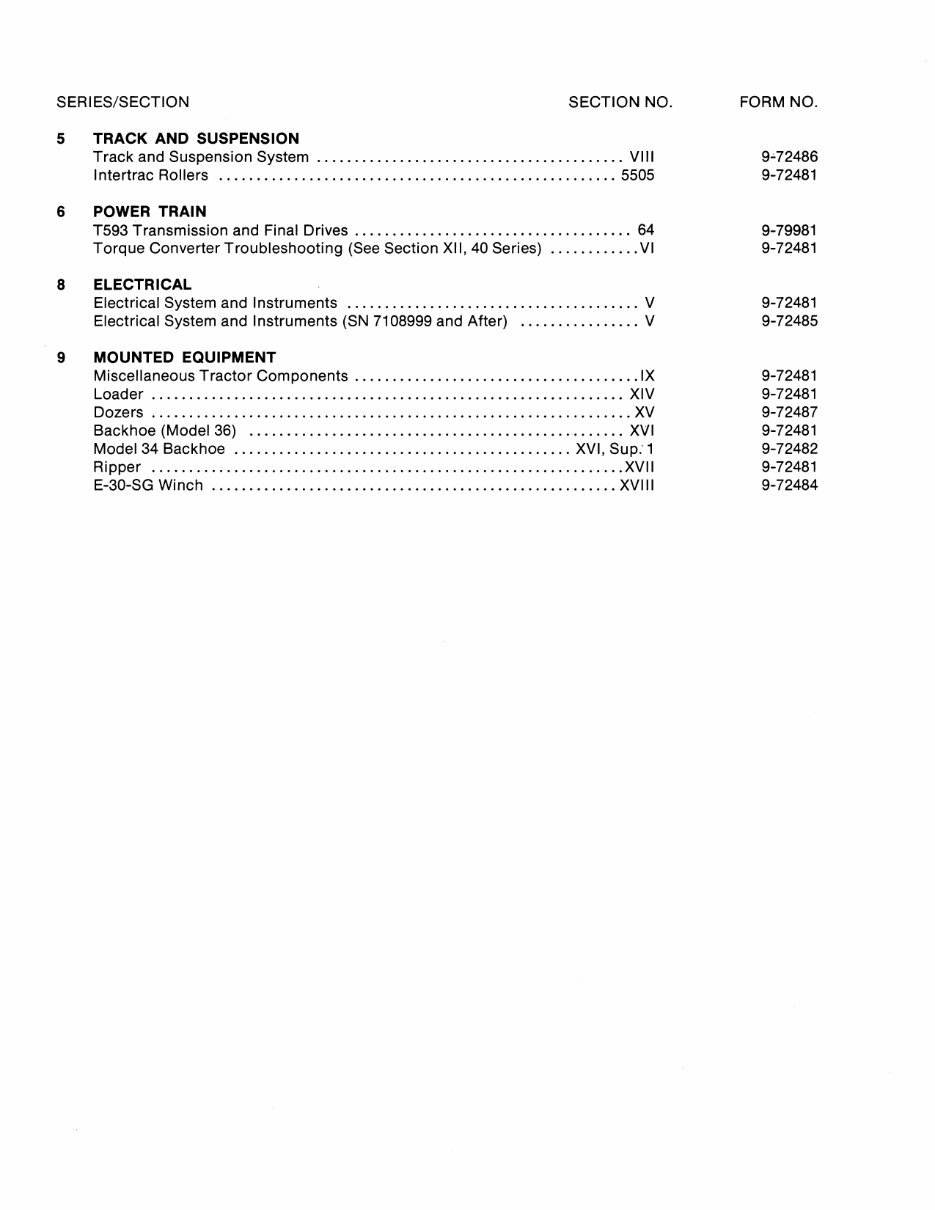
5 TRACK AND SUSPENSION
Track and Suspension System ......................................... VIII
I ntertrac Rollers ..................................................... 5505
6 POWER TRAIN
T593 Transmission and Final Drives ..................................... 64
Torque Converter Troubleshooting (See Section XII, 40 Series) ............ VI
8 ELECTRICAL
Electrical System and Instruments ....................................... V
Electrical System and Instruments (SN 7108999 and After) ................ V
9 MOUNTED EQUIPMENT
Miscellaneous Tractor Components ...................................... IX
Loader ............................................................... XIV
Dozers ................................................................ XV
Backhoe (Model 36) .................................................. XVI
Model 34 Backhoe ............................................. XVI, Sup: 1
Ripper ............................................................... XVII
E-30-SG Winch ...................................................... XVIII
FORM NO.
9.;.72486
9-72481
9-79981
9-72481
9-72481
9-72485
9-72481
9-72481
9-72487
9-72481
9-72482
9-72481
9-72484
Section
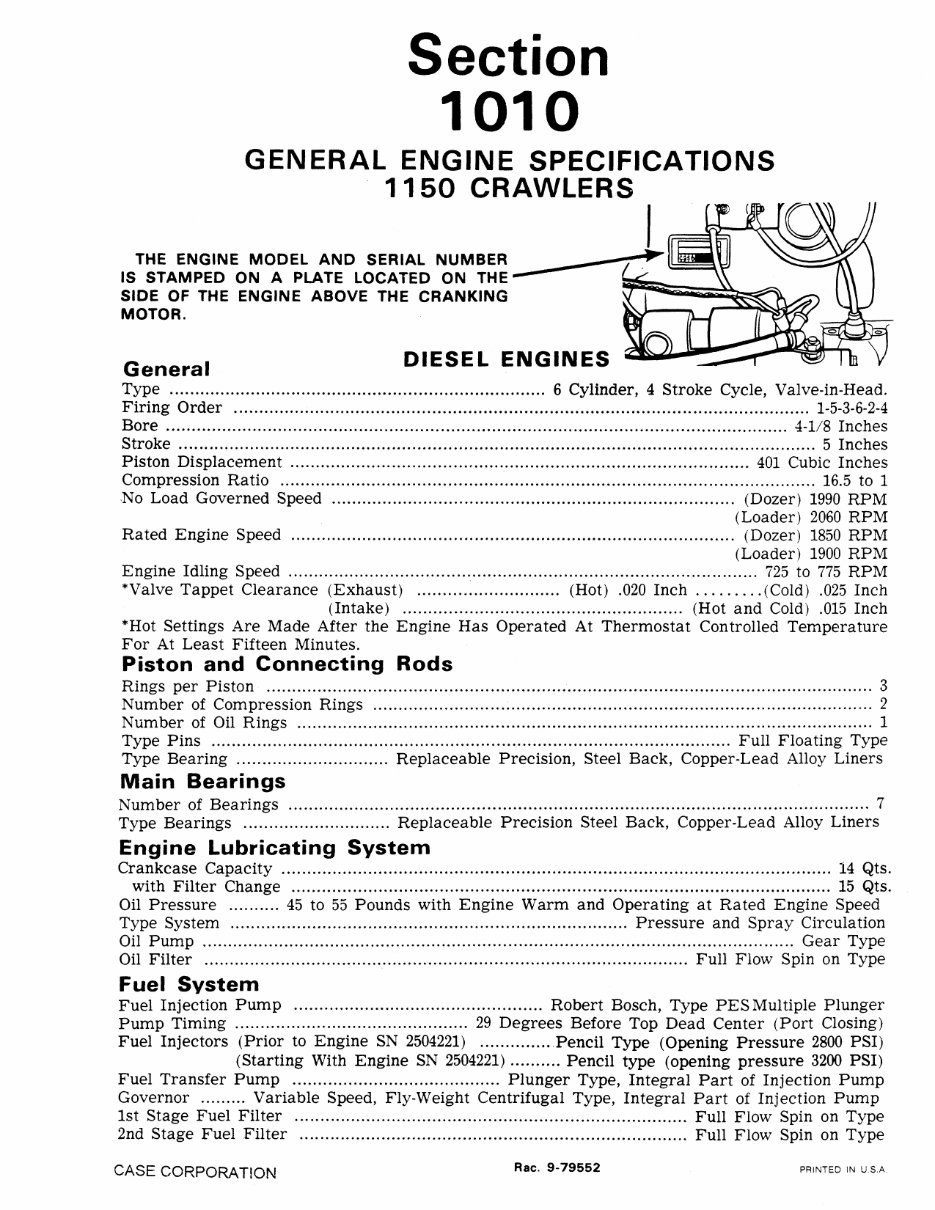
1010
GENERAL ENGINE SPECIFICATIONS
1150 CRAWLERS
THE ENGINE MODEL AND SERIAL NUMBER ___ ----/~ ~~
IS STAMPED ON A PLATE LOCATED ON THE-
SIDE OF THE ENGINE ABOVE THE CRANKING
MOTOR.
General
DIESEL ENGINES
Type .......................................................................... 6 Cylinder, 4 Stroke Cycle, Valve-in-Head.
Firing Order ................................................................................................................. 1-5-3-6-2-4
Bore .......................................................................................................................... 4-1/8 Inches
Stroke ............................................................................................................................. 5 Inches
Piston Displacement .......................................................................................... 401 Cubic Inches
Compression Ratio ......................................................................................................... 16.5 to 1
No Load Governed Speed ............................................................................... (Dozer) 1990 RPM
(Loader) 2060 RPM
Rated Engine Speed ....................................................................................... (Dozer) 1850 RPM
(Loader) 1900 RPM
Engine Idling Speed ............................................................................................ 725 to 775 RPM
"Valve Tappet Clearance (Exhaust) ............................ (Hot) .020 Inch ......... (Cold) .025 Inch
(Intake) ....................................................... (Hot and Cold) .015 Inch
*'Hot Settings Are Made After the Engine Has Operated At Thermostat Controlled Temperature
For At Least Fifteen Minutes.
Piston and Connecting Rods
Rings per Piston ......................................................................................... ..... .. .. .. ................... 3
Number of Compression Rings .................................................................................................. '2
Number of Oil Rings ................................................................................................................. 1
Type Pins ...................................................................................................... Full Floating Type
Type Bearing .............................. Replaceable Precision, Steel Back, Copper-Lead Alloy Liners
Main Bearings
Number of Bearings .................................................................................................................. 7
Type Bearings ............................. Replaceable Precision Steel Back, Copper-Lead Alloy Liners
Engine Lubricating System
Crankcase Capacity ............................................................................................................ 14 Qts.
with Filter Change .......................................................................................................... 15 Qts.
Oil Pressure .......... 45 to 55 Pounds with Engine Warm and Operating at Rated Engine Speed
Type System .............................................................................. Pressure and Spray Circulation
Oil Pump .................................................................................................................... Gear Type
Oil Filter ............................................................................................... Full Flow Spin on Type
Fuel System
Fuel Injection Pump ................................................. Robert Bosch, Type PES Multiple Plunger
Pump Timing .............................................. 29 Degrees Before Top Dead Center (Port Closing)
Fuel Injectors (Prior to Engine SN 2504221) .............. Pencil Type (Opening Pressure 2800 PSI)
(Starting With Engine SN 2504221) .......... Pencil type (opening pressure 3200 PSI)
Fuel Transfer Pump ......................................... Plunger Type, Integral Part of Injection Pump
Governor ......... Variable Speed, Fly-Weight Centrifugal Type, Integral Part of Injection Pump
1st Stage Fuel Filter ............................................................................. Full Flow Spin on Type
2nd Stage Fuel Filter ............................................................................ Full Flow Spin on Type
CASE CORPORATION
Rae. 9-79552 PRINTED IN U.S.A.

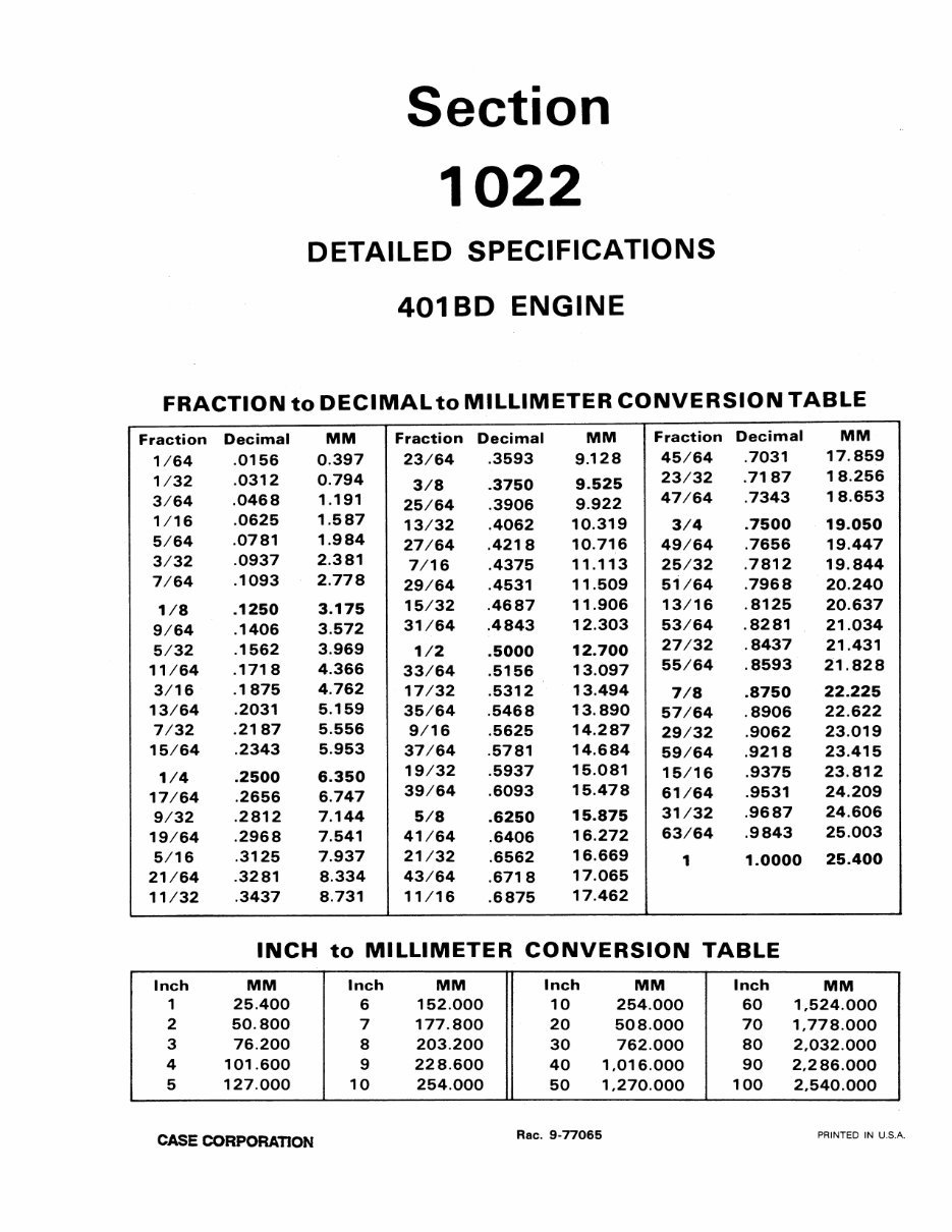
Section
1022
DETAILED SPECIFICATIONS
401 BD ENGINE
FRACTION to DECIMAL to MILLIMETER CONVERSION TABLE
Fraction Decimal MM Fraction Decimal MM Fraction Decimal MM
1/64 .0156 0.397 23/64 .3593 9.128 45/64 .7031 17.859
1/32 .0312 0.794
3/8 .3750 9.525
23/32 .7187 18.256
3/64 .0468 1.191
25/64 .3906 9.922
47/64 .7343 18.653
1/16 .0625 1.587
13/32 .4062 10.319 3/4 .7500 19.050
5/64 .0781 1.984
27/64 .4218 10.716 49/64 .7656 19.447
3/32 .0937 2.381
7/16 .4375 11.113 25/32 .7812 19.844
7/64 .1093 2.778
29/64 .4531 11.509 51/64 .7968 20.240
1/8 .1250 3.175
15/32 .4687 11.906 13/16 .8125 20.637
9/64 .1406 3.572
31/64 .4843 12.303 53/64 .8281 21.034
5/32 .1562 3.969
1/2 .5000 12.700
27/32 .8437 21.431
11/64 .1718 4.366
33/64 .5156 13.097
55/64 .8593 21.828
3/16 .1875 4.762
17/32 .5312 13.494
7/8 .8750 22.225
13/64 .2031 5.159
35/64 .5468 13.890
57/64 .8906 22.622
7/32 .2187 5.556
9/16 .5625 14.287
29/32 .9062 23.019
15/64 .2343 5.953
37/64 .5781 14.684
59/64 .9218 23.415
1/4 .2500 6.350
19/32 .5937 15.081
15/16 .9375 23.812
17/64 .2656 6.747
39/64 .6093 15.478
61/64 .9531 24.209
9/32 .2812 7.144 5/8 .6250 15.875
31/32 .9687 24.606
19/64 .2968 7.541 41/64 .6406
16.272
63/64 .9843 25.003
5/16 .3125 7.937 21/32 .6562 16.669
1 1.0000 25.400
21/64 .3281 8.334 43/64 .6718
17.065
11/32 .3437 8.731 11/16 .6875
17.462
INCH to MILLIMETER CONVERSION TABLE
Inch MM Inch MM Inch MM Inch MM
1 25.400 6 152.000 10 254.000 60 1,524.000
2 50.800 7 177.800 20 508.000 70 1,778.000
3 76.200 8 203.200 30 762.000 80 2,032.000
4 101.600 9 228.600 40 1.016.000 90 2,286.000
5 127.000 10 254.000 50 1,270.000 100 2,540.000
CASE CORPORA nON
Rae. 9-77065 PRINTED IN U.S.A.
1022-2
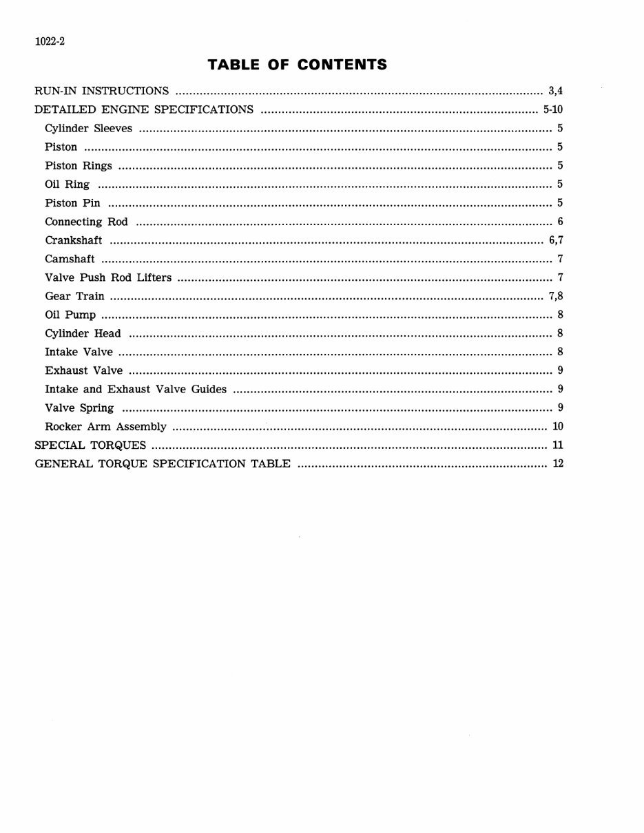
TABLE OF CONTENTS
RUN-IN INSTRUCTIONS .......................................................................................................... 3,4
DETAILED ENGINE SPECIFICATIONS ................................................................................ 5-10
Cylinder Sleeves ....................................................................................................................... 5
Piston ....................................................................................................................................... 5
Piston Rings ............................................................................................................................. 5
Oil Ring ................................................................................................................................... 5
Piston Pin .............................................................................................................................. .. 5
Connecting Rod ........................................................................................................................ 6
Crankshaft ............................................................................................................................. 6,7
Camshaft .................................................................................................................................. 7
Valve Push Rod Lifters ............................................................................................................ 7
Gear Train ...... ... ........ ... ... ... ........ ...... ....... ........... ........... ...... ..... ............ .... .... ..... .... ...... .......... 7,8
Oil Pump .................................................................................................................................. 8
Cylinder Head .......................................................................................................................... 8
Intake Valve ............................................................................................................................. 8
Exhaust Valve .......................................................................................................................... 9
Intake and Exhaust Valve Guides ............................................................................................ 9
Valve Spring ............................................................................................................................ 9
Rocker Arm Assembly................. ............. ............. ........ ... ......... .................... .... .... ......... ...... ... 10
SPECIAL TORQUES .................................................................................................................. 11
GENERAL TORQUE SPECIFICATION TABLE ...................................................... .................. 12
1022-3
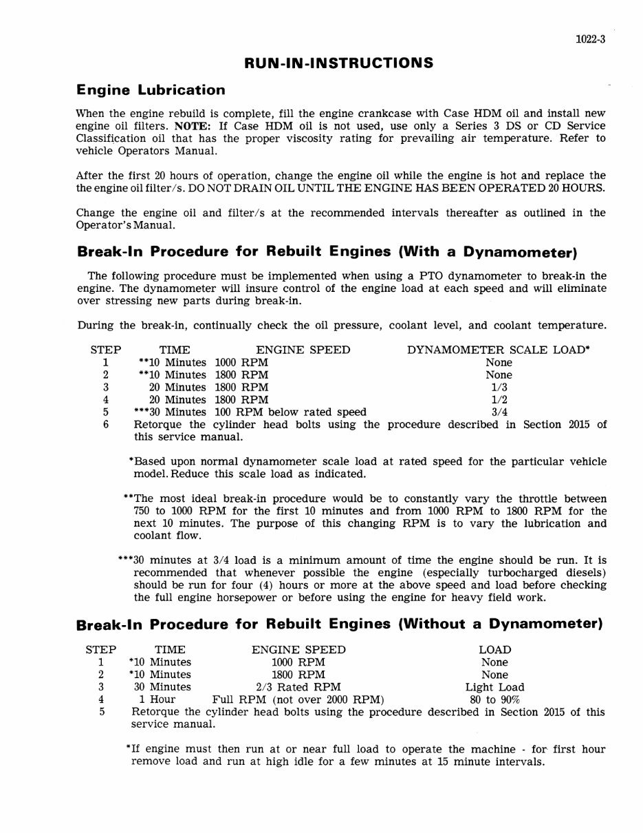
RUN-IN-INSTRUCTIONS
Engine Lubrication
When the engine rebuild is complete, fill the engine crankcase with Case HDM oil and install new
engine oil filters. NOTE: If Case HDM oil is not used, use only a Series 3 DS or CD Service
Classif~cation oil that has the proper viscosity rating for prevailing air temperature. Refer to
vehicle Operators Manual.
After the first 20 hours of operation, change the engine oil while the engine is hot and replace the
the engine oil filter Is. DO NOT DRAIN OIL UNTIL THE ENGINE HAS BEEN OPERA TED 20 HOURS.
Change the engine oil and filterls at the recommended intervals thereafter as outlined in the
Operator's Manual.
Break-In Procedure for Rebuilt Engines (With a Dynamometer)
The following procedure must be implemented when using a PTO dynamometer to break-in the
engine. The dynamometer will insure control of the engine load at each speed and will eliminate
over stressing new parts during break-in.
During the break-in, continually check the oil pressure, coolant level, and coolant temperature.
STEP
1
TIME ENGINE SPEED
"10 Minutes 1000 RPM
DYNAMOMETER SCALE LOAD*'
None
2
3
4
5
6
"10 Minutes 1800 RPM
20 Minutes 1800 RPM
20 Minutes 1800 RPM
"*'30 Minutes 100 RPM below rated speed
Retorque the cylinder head bolts using the
this service manual.
None
1/3
1/2
3/4
procedure described in Section 2015 of
*'Based upon normal dynamometer scale load at rated speed for the particular vehicle
model. Reduce this scale load as indicated.
"The most ideal break-in procedure would be to constantly vary the throttle between
750 to 1000 RPM for the first 10 minutes and from 1000 RPM to 1800 RPM for the
next 10 minutes. The purpose of this changing RPM is to vary the lubrication and
coolant flow.
"*'30 minutes at 3/4 load is a minimum amount of time the engine should be run. It is
recommended that whenever possible the engine (especially turbocharged diesels)
should be run for four (4) hours or more at the above speed and load before checking
the full engine horsepower or before using the engine for heavy field work.
Break-In Procedure for Rebuilt Engines (Without a Dynamometer)
STEP
1
2
3
4
5
TIME ENGINE SPEED LOAD
*'10 Minutes 1000 RPM None
*'10 Minutes 1800 RPM None
30 Minutes 213 Rated RPM Light Load
1 Hour Full RPM (not over 2000 RPM) 80 to 90%
Retorque the cylinder head bolts using the procedure described in Section 2015 of this
service manual.
*'If engine must then run at or near full load to operate the machine - for· first hour
remove load and run at high idle for a few minutes at 15 minute intervals.
1022-4
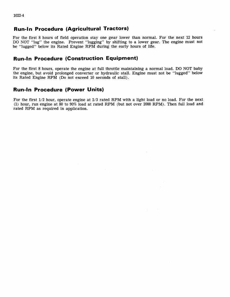
Run-I n Procedure (Agricultural Tractors)
For the first 8 hours of field operation stay one gear lower than normal. For the next 12 hours
DO NOT "lug" the engine. Prevent "lugging" by shifting to a lower gear. The engine must not
be "lugged" below its Rated Engine RPM during the early hours of life.
Run-In Procedure (Construction Equipment)
For the first 8 hours, operate the engine at full throttle maintaining a normal load. DO NOT baby
the engine, but avoid prolonged converter or hydraulic stall. Engine must not be "lugged" below
its Rated Engine RPM (Do not exceed 10 seconds of stall).
Run-In Procedure (Power Units)
For the first 1/2 hour, operate engine at 2/3 rated RPM with a light load or no load. For the next
(1) hour, run engine at 80 to 90% load at rated RPM (but not over 2000 RPM). Then full load and
rated RPM as required in application.
1022-5
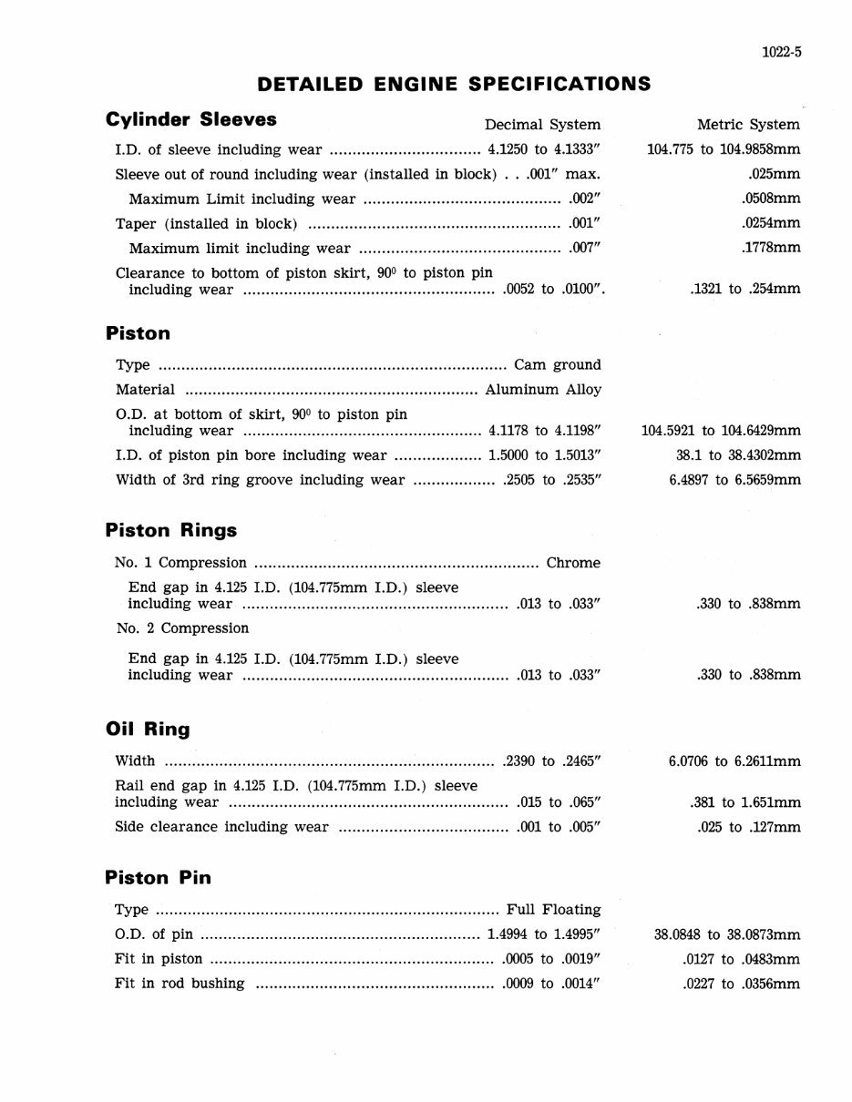
DETAILED ENGINE SPECIFICATIONS
Cylinder Sleeves
Decimal System
LD. of sleeve including wear ....... ........... ... ............ 4.1250 to 4.1333"
Sleeve out of round including wear (installed in block) ... 001" max.
Maximum Limit including wear .... ....... ........ ........... ..... ..... ... .002"
Taper (installed in block) ........................................................ 001"
Maximum limit including wear ............................................. 007"
Clearance to bottom of piston skirt, 90
0
to piston pin
including wear ....................................................... .0052 to .0100".
Piston
Type ..... ...... ...... ...... .................. ........ ................... ........ Cam ground
Material .. , ............................................................. Aluminum Alloy
O.D. at bottom of skirt, 90
0
to piston pin
including wear .................................................... 4.1178 to 4.1198"
LD. of piston pin bore including wear ................... 1.5000 to 1.5013"
Width of 3rd ring groove including wear . .... ........ ..... .2505 to .2535"
Piston Rings
No.1 Compression ............................................................... Chrome
End gap in 4.125 LD. (104.775mm LD.) sleeve
including wear ........................................................... 013 to .033"
No. 2 Compression
End gap in 4.125 LD. (104.775mm LD.) sleeve
including wear .............. ....... ................................ ..... .013 to .033"
Oil Ring
Width ...................................................... ; .................. 2390 to .2465"
Rail end gap in 4.125 LD. (104.775mm LD.) sleeve
including wear ........ .............. ..... .................................. .015 to .065"
Side clearance including wear ..................................... .001 to .005"
Piston Pin
Type ........................................................................... Full Floating
O.D. of pin .... ..................... ... ..... ............... ............. 1.4994 to 1.4995"
Fit in piston .. ... ........................ ............. ..... ............... .0005 to .0019"
Fit in rod bushing ..................................................... 0009 to .0014"
Metric System
104.775 to 104.9858mm
.025mm
.0508mm
.0254mm
.1778mm
.1321 to .254mm
104.5921 to 104.6429mm
38.1 to 38.4302mm
6.4897 to 6.5659mm
.330 to .838mm
.330 to .838mm
6.0706 to 6.2611mm
.381 to 1.651mm
.025 to .127mm
38.0848 to 38.0873mm
.0127 to .0483mm
.0227 to .0356mm
You're Reading a Preview
What's Included?
Fast Download Speeds
Online & Offline Access
Access PDF Contents & Bookmarks
Full Search Facility
Print one or all pages of your manual
$37.99
CASE 1150 Crawler Service Repair Workshop Manual
Viewed 14 Times Today

What's Included?
Fast Download Speeds
Online & Offline Access
Access PDF Contents & Bookmarks
Full Search Facility
Print one or all pages of your manual
$37.99

Secure transaction
What's Included?
Fast Download Speeds
Online & Offline Access
Access PDF Contents & Bookmarks
Full Search Facility
Print one or all pages of your manual
Description
This is the complete factory service repair workshop manual for the CASE 1150 Crawler. It has easy-to-read text sections with top quality diagrams and instructions, making it useful for both professional mechanics and DIY enthusiasts. The manual covers every single detail on your machine, providing step-by-step instructions based on the complete disassembly of the machine.
The Service Repair Manual Covers:
- General
- Engines
- Fuel System
- Hydraulics
- Tracks And Suspension System
- Power Train
- Electrical System
- Mounting Equipment
- And More......
File Format: .PDF
Compatibility: All Versions of Windows & Mac
Language: English
Requirements: Adobe Reader & WinZip
All pages are printable, saving you money on postage and packaging. It is great to have for maintaining your vehicle.


