

UNIC HYDRAULIC CRANE
MODEL
WMURVseries200107A
PRINTED IN JAPAN
HEAD OFFICE : Center Bldg., 3-12, Higashishinagawa 2-chome,
Shinagawa-ku, Tokyo 140-0002, JAPAN
WORK SHOP
MANUAL


INTRODUCTION
This technical instruction manual describes the construction of the UNIC URV SERIES crane and mainte-
nance procedures for those who engage in its maintenance.
Please carefully read the manual to acquire the proper maintenance skills and provide efficient, speedy, cor-
rect service that are essential to customer trust. In this way, UNIC truck crane will be able to deliver their
superb performance and be kept in satisfactory operating condition.
It is recommended that separate parts list be referred to together with this manual.
Technical Section, Service Department
FURUKAWA UNIC CORPORATION

CONTENTS
1. GENERAL VIEW ......................................................................................................................... 1
2. BOOM
2. 1. 2-Section Boom .......................................................................................................................... 2
(1) Construction of boom and operation......................................................................................... 2
(2) Boom 1, 2 front side section in detail ........................................................................................ 3
2. 2. 3-Section Boom .......................................................................................................................... 4
(1) Construction, operation, and disassembling procedures ....................................................... 4
(2) Boom 2, 3 front side section in detail ........................................................................................ 5
(3) Boom disassembly procedures ................................................................................................. 6
2. 3. 4-Section Boom .......................................................................................................................... 8
(1) Construction of boom and operation......................................................................................... 8
(2) How boom-top sheave is mounted ............................................................................................ 9
(3) Installation procedures for slide plate and guide ..................................................................... 10
(4) Boom 3, 4 front side section in detail ........................................................................................ 11
(5) Boom 2, 3 rear side section in detail ......................................................................................... 12
(6) Boom 3, 4 rear side section in detail ......................................................................................... 13
(7) How to disassemble 4-section boom of URV-series ................................................................ 14
2. 4. 5-Section Boom .......................................................................................................................... 18
(1) Simultaneous telescoping boom 4 and boom 5 ....................................................................... 18
(2) Boom 4, 5 front side section in detail ........................................................................................ 19
(3) Boom 3, 4 rear side section in detail ......................................................................................... 20
3. TELESCOPING CYLINDER
3. 1 2-section boom (Single cylinder) operation.............................................................................. 21
(1) When telescoping cylinder extends........................................................................................... 21
(2) When telescoping cylinder retracts ........................................................................................... 22
3. 2 3-section boom (Dual cylinder) operation................................................................................. 23
(1) When telescoping cylinder extends........................................................................................... 23
(2) When telescoping cylinder retracts ........................................................................................... 24
(3) When telescoping cylinder 2 extends........................................................................................ 25
(4) When telescoping cylinder 2 retracts ........................................................................................ 26
3. 3 4-section boom (Dual cylinder) operation................................................................................. 27
(1) When telescoping cylinder 1 extends........................................................................................ 27
(2) When telescoping cylinder 1 retracts ........................................................................................ 28
(3) When telescoping cylinder 2 extends........................................................................................ 29
(4) When telescoping cylinder 2 retracts ........................................................................................ 30
3. 4 5-section boom (Triple cylinder) operation............................................................................... 31
(1) When telescoping cylinder 1 extends........................................................................................ 31
(2) When telescoping cylinder 1 retracts ........................................................................................ 32
(3) When telescoping cylinder 2 extends........................................................................................ 33
(4) When telescoping cylinder 2 retracts ........................................................................................ 34
(5) When telescoping cylinder 3 extends........................................................................................ 35
(6) When telescoping cylinder 3 retracts ........................................................................................ 36
3. 5 3-section boom (Dual telescoping cylinder) disassembly procedures .................................. 37
(1) Disassembly procedures for telescoping cylinder 1................................................................ 38
(2) Disassembly procedures for telescoping cylinder 2................................................................ 40
(3) Inspection ..................................................................................................................................... 41
(4) Adjusting procedures for selector valve with adjusting bolt .................................................. 41
3. 6 Function and working of cushion seal ...................................................................................... 42
(1) Flow of pressure oil when retracting ......................................................................................... 42
(2) Flow of pressure oil when extending......................................................................................... 43
3. 7 Cause of troubles and measures to be taken ........................................................................... 44

4. DERRICK CYLINDER
4. 1 Flow of oil when raising .............................................................................................................. 47
4. 2 Flow of oil when lowering ........................................................................................................... 48
5. OUTRIGGER
5. 1 Outrigger cylinder (URV230, V260, V290, V300, V340) ............................................................. 49
(1) Flow of oil when extending ......................................................................................................... 49
(2) Flow of oil when retracting.......................................................................................................... 50
5. 2 Construction of outrigger cylinder (URV370) ........................................................................... 51
5. 3 Construction of outrigger cylinder (URV500) ........................................................................... 52
5. 4 Construction of inner box........................................................................................................... 53
6. HOIST WINCH
6. 1 Construction of hoist winch and brake shoe adjusting procedures ...................................... 54
6. 2 Caution to be taken when reassembling hoist winch .............................................................. 55
6. 3 Cause of troubles and measures to be taken ........................................................................... 56
7. HOOK ............................................................................................................................................. 57
8. SLEWING
8. 1 Slewing reduction gear ............................................................................................................... 58
(1) Construction of slewing reduction gear .................................................................................... 58
(2) Caution to be taken when reassembling slewing reduction gear ........................................... 59
(3) Slewing reduction gear disassembling procedures ................................................................. 60
8. 2 Turn table mounting procedures ............................................................................................... 63
(1) Turn table mounting procedures ................................................................................................ 63
(2) Position of soft zone, tightening sequence of bolts and tightening torque ........................... 64
9. COLUMN
9. 1 Tightening torque for bolts fastening column and tightening order ...................................... 65
10. SWIVEL JOINT
10. 1 Construction of swivel joint and position of hoses ............................................................... 66
10. 2 Swivel joint assembling procedures ....................................................................................... 68
11. SLIP RING
11. 1 Construction of slip ring and its fitting position .................................................................... 69
12. CONTROL................................................................................................................................... 70
13. HYDRAULIC CIRCUIT DIAGRAM
13. 1 Hydraulic Circuit Diagram (URV230, URV260, URV290, URV340, URV370) ......................... 71
13. 2 Hydraulic Circuit Diagram (URV500) ....................................................................................... 72
14. CONYROL VALVE
14. 1 General view and specifications .............................................................................................. 73
14. 2 How oil flows in control valve .................................................................................................. 74
14. 3 Relief valve ................................................................................................................................. 75
15. OVERWINDING ALARM
15. 1 Function of overwinding alarm and procedures for operation ............................................. 77
15. 2 General view .............................................................................................................................. 78
15. 3 Illustrated wiring diagram, overwinding alarm ....................................................................... 80
15. 4 Electric circuit diagram ............................................................................................................. 81
16. FILTERS (Suction Filter and Return Filter) ................................................................... 82
17. CYLINDERS, HOW TO PUNCH .......................................................................................... 83
18. TELESCOPING/DERRICK CYLINDER ASS’ Y, MEASURES TO
PREVENT FROM BEING LOOSENED.............. 84

19. INSPECTION PROCEDURES WHEN CYLINDER SINKS
19. 1 Inspection of telescoping cylinder (3-section or 4-section boom) ....................................... 86
19. 2 Inspection of derrick cylinder .................................................................................................. 87
19. 3 Inspection of outrigger cylinder ............................................................................................... 88
20. MAINTENANCE AND INSPECTION
20. 1 Inspection................................................................................................................................... 90
(1) Inspection before operation ........................................................................................................ 90
(2) Inspection of the slewing bearing mounting bolts ................................................................... 91
20. 2 Replacement .............................................................................................................................. 91
(1) Replacement of return filter ........................................................................................................ 91
(2) Replacement of wire rope (for winding up) ............................................................................... 92
(3) Replacement of expendable parts .............................................................................................. 96
21. LUBRICATION
21. 1 Precaution on lubrication ......................................................................................................... 97
(1) List of recommended lubricants................................................................................................. 98
(2) Lubrication chart .......................................................................................................................... 99
21. 2 Lubrication ................................................................................................................................. 100
(1) Replacement of hydraulic oil ...................................................................................................... 100
(2) Replacement of gear oil ............................................................................................................... 101
(3) Lubrication to slewing bearings ................................................................................................. 102
(3) Lubrication to wire rope for boom extension ............................................................................ 102
- 1 -
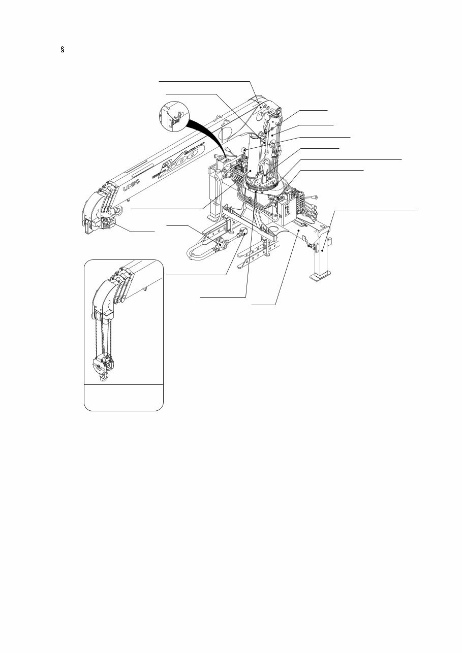
1. GENERAL VIEW
HOOK
HOIST WINCH
TERESCOPING CYLINDER
DRUM
COLUMN
LOAD GAUGE
SLIP RING
SLEWING REDUCTION GEAR
SLEWING MOTOR
OUTRIGGER CYLINDER
BASE
TURNTABLE
PTO
(POWER TAKE OUT)
DERRICK CYLINDER
PUMP
Hook on standard
specification
- 3 -
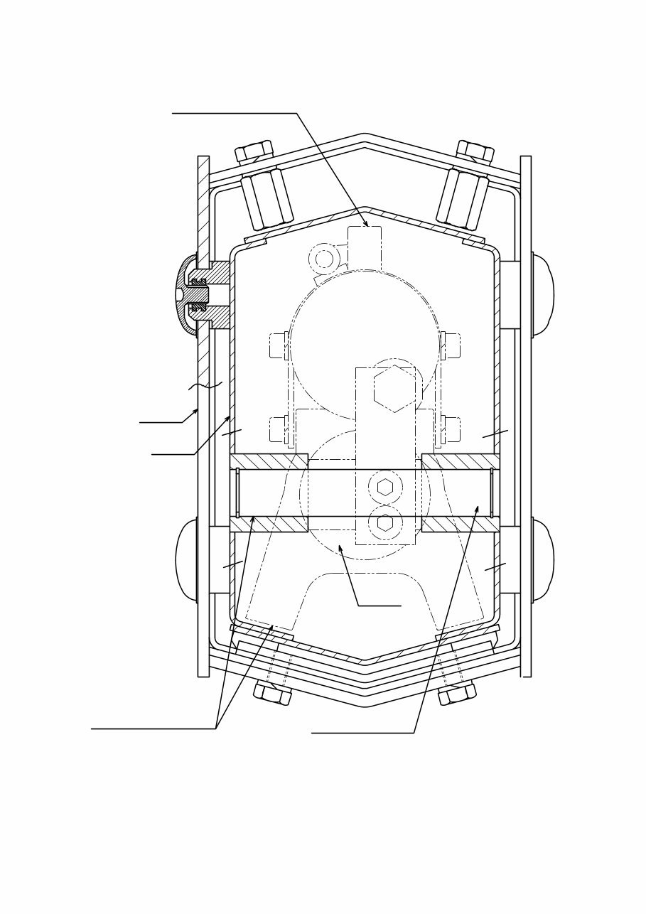
(2) Boom 1, 2 front side section in detail
Boom1
Boom2
Tele-cylinder Rod
Boom2
Conecting Pin
Tele Rod
- 5 -
(2) Boom 2, 3 front side section in detail
Tele1
Tele2
Tele2 Rod
Boom3
Conecting Pin
Boom3
Boom2
When assembling,
apply grease.
When assembling,
apply grease.
- 6 -
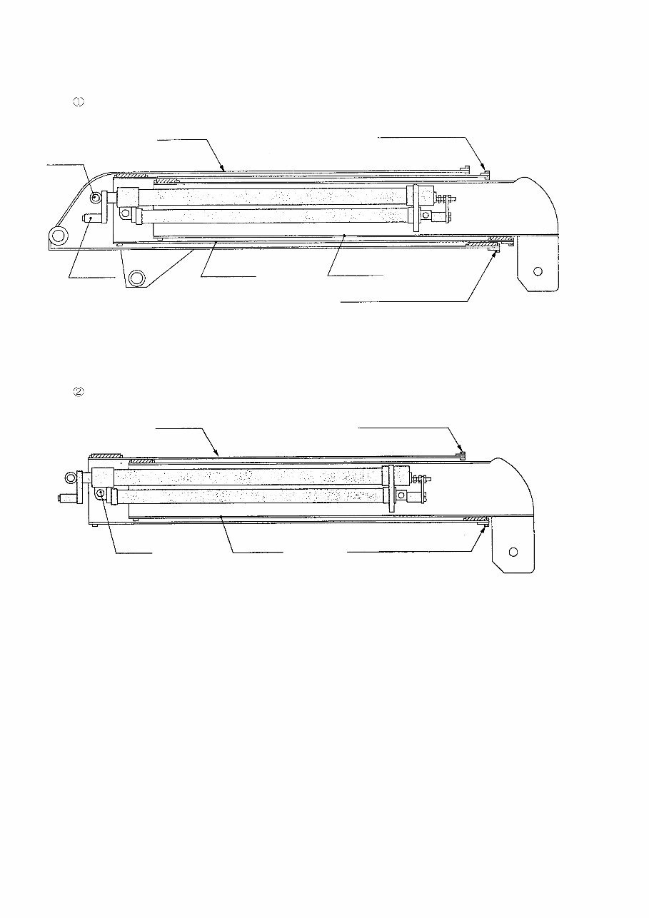
(3) Boom Disassembly Procedures
(1) 3-Section Boom
Pull out the booms (2) and (3) from the boom (1).
PIN (1)
JOINT
BOOM (2)
BOOM (1)
BOLT FOR GUIDE
BOLT FOR SLIDE PLATE
BOOM (3)
1. Remove the joint (for piping) of the telescoping cylinder.
2. Remove the slide plates (side and lower plates), and the guide.
3. Remove the pin (1) from the boom (1), and pull the booms (2) and (3) out of the boom (1).
Pull out the boom (3) from the boom (2).
PIN (2)
BOOM (2) BOLT FOR GUIDE
BOLT FOR SLIDE PLATE
BOOM (3)
1. Remove the slide plates (side and lower plates) and the guide.
2. Remove the pin (2) from the boom (2), and pull out the boom (3).
You're Reading a Preview
What's Included?
 Lifetime Access
Fast Download Speeds
Online & Offline Access
Access PDF Contents & Bookmarks
Full Search Facility
Print one or all pages of your manual
$41.99
UNIC Hydraulic CRANE URV Series Workshop Service Manual
Viewed 64 Times Today

What's Included?
Lifetime Access
Fast Download Speeds
Online & Offline Access
Access PDF Contents & Bookmarks
Full Search Facility
Print one or all pages of your manual
$41.99

Secure transaction
What's Included?
Lifetime Access
Fast Download Speeds
Online & Offline Access
Access PDF Contents & Bookmarks
Full Search Facility
Print one or all pages of your manual
Description
UNIC HYDRAULIC CRANE
MODEL URV series
- URV230
- URV260
- URV290
- URV300
- URV340
- URV370
- URV500
WORKSHOP MANUAL
INTRODUCTION
This technical instruction manual describes the construction of the UNIC URV SERIES crane and maintenance procedures for those who engage in its maintenance.


