

Furakawa F series hyd breaker. F6,F9,F12,F19,F22,F27,F35,F45
What's Included?
Fast Download Speeds
Online & Offline Access
Access PDF Contents & Bookmarks
Full Search Facility
Print one or all pages of your manual

F(L) - F109E
Hydraulic Breaker
SERIES
(F6,F9,F12,F19,F22,F27,F35,F45,F70)
INSTRUCTION MANUAL
WARNING
Inadvertent use of the breaker may cause serious
injury or death.
Operators and service personnel shall carefully read
this breaker operation manual to thoroughly
understand the details.
Read the operation manual for the carrier as well.


FOREWORD
This manual is composed of three sections, "SAFETY", "OPERATION", "INSPECTION /
MAINTENANCE" and explains the correct handling and daily checkup and repair when using the
breaker F-series.
For the excavator to mount on, refer to the instruction manual for the excavator.
Before using the breaker, be sure to read this manual and fully understand the operation, inspection
and repair.
In addition, some of the contents and illustrations in this manual are subject to change without notice.
"Carelessness and negligence" cause an accident.
"Safety first"
You have a key to safety !
WARNING
Check or repair the breaker erroneously.
If the breaker is used carelessly, an accident, which could result in serious
injury or death, will be caused.
• This manual should be kept near the excavator on which the breaker is
mounted and the user should read it before operation.
• Operator and maintenance service personnel shall read this manual
before operation.
• If this manual is lost or damaged or if you need it, order a new one from
your dealer.
• If the breaker is transferred, be sure to attach this manual to the breaker.
• This manual has been made according to the regulations of Japan. If it is
used abroad, follow the regulations of the country.

CONTENTS
SAFETY INFORMATION ................................................................................ 0 - 1
OUTLINE OF MACHINE ................................................................................ 0 - 2
LOCATION OF MODEL NAME AND SERIAL NO. ......................................... 0 - 3
LOCATION OF WARNING LABEL ................................................................. 0 - 4
Safety
SAFETY PRECAUTIONS ............................................................................... 1 - 1
Safety control............................................................................................................... 1 - 1
Precautions before and after starting the engine ......................................................... 1 - 6
Precautions for safe operation ..................................................................................... 1 - 8
Precautions for parking and stopping the machine .................................................... 1 - 18
Roadway transfer ...................................................................................................... 1 - 19
Precautions for maintenance ..................................................................................... 1 - 21
Operation
NAME OF COMPONENTS AND SPECIFICATIONS ...................................... 2 - 1
Name of components and specifications ..................................................................... 2 - 1
Standard specifications ................................................................................................ 2 - 2
FUNCTION OF EACH PART .......................................................................... 2 - 3
OUTSIDE DIMENSIONS ................................................................................ 2 - 9
Outside dimensions of hydraulic breaker ..................................................................... 2 - 9
Outside dimensions of side bracket ........................................................................... 2 - 10
Outside dimensions of T-box ..................................................................................... 2 - 12
Outside dimensions of Side plate .............................................................................. 2 - 15
TYPES OF RODS AND MAJOR APPLICATIONS ...........................................2 - 17
OIL HOSE PLUG AND CAP ............................................................................2 - 18
ATTACHING/DETACHING HYDRAULIC BREAKER .....................................2 - 19

Attaching hydraulic breaker ....................................................................................... 2 - 19
Detaching hydraulic breaker ...................................................................................... 2 - 23
OPERATION PROCEDURES (BREAKING) ..................................................2 - 25
Precautions for safe operation ................................................................................... 2 - 25
Breaking operation .................................................................................................... 2 - 26
Optimal thrust ............................................................................................................ 2 - 27
Direction of thrust ...................................................................................................... 2 - 28
Precautions for operation........................................................................................... 2 - 28
Storage after operation .............................................................................................. 2 - 32
LONG-TERM STORAGE ...............................................................................2 - 33
TROUBLESHOOTING ..................................................................................2 - 34
HYDRAULIC OIL ...........................................................................................2 - 36
Selection of hydraulic oil ............................................................................................ 2 - 36
Classification of hydraulic oil and grease ................................................................... 2 - 36
Oil temperature control .............................................................................................. 2 - 36
Oil contamination ....................................................................................................... 2 - 37
Inspection/Maintenance
MAINTENANCE, INSPECTION AND REPAIR ............................................... 3 - 1
Periodical inspection and repair ................................................................................... 3 - 1
Daily inspection / inspection and maintenance before operation ................................. 3 - 3
Tightening torque of each bolt ..................................................................................... 3 - 5
WEAR LIMIT DIMENSIONS FOR CONSUMABLE PARTS ...........................3 - 12
WHEN TO REPLACE ROD AND FRONT BUSH COVER .............................3 - 15
REPLACEMENT OF ROD .............................................................................3 - 16
Removing from side plate and side bracket ............................................................... 3 - 16
Removing from T-BOX............................................................................................... 3 - 20
Mounting on rod......................................................................................................... 3 - 23
CHARGING BACK HEAD WITH N2 GAS
AND INSPECTION OF CHARGE PRESSURE .............................................3 - 25
N2 gas charging tool assembly .................................................................................. 3 - 26
Inspection of charge pressure.................................................................................... 3 - 26
Charging back head with N2 gas ............................................................................... 3 - 27

N2 gas charging pressure for the back head ............................................................. 3 - 27
CHARGING THE ACCUMULATOR WITH N2 GAS
AND INSPECTION OF CHARGE PRESSURE .............................................3 - 28
N2 gas charging tool assembly .................................................................................. 3 - 29
Inspection of charge pressure.................................................................................... 3 - 29
Charging accumulator with N2 gas ............................................................................ 3 - 30
N2 gas charging pressure for accumulator ................................................................ 3 - 30
ADJUSTMENT ..............................................................................................3 - 31
Adjustment of the number of blows............................................................................ 3 - 31
Adjustment of valve adjuster ...................................................................................... 3 - 32
OPTION .........................................................................................................3 - 34
Stroke valve (F12-F45) .............................................................................................. 3 - 34
Installation of stroke remote controller kit (F12-F45) .................................................. 3 - 35
Auto grease unit ........................................................................................................ 3 - 36
Automatic greasing .................................................................................................... 3 - 37
Operation of forced greasing ..................................................................................... 3 - 37
Cartridge grease change ........................................................................................... 3 - 38
Fix front cover (F12-F45) ........................................................................................... 3 - 40
Hydraulic breaker for tunneling .................................................................................. 3 - 41
Hydraulic breaker for underwater operation ............................................................... 3 - 42
0 - 1
SAFETY PRECAUTIONS
Safety Symbols
Most accidents come from neglect of basic safety precautions or rules or pre-operation inspection or
maintenance. Those could be avoided if possible hazards are well understood and measures are
taken.
Before operation, be sure to read and understand operating instructions as well as safety precautions
in this manual.
Safety symbols in this manual are classified as follows:
DANGER
Indicates an extremely hazardous situation which, if not observed and handled
properly, will result in death or serious injury (risk of death or serious injury).
WARNING
Indicates a potentially hazardous situation which, if not observed and handled
properly, could result in death or serious injury (possibility of death or serious injury).
CAUTION
Indicates a potentially hazardous situation which, if not observed and handled
properly, may result in minor or moderate injury.
NOTICE
Indicates precautions related to personal safety or property.
Note
DANGER or WARNING should not be considered for property damage accidents
unless personal injury risk appropriate to these levels is also involved. CAUTION (and
NOTICE) is permitted for property -damage- only accidents.
Every message with safety symbols includes preventive measures to avoid danger.
We, Furukawa however, could not anticipate every possible hazard completely so safety precautions
are included in this manual as many as possible. Ensure your safety, strictly observing those safety
precautions.

0 - 2
OUTLINE OF MACHINE
Use Of The Breaker
Applications
This breaker is used to break or smash hard rocks, concrete slabs etc and to dig hard, sold ground in a mine,
quarry or construction site (road, railroad, dam, demolition, preparation etc).
• Breaking by striking
• Demolishing by striking
• Digging by striking
WARNING
Do not use this breaker for any applications other than specified above.
Warming-up operation
This breaker is already factory-adjusted and checked before shipment. To maintain breaker's performance
and lengthen service life of breaker, operate breaker properly, considering the following:
• Perform warming-up operation for five minutes after starting engine.
• After warming-up, move boom, arm etc for about five minutes to raise the hydraulic oil temperature.
• When breaking or doing demolishing work, move the hand throttle to 'Mid' position and operate breaker
properly without putting overstress.
0 - 4
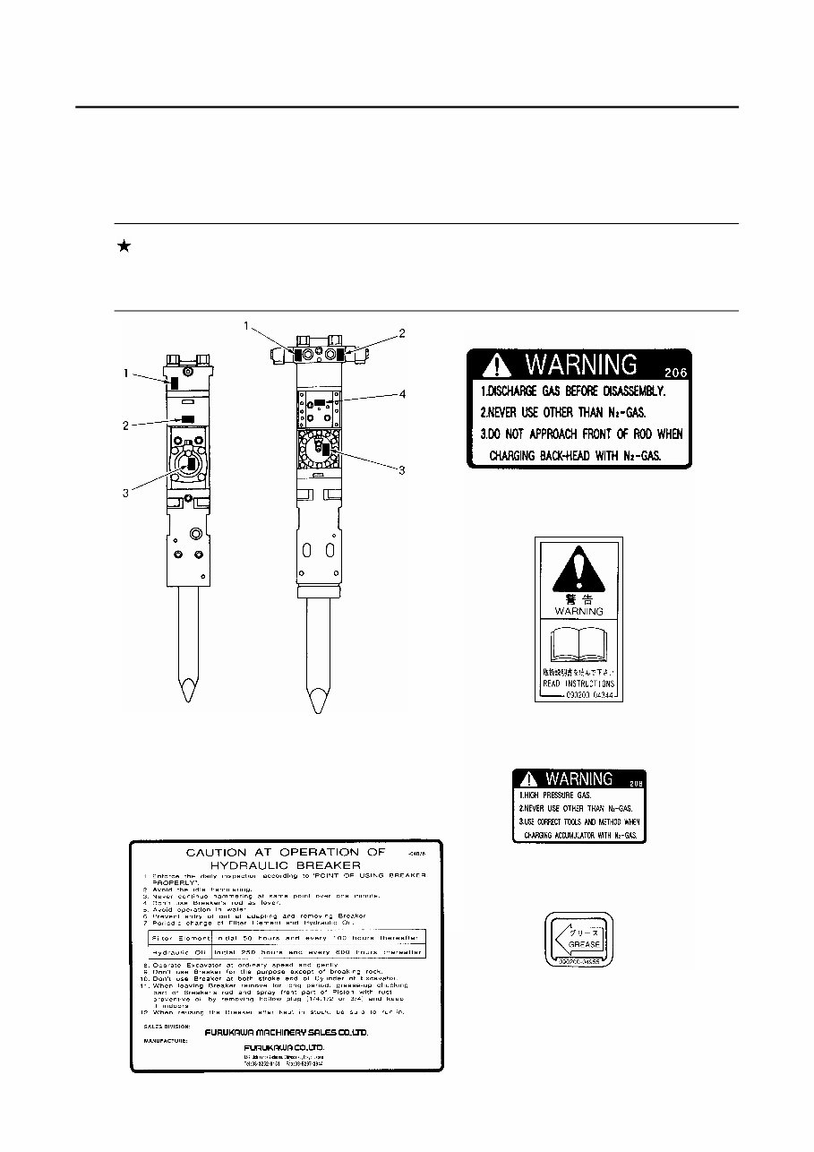
LOCATION OF WARNING LABEL
The warning labels show the instructions to prevent accidents caused by careless or wrong handling
during inspection and repair. Follow the instructions shown by the labels as well as those shown in
this manual.
NOTICE
If a warning label comes off or is damaged, stick it on again or replace it with a new
one.
1 090200-04206
2 090200-04344
(F6~F9) (F12~F70)
4 090200-04955
5 090200-04076
3 090200-04208
0 - 3
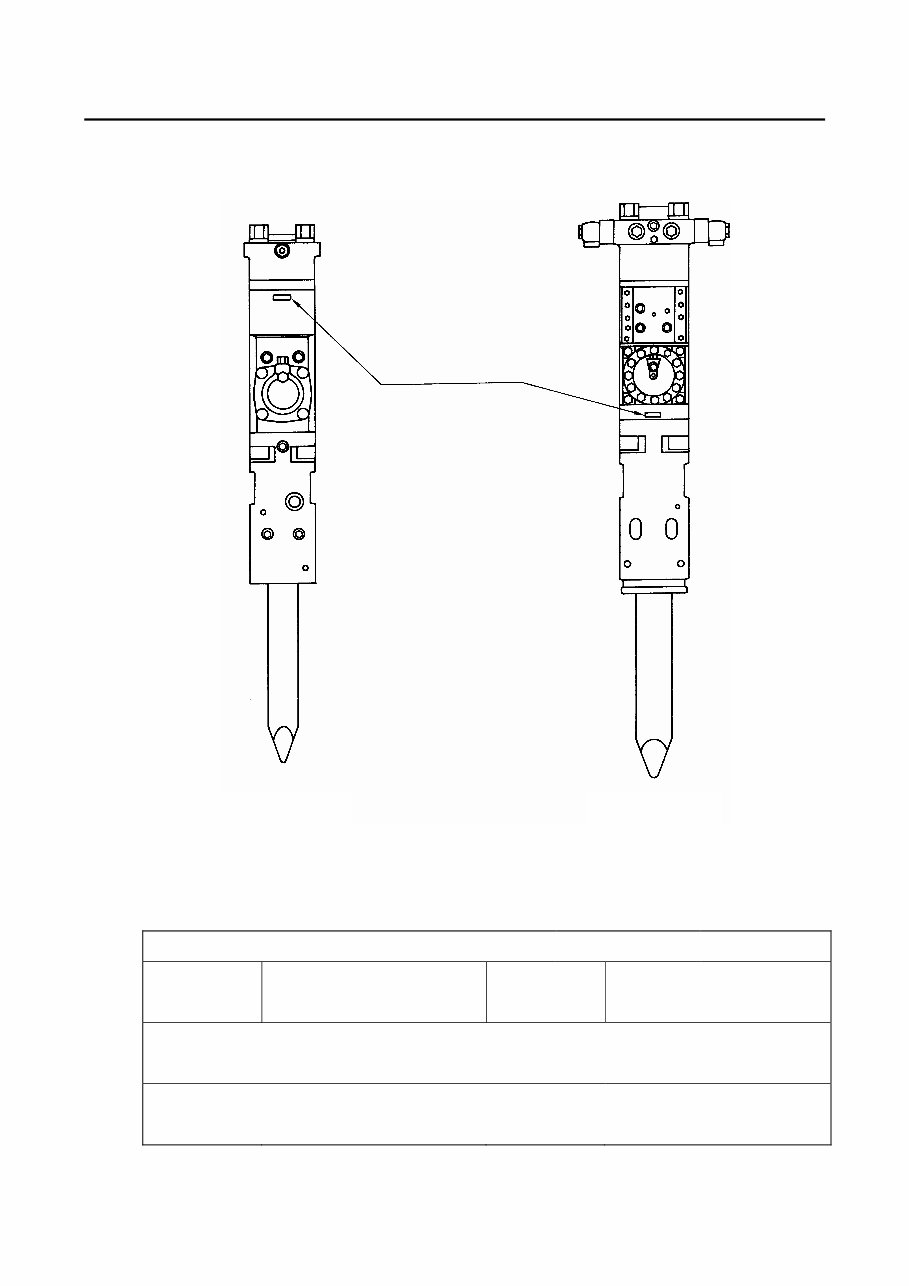
LOCATION OF MODEL NAME AND SERIAL NO.
• The model name and serial No. are stamped on the cylinder top of the breaker main body.
Advise your dealer of the model and serial No. when placing an order for parts or asking for repair.
*Swivel adapter isn't attached to F12.
Record your Breaker and Dealer details
Date of delivery: (Day) (month) (Year)
Model name Serial No.
Dealer
Address Phone
Service station
Address
Phone
* Part Nos. shown in this manual are subject to change without notice.
Location of machine No.
(F6 - F9) (F12 - F70)
You're Reading a Preview
What's Included?
Fast Download Speeds
Online & Offline Access
Access PDF Contents & Bookmarks
Full Search Facility
Print one or all pages of your manual
$31.99
Viewed 44 Times Today


Secure transaction
What's Included?
Fast Download Speeds
Online & Offline Access
Access PDF Contents & Bookmarks
Full Search Facility
Print one or all pages of your manual
$31.99
Furakawa F series hydraulic breaker instruction manual covers models F6, F9, F12, F19, F22, F27, F35, F45, and F70. This manual provides comprehensive guidance on maintenance, inspection, and repair procedures. With 128 pages of illustrated step-by-step instructions, it is a valuable resource for both professional mechanics and DIY enthusiasts.
The preview offers a glimpse of the manual's opening pages or a few sample pages. Please note that these pages are photocopies of the electronic file and may not fully reflect the high-quality content available in the complete manual. To view the preview, simply click the preview button located under the add to cart button.


