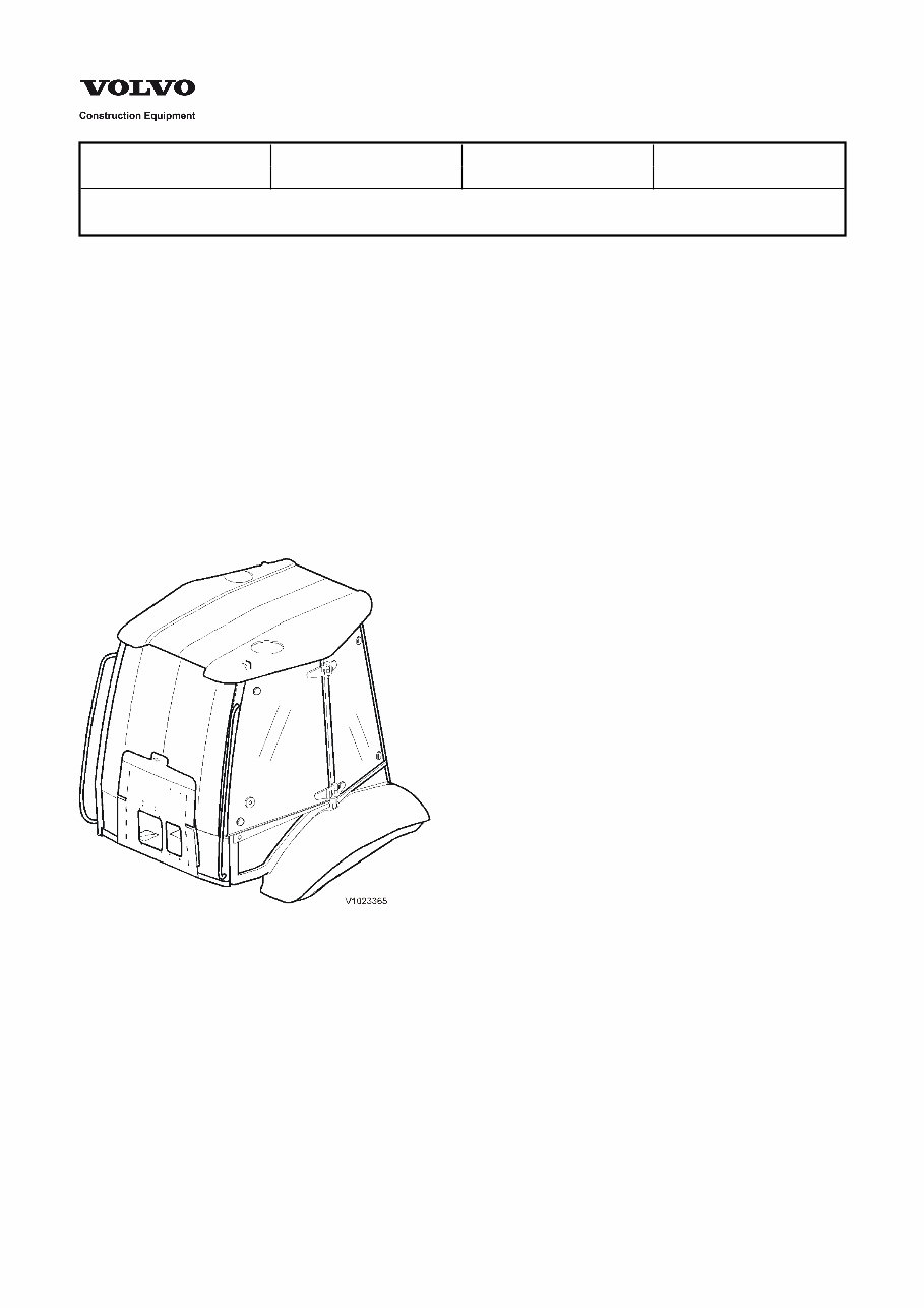
Service Information Document Title: Function Group: Information Type: Date: Cab, description 800 Service Information 2014/3/20 Profile: BHL, BL70 [GB] Cab, description The cab is approved as a protective cab according to FOPS and ROPS standards. FOPS is an abbreviation of Falling Objects Protective Structure (roof protection) and ROPS is an an abbreviation of Roll Over Protective Structure (roll over protection). Unauthorized modifications of the Roll Over Protective Structure (ROPS) Never make any unauthorized modifications to the ROPS, such as lowering the height of the roof, drilling, welding on fire extinguisher brackets, radio aerial brackets or other equipment. Such unauthorized modifications will affect the structural strength of the ROPS cab and will void the certification. All planned modifications must be reviewed in advance by our Engineering Department in order to determine whether the alteration can be made without affecting the certification. It is important that all persons in your organisation, including management, are made fully aware of these rules involving ROPS. If anyone in your company discovers that a certain machine was modified in a non-approved manner, your company must notify the customer and manufacturer in writing regarding which machine it was and how it was modified. Figure 1
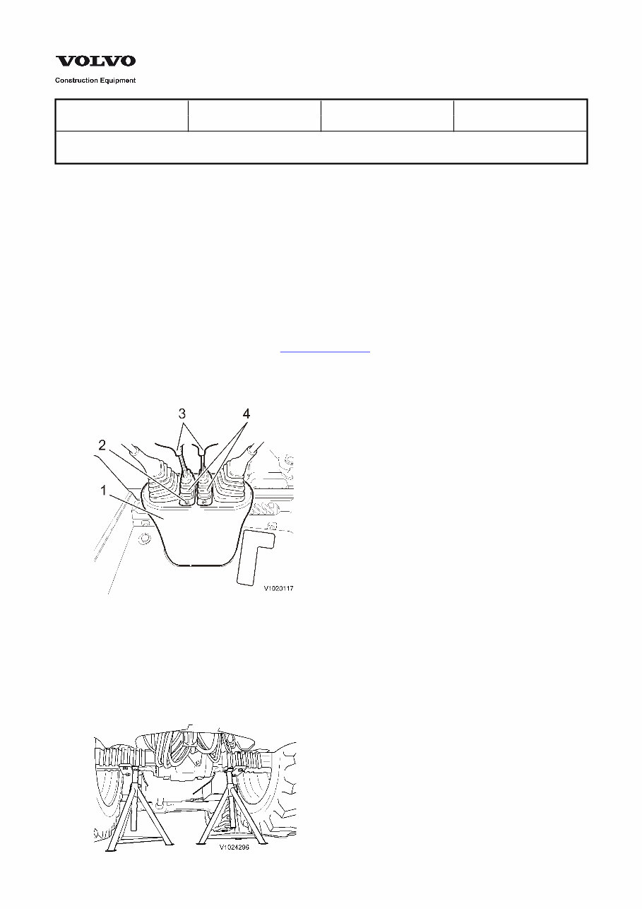
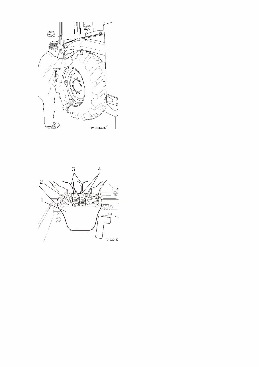
Service Information Document Title: Function Group: Information Type: Date: Cab, service position 800 Service Information 2014/3/20 Profile: BHL, BL70 [GB] Cab, service position Op nbr E1820, Stand Sling 6m 2 pcs. Shackle 4 pcs. Lifting eye M16, 4 pcs. 1. Place the machine in service position 2, see . 173 Service positions 2. Disconnect the battery disconnect switch. 3. Remove the lever handles and the screws to the casing. Figure 1 Backhoe controls 1. 2. 3. 4. Casing Screws Stabilizer levers Bellows 4. Lift up the rear of the machine and support the rear axle on stands.
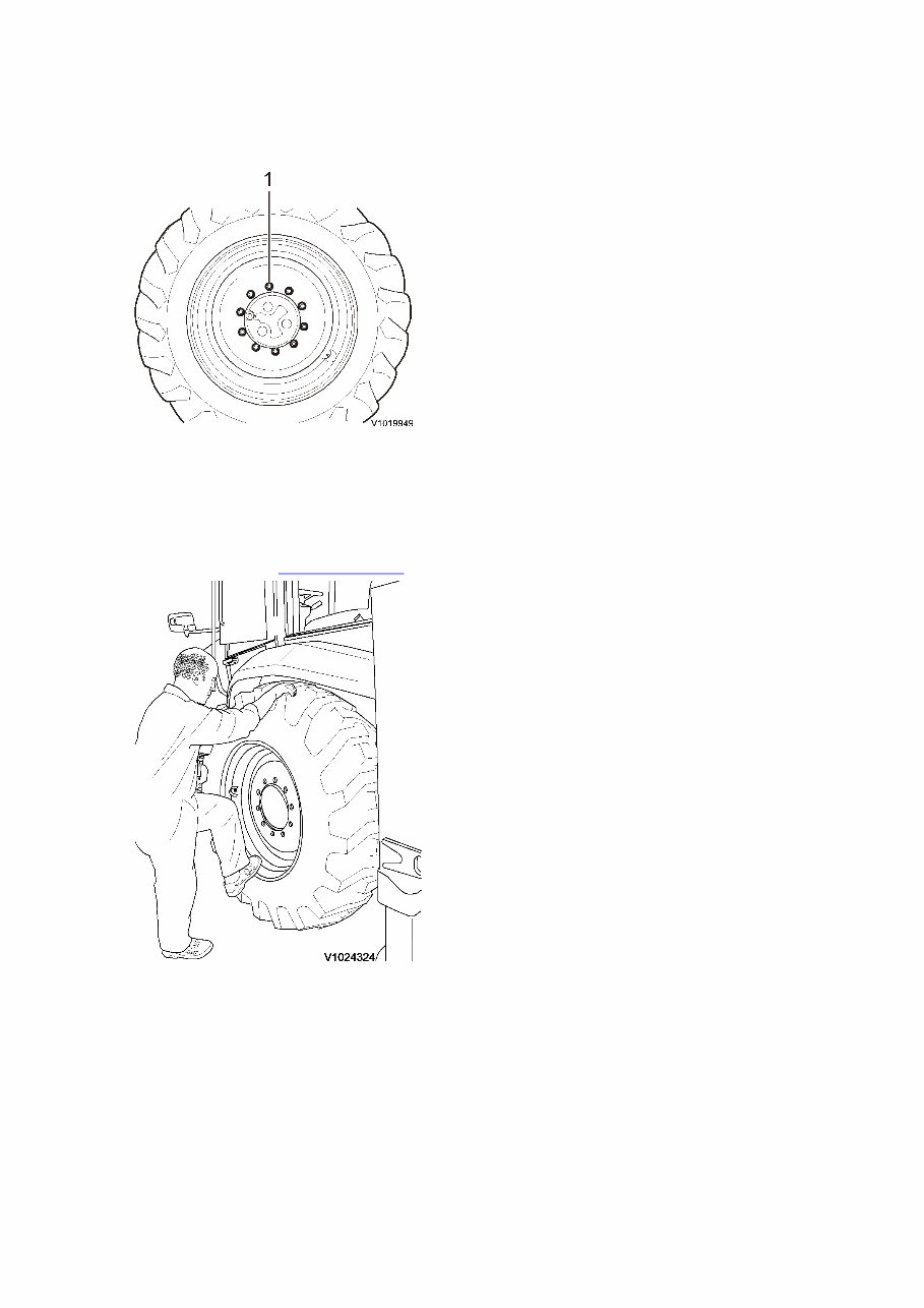
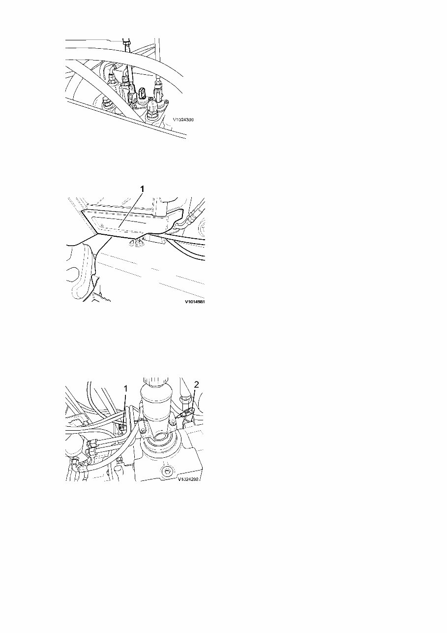
Figure 2 5. Remove the nuts and washers. Figure 3 1. Nut and washer 6. Remove the rear wheels. Rear wheel weight, see . 771 Wheels, weights Figure 4 7. If the machine is equipped with extendible dipper: Remove the extendible dipper linkage from the main control valve.
Figure 5 8. Remove the plastic cover. Figure 6 1. Plastic cover 9. If the machine is equipped with a manually operated parking brake: Remove the clevis pin and the pin and washer that attach the parking brake cable to the rear axle. Figure 7 1. 2. Pin and washer Clevis pin 10. Fold away the floor mat and remove the bolts to the front cab mountings. 11. Remove the bolts to the rear cab mounting.
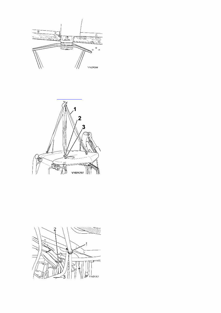
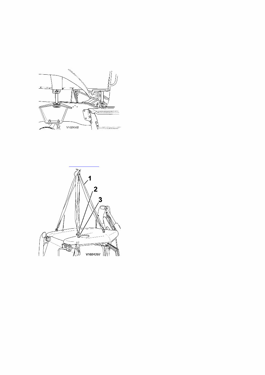
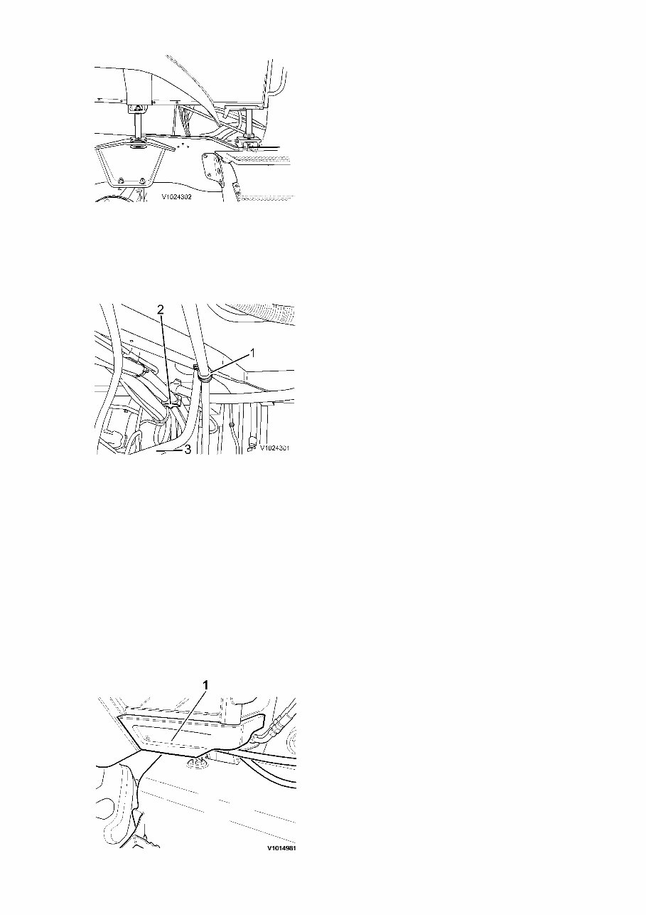
Figure 8 Rear cab mounting 12. Remove the screws and install M16 lifting eyes. Connect a shackle to each of the lifting eyes and attach two slings between shackle and a lifting device. Cab, weight: see . 800 Cab, weights Figure 9 1. 2. 3. Sling, 6 m Shackle Lifting eye, M16 13. Carefully lift up the cab approximately 100 mm (3.9 in) and remove the clamp and the bracket. NOTE! Place wooden blocks between the cab and frame to secure the cab. Figure 10
1. 2. 3. Clamp Bracket Gear lever (not on Powershift machines) 14. Carefully continue to lift up the cab another 100 mm (3.9 in) and install the four stands E1820. Tighten the bolts. NOTE! Make sure that hoses and cables not will be overstretched when lifting the cab. Figure 11 Installing 15. Connect sling and shackle to a lifting device and stretch the slings. Cab weights: see . 800 Cab, weights Figure 12 1. 2. 3. Sling, 6 m Shackle Lifting eye, M16 16. Remove the stands E1820.
Figure 13 17. Carefully lower the cab approximately 100 mm (3.9 in) and fit the clamp and the bracket. NOTE! Place wooden blocks between the cab and frame to secure the cab. Figure 14 1. 2. 3. Clamp Bracket Gear lever (not on Powershift machines) 18. Carefully lower the cab onto the cab mountings. NOTE! Make sure that no cables or hoses get pinched when lowering the cab. 19. Fit the bolts and tighten the cab mountings. Tightening torque, front and rear cab mountings: 380 Nm (280 lbf ft) Install the floor mat. 20. Fit the plastic cover.
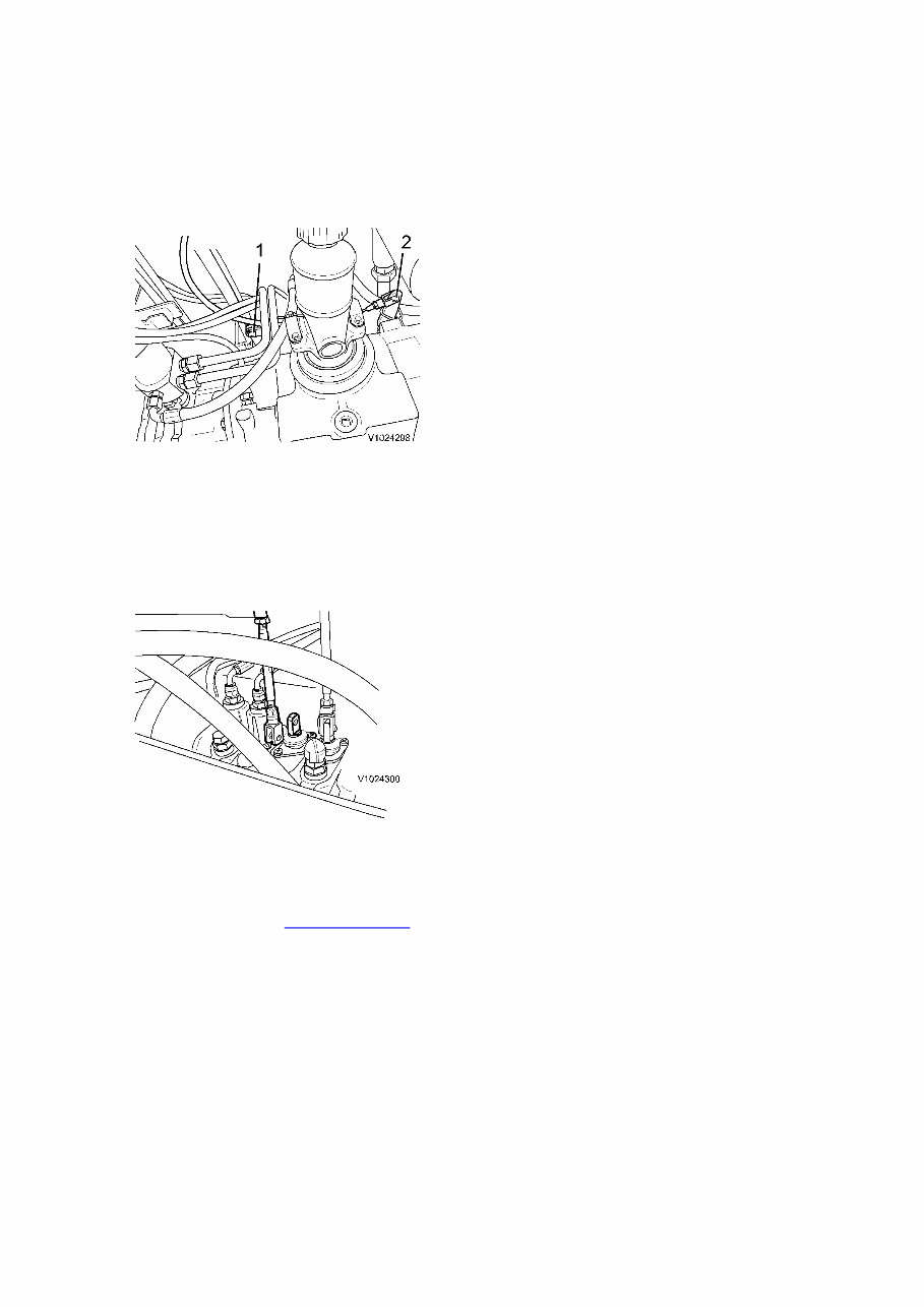
Figure 15 1. Plastic cover 21. If the machine is equipped with manually operated parking brake: Fit the parking brake cable to the rear axle. Figure 16 Rear axle 1. 2. Pin and washer Clevis pin 22. If the machine is equipped with extendible dipper: Fit the extendible dipper linkage to the main control valve. Figure 17 Main control valve 23. Install the rear wheels. Rear wheels weight, see . 771 Wheels, weights Tightening torque: 600 ±50 Nm (440 ±37 lbf ft)
Figure 18 24. Remove the stands. 25. Install the stabilizer lever handles and the screws to the casing. Figure 19 Backhoe controls 1. 2. 3. 4. Casing Screws Stabilizer levers Bellows 26. Remove the M16 lifting eyes and fit the screws. 27. Connect the battery disconnect switch. 28. Start the machine and check that there are no leakages.
The Volvo BL70 Backhoe Loader Service Repair Manual is a comprehensive guide containing detailed information, diagrams, real photo illustrations, and schemes. It provides step-by-step operations for repair, servicing, technical maintenance, and troubleshooting procedures for your machine. This manual is essential for both professional mechanics and DIY enthusiasts. The manual is available in PDF format, offering the complete information needed for machine repair and maintenance.
With a total of 1304 pages and a file size of 122Mb, this English-language manual covers a wide range of topics, including general information, service and maintenance, engine, electrical and information systems, power transmission, brakes, steering, frame and wheels, cab and interior, and hydraulic system. Additionally, it includes hydraulic and electric schematics for comprehensive understanding.
One of the advantages of having the manual in PDF format is the ability to utilize the Search feature in Acrobat to quickly find specific information. This allows users to print out the exact pages they need, saving time and resources. The manual is suitable for all Volvo BL70 Backhoe Loader machines, with serial numbers covering all models.
If you have any questions or require further assistance, feel free to reach out. We may have the manual you've been searching for. Have a great day!