Kubota L35 Backhoe Loader Tractor Repair Service Manual
What's Included?
Lifetime Access
Fast Download Speeds
Online & Offline Access
Access PDF Contents & Bookmarks
Full Search Facility
Print one or all pages of your manual
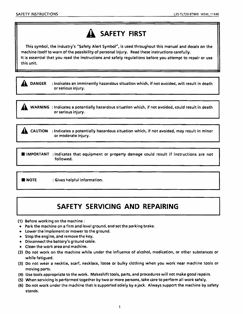
SAFETY INSTRUCTIONS L3S·TL720·BT900 WSM,11640 A SAFETY FIRST This symbol, the industry's "Safety Alert Symbol", is used throughout this manual and decals on the machine itself to warn of the possibility of personal injury. Read these instructions carefully. It is essential that you read the instructions and safety regulations before you attempt to repair or use this unit. A DANGER : Indicates an imminently hazardous situation which, if not avoided, will result in death or serious injury. A WARNING : Indicates a potentially hazardous situation which, if not avoided. could result in death or serious injury. A CAUTION : Indicates a potentially hazardous situation which, if not avoided, may result in minor or moderate injury. • IMPORTANT : Indicates that equipment or property damage could result if instructions are not followed. • NOTE : Gives helpful information . SAFETY SERVICING AND REPAIRING (1) Before working on the machine: • Park the machine on a firm and level ground, and set the parking brake. • Lower the implement or mower to the ground. • Stop the engine, and remove the key. • Disconnect the battery's ground cable. • Clean the work area and machine. (2) Do not work on the machine while under the influence of alcohol, medication, or other substances or while fatigued. (3) Do not wear a necktie, scarf, necklace, loose or bulky clothing when you work near machine tools or moving parts. (4) Use tools appropriate to the work. Makeshift tools, parts, and procedures will not make good repai rs. (5) When servicing is performed together by two or more persons, take care to perform all work safely. (6) Do not work under the machine that is supported solely by a jack. Always support the machine by safety stands.
L35·TL720·BT900 WSM,11640 SAFETY INSTRUCTIONS (7) If the engine must be running to do same work, make sure the area is well ventilated. Never run the engine in a closed area. The exhaust gas contains poisonous carbon monoxide. (8) Do not touch the rotating or hot parts while the engine is running. (9) Fuel is extremely flammable and explosive under certain conditions. Do not smoke or allow flames or sparks in your working area. (10) To avoid sparks from an accidental short circuit, always disconnect the battery's ground cable first and connect it last. (11) Sulfuric acid in battery electrolyte is poisonous. It is strong enough to burn skin, clothing and cause blindness if splashed into eyes. Keep electrolyte away from eyes, hands and clothing. If you spill electrolyte on yourself, flush with water. and get medical attention immediately. (12) Battery gas can explode. Keep sparks and open flame away from the top of battery, especially when charging the battery. (13) Never remove the radiator cap while the engine is running. or immediately after stopping. Otherwise. hot water will spout out from radiator. Wait for more than ten minutes to cool the radiator. before removing the cap. (14) Escaping fluid (fuel or hydraulic oil) under pressure can penetrate the skin causing serious injury. Relieve pressure before disconnecting hydraulic or fuel lines. Tighten all connections before applying pressure. (15) Do not start the engine by shorting across starter terminals. (16) Unauthorized modifications to the machine may impair the function and I or safety and affect machine life. (17) Do not alter or remove any part of machine safety system. (18) Keep a first aid kit and fire extinguisher handy at all times. (19) Be sure to chock the wheels to prevent accident during servicing the machine. 2
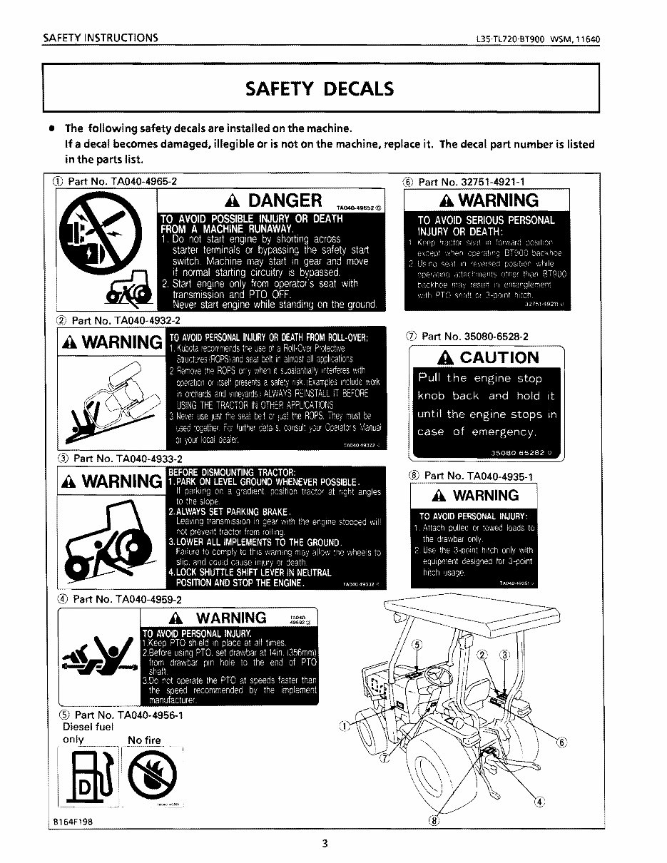
SAFETY , INSTRUCTIONS L35·TL720·BT900 WSM, 11640 SAFETY DECALS • The following safety decals are installed on the machine. If a decal becomes damaged, illegible or is not on the machine, replace it. The decal part number is listed in the parts list. A DANGER TA040-49652@ _~_Iii o Part No. TA040-4959-2 ® Part No. T A040-4956-1 Diesel fuel B164F198 Part No. 32751-4921-1 3
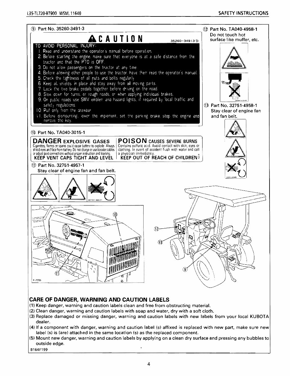
L3HL720·BT900 WSM,11640 SAFETY INSTRUCTIONS ~®~P_a_rt_N_o_._3_52_6_0_~_4_9_1-_3~~~~~~~~~~~~~~~~~~@PartNo.~04~~5~1 Do not touch hot ACAUTION 35260-34913@ surface like muffer, etc. TO AVOID PERSONAL INJURY: I. Read and understand the operators manual before operation. 2. Before starting the engine. make sure that everyone IS at a safe distance from the tractor and that the PTO is OFF. 3. Do not allow passengers on the tractor at any time 4. Before ailowing other people to use the tractor. have them read the operator'5 manual. 5. Check the tightness of all ruts and bolts regularly. 6. Keep ali shields in place and stay away from all moving parts. 7 Lock the two brake pedals together before driving on the road. B 51011. down for turns, or rough roads, or when applying individual brakes, 9. On public roads use SMV emblem ana hazard lights, if required by local traHic and safety regulations 10 Pull only from the drawbar I I. Berore dismounting, lower the Ifnpiement. set the parking brake, stop the engine and remove the key. ® Part No. TA040-3015-1 ~---, i 1--\ • n)\\\\I1\\\\\l~ I @ Part No. 32751-4958-1 Stay clear of engine fan and fan belt. DANGER EXPLOSIVE GASES Cigarettes. flames or sparks could cause battery to explode. Always shield eyes and face from battery. Do not charge or use booster cables or adjust post connections Without prQper jr,struction and training. KEEP VENT CAPS TIGHT AND LEVEL POI SON CAUSES SEVERE BURNS Contains sulfu,ic acid. Avoid contact with skin, eyes or clothing, In event of accident flush with water and call a physician immediately. • KEEP OUT OF REACH OF CHILDREN 6 @ Part No. 32751-4957-1 Stay clear of engine fan and fan belt. CARE OF DANGER, WARNING AND CAUTION LABELS (1) Keep danger, warning and caution labels clean and free from obstructing material. (2) Clean danger, warning and caution labels with soap and water, dry with a soft cloth. (3) Replace damaged or missing danger, warning and caution labels with new labels from your local KUBOTA dealer. (4) If a component with danger, warning and caution label (s) affixed is replaced with new part, make sure new label (s) is (are) attached in the same location (s) as the replaced component. (5) Mount new danger, warning and caution labels by applying on a clean dry surface and pressing any bubbles to outside edge. B164F199 4
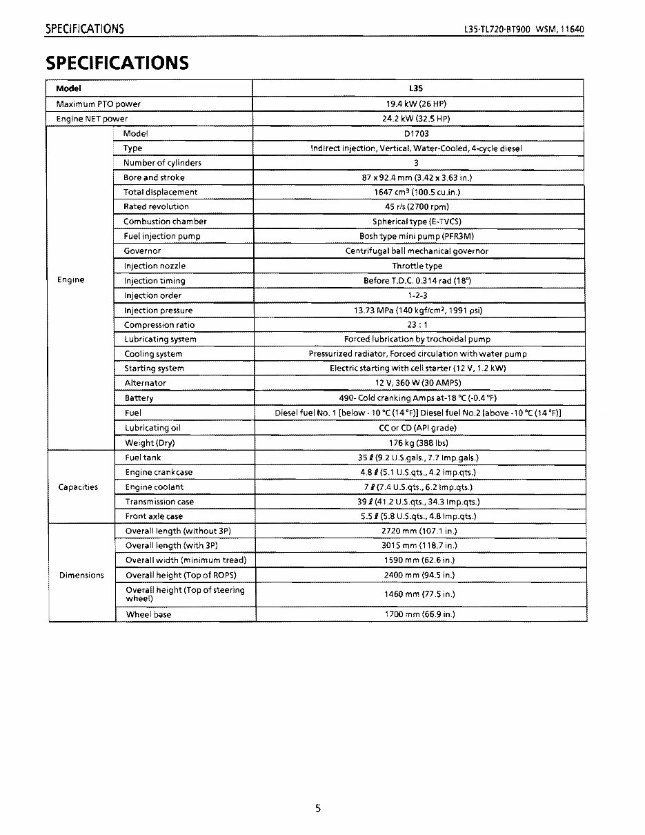
SPECIFICATIONS L3HL720'BT900 WSM, 11640 SPECIFICATIONS Model L35 Maximum PTO power 19.4kW(26HP) Engine NET power 24.2 kW (32.5 HP) Engine Model 01703 Type Indirect injection, Vertical, Water-Cooled, 4-cycle diesel I Number of cylinders 3 Bore and stroke 87 x92.4 mm (3.42 x 3.63 in.) Total displacement 1647 cm 3 (100.5 cu.in.) Rated revolution 45 rls (2700 rpm) Combustion chamber Spherical type (E-TVCS) Fuel injection pump Bosh type mini pump (PFR3M) Governor Centrifugal ball mechanical governor Injection nozzle Throttle type Injection timing Before T.D.C. 0.314 rad (18") Injection order 1-2-3 Injection pressure 13.73 MPa (140 kgf/cm 2 , 1991 psi) Compression ratio 23: 1 lubricating system Forced lubrication bytrochoidal pump Cooling system Pressurized radiator, Forced circulation with water pum p Starting system Electric starting with cell starter (12 V, 1.2 kW) Alternator 12 V, 360 W (30 AMPS) Battery 490- Cold cranking Amps at-18°C (-0.4 OF) Fuel Diesel fuel No.1 [below -10°C (14 OF)] Diesel fuel NO.2 [above·1 0 °c (14 OF)] lubricating oil CC or CD (API grade) Weight (Dry) 176 kg (388Ibs) Capacities Fuel tank 351 (9.2 U.S.gals., 7.7Imp.gals.) Engine crankcase 4.81 (5.1 U.S.qts., 4.2 Imp.qts.) Engine coolant 71(7.4 U.S.qts., 6.2Imp.qts.) Transmission case 391 (41.2 U.S.qts., 34.3lmp.qts.) Front axle case 5.51 (5.8 U.S.qts., 4.8Imp.qts.) Dimensions Overall length (without 3P) 2720 mm (107.1 in.) Overall length (with 3P) 3015 mm (118.7 in.) Overall width (minimum tread) 1590 m m (62.6 in.) Overall height (Top of ROPS) 2400 mm (94.5 in.) Overall height (Top of steering wheel) 1460 mm (77.5 in.) Wheel base 1700 mm (66.9 in.) 5
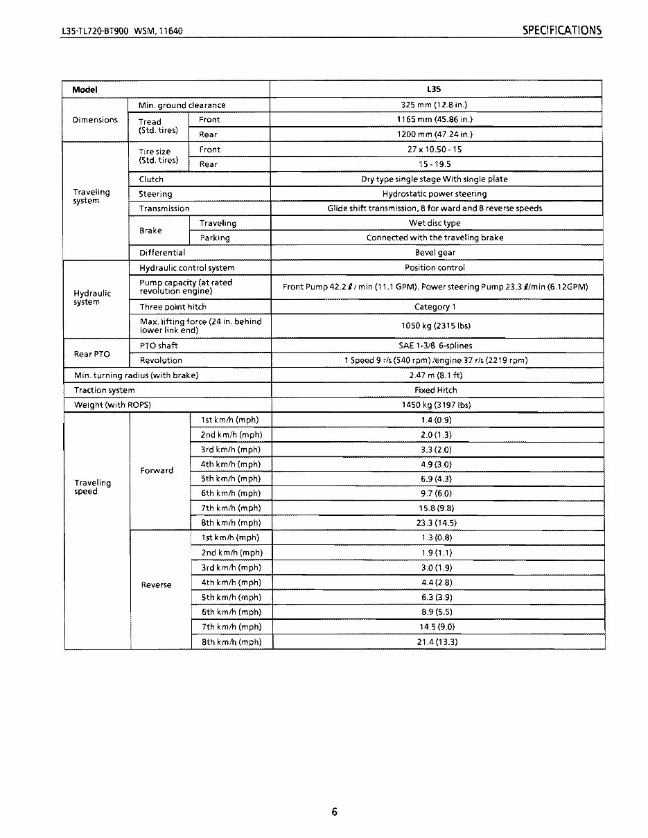
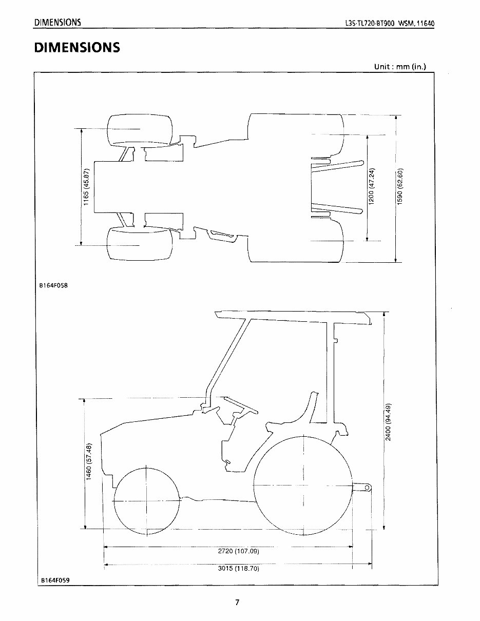
L3HL720'BT900 WSM,11640 SPECIFICATIONS Model Min. ground clearance Dimensions Front (Std. tires) Tread Rear Tire size Front (Std. tires) Rear Clutch Traveling Steering system Transmission Traveling Brake Parking Differential Hydraulic control system Hydraulic system Three point hitch Max. lifting force (24 in. behind lower link end) PTOshaft RearPTO Revolution Min. turning radius (with brake) Traction system Weight (with ROPS) lstkm/h(mph) 2nd km/h (mph) 3rd km/h (mph) 4th km/h (mph) Forward 5th km/h (mph) Traveling speed 6th km/h (mph) 7th km/h (mph) 8th km/h (mph) 1st km/h (mph) 2nd km/h (mph) 3rd km/h (mph) 4th km/h (mph) Reverse 5th km/h (mph) 6th km/h (mph) 7th km/h (mph) 8th km/h (mph) pumPt capacity (at rated Front Pump 42.211 min (11.1 GPM). Power steering Pump 23.311min (6.12GPM) revo ution engine) L35 325 mm (12.S in.) 1165 mm (45.S6 in.) 1200 mm (47.24 in.) 27x 10.50-15 15-19.5 Dry type single stage With single plate Hydrostatic power steering Glide shift transmission, S for ward and S reverse speeds Wet disc type Connected with the traveling brake Bevel gear Position control Category 1 1050 kg (2315Ibs) SAE 1-3/S 6-splines 1 Speed 9 rls(540 rpm)/engine 37 rls(2219 rpm} 2.47 m (S.l ft) Fixed Hitch 1450 kg (3197Ibs) 1.4(0.9) 2.0 (1.3) 3.3 (2.0) 4.9 (3.0) 6.9 (4.3) 9.7 (6.0) 15.S (9.S) 23.3 (14.5) 1.3 (O.S) 1.9 (1.1) 3.0 (1.9) 4.4 (2.S) 6.3 (3.9) 8.9 (5.5) 14.5 (9.0) 21.4 (B.3) 6
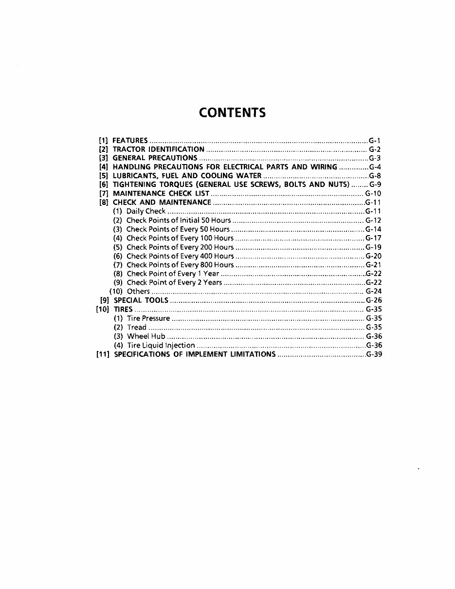
CONTENTS [1] FEATURES ....................................................................................................... G-1 [2] TRACTOR IDENTIFICATION ............................................................................ G-2 [3] GENERAL PRECAUTIONS ................................................................................ G-3 [4] HANDLING PRECAUTIONS FOR ELECTRICAL PARTS AND WIRING .............. G·4 [5] LUBRICANTS, FUEL AND COOLING WATER ..................................................G-8 [6] TIGHTENING TORQUES (GENERAL USE SCREWS, BOLTS AND NUTS) ........ G-9 [7] MAINTENANCE CHECK LIST ........................................................................ G-10 [8] CHECK AND MAINTENANCE ........................................................................ G-11 (1) Daily Check ............................................................................................. G·11 (2) Check Poi nts of Initial 50 Hours .............................................................. G·12 (3) Check Points of Every 50 Hours ............................................................... G-14 (4) Check Points of Every 100 Hours ............................................................. G-17 (5) Check Poi nts of Every 200 Hou rs ............................................................. G-19 (6) Check Points of Every 400 Hours ............................................................. G·20 (7) Check Poi nts of Every 800 Hours ............................................................. G·21 (8) Check Point of Every 1 Year ..................................................................... G·22 (9) Check Point of Every 2 Years ................................................................... G·22 (10) Others .................................................................................................... G-24 [9] SPECIAL TOOLS ............................................................................................ G-26 [10] TIRES ............................................................................................................ G·35 (1) Tire Pressure ........................................................................................... G-35 (2) Tread ...................................................................................................... G·35 (3) Wheel Hub ............................................................................................. G-36 (4) Tire Liquid Injection ................................................................................G-36 [11] SPECIFICATIONS OF IMPLEMENT UMITATIONS ..........................................G·39
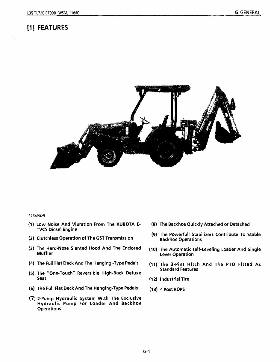
l3Hl720'BT900 WSM, 11640 G GENERAL [1] FEATURES B164P029 (1) Low Noise And Vibration From The KUBOTA E- TVCS Diesel Engine (2) Clutchless Operation of The GST Transmission (3) The Hard-Nose Slanted Hood And The Enclosed Muffler (4) The Full Flat Deck And The Hanging -Type Pedals (5) The "One·Touch" Reversible High-Back Deluxe Seat (6) The Full Flat Deck And The Hanging-Type Pedals (7) 2-Pump Hydraulic System With The Exclusive Hydraulic Pump For Loader And Backhoe Operations (8) The Backhoe Quickly Attached or Detached (9) The Powerfull Stabilizers Contribute To Stable Backhoe Operations (10) The Automatic self-Leveling Loader And Single Lever Operation (11) The 3-Pint Hitch And The PTO Fitted As Standard Features (12) Industrial Tire (13) 4 Post ROPS G-1
This workshop service manual for the Kubota L35 Backhoe Loader Tractor is designed for mechanical technicians familiar with service procedures for BRP products. It covers repair and overhaul of the Kubota L35 Backhoe Loader Tractor, including instructions on components manufactured for this model. The manual provides reliable information and emphasizes particular information denoted by the wording and symbols: WARNING, CAUTION, NOTE.
It includes procedures for routine maintenance, servicing, diagnostic, and repair procedures. Whether for professional mechanics or DIY enthusiasts, this manual enables individuals to perform maintenance and repairs, potentially saving time and money. Safety equipment and precautions are emphasized, along with the use of recommended or required special tools for adjustments or repairs.
The manual aims to help users get the best value from their Kubota L35 Backhoe Loader Tractor and contains all necessary instructions for any repair it may require. It is available in English and is delivered electronically via email. The content depicts parts and/or procedures applicable to the particular product at the time of writing.
Specifications:
Tune ups for Kubota L35 Backhoe Loader Tractor
Maintenance for Kubota L35 Backhoe Loader Tractor
Removal & install procedures for Kubota L35 Backhoe Loader Tractor
Assemblies & disassemblies for Kubota L35 Backhoe Loader Tractor
Fuel system for Kubota L35 Backhoe Loader Tractor
Ignition for Kubota L35 Backhoe Loader Tractor
Lubrication system for Kubota L35 Backhoe Loader Tractor
Exhaust for Kubota L35 Backhoe Loader Tractor
Electrical system for Kubota L35 Backhoe Loader Tractor
Body for Kubota L35 Backhoe Loader Tractor
More extensive repair involving ENGINE and TRANSMISSION disassembly for Kubota L35 Backhoe Loader Tractor
General Maintenance Tags:
Air cleaner element renewal
Air cleaner temperature control check
Auxiliary drivebelt check
Battery electrolyte level check
Battery terminal check
Brake hydraulic fluid renewal
Brake hydraulic system seal and hose renewal
Brake pipe and hose check
Choke adjustment check
And more...
This workshop service manual is a valuable resource for maintaining and repairing the Kubota L35 Backhoe Loader Tractor, providing essential information for both professional mechanics and DIY enthusiasts.
Recently Viewed
5,521,897Happy Clients
2,594,462eManuals
1,120,453Trusted Sellers
15Years in Business
Price:
Actual Price:
Kubota L35 Backhoe Loader Tractor Repair Service Manual