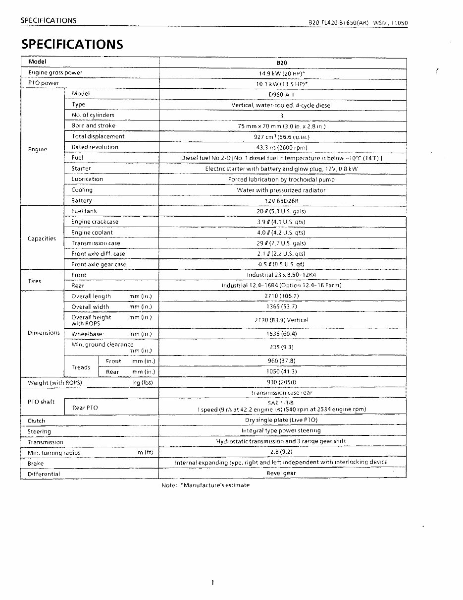
SPECIFICATIONS B20fL420BI650(AR) WSM,11050 SPECIFICATIONS ( Model B20 Engine gross power 14.9 kW (20 HP)* PTO power 101 kW(135HP)' Model D950AT Type Vertical, water-cooled, 4-cycle diesel No. of cylinders 3 Bore and stroke 75 mm x 70 mm (3.0 in. x 2,B In) Total displacement 927 cm 3 (56.6 cu.in.) Engine Rated revolution 43.3 rls (2600 rpm) Fuel Diesel fuel No,2-D INo. 1 diesel fuel If temperature IS below -10"( (14'1) I Starter Electric starter with battery and glow plug, 12V, 0.8 kW Lubrication Forced lubrication by trochOldal pump Cooling Water with pressurized radiator Battery 12V 65D26R Fuel tank 20 i (53 U.S, gals) Engine crackcase 3,9 i (4,1 U.s. qts) Engine coolant 4.0 i (42 U.S qts) Capacities Transm ission case 29 i (77 U.S gals) Front axle diff. case 2.1 U(2,2 U.S. qts) Front axle gear case 0.5 U(05 U.S. qt) Front Industrial 23 x 8.50-12R4 Tires IndustliaI12.4-16R4 (Option 12.4-16 Farm) Rear Overall length mm(in.) 2710 (1067) Overall Width mm(in.) 1365(537) Overall height mm(in) 2130 (839) Vertical With ROPS Dimensions Wheelbase mm (In.) 1535 (60.4) Min. ground clearance mm(ill.) 235 (9 3) I Front mm (in) 960 (378) Treads I mm(in) 1050 (413) Rear Weight (with ROPS) kg (Ibs) 930 (2050) I ransmisslon case rear PTO shaft SAE 13/8 Rear PTO 1 speed (9 r/s at 42.2 engine ./s) (540 rpm at 2534 engine rpm) i Clutch Dry single plate (Live PTO) Steering Integral type power steeling Transmission Hydrostatic transmission and 3 range gear shift Min. turning radius m (ft) 2.8 (92) Brake Internal expanding type, right and left independent with mterlockmg deVice Differentia I Bevel gear Note: *Manufacture's estimate
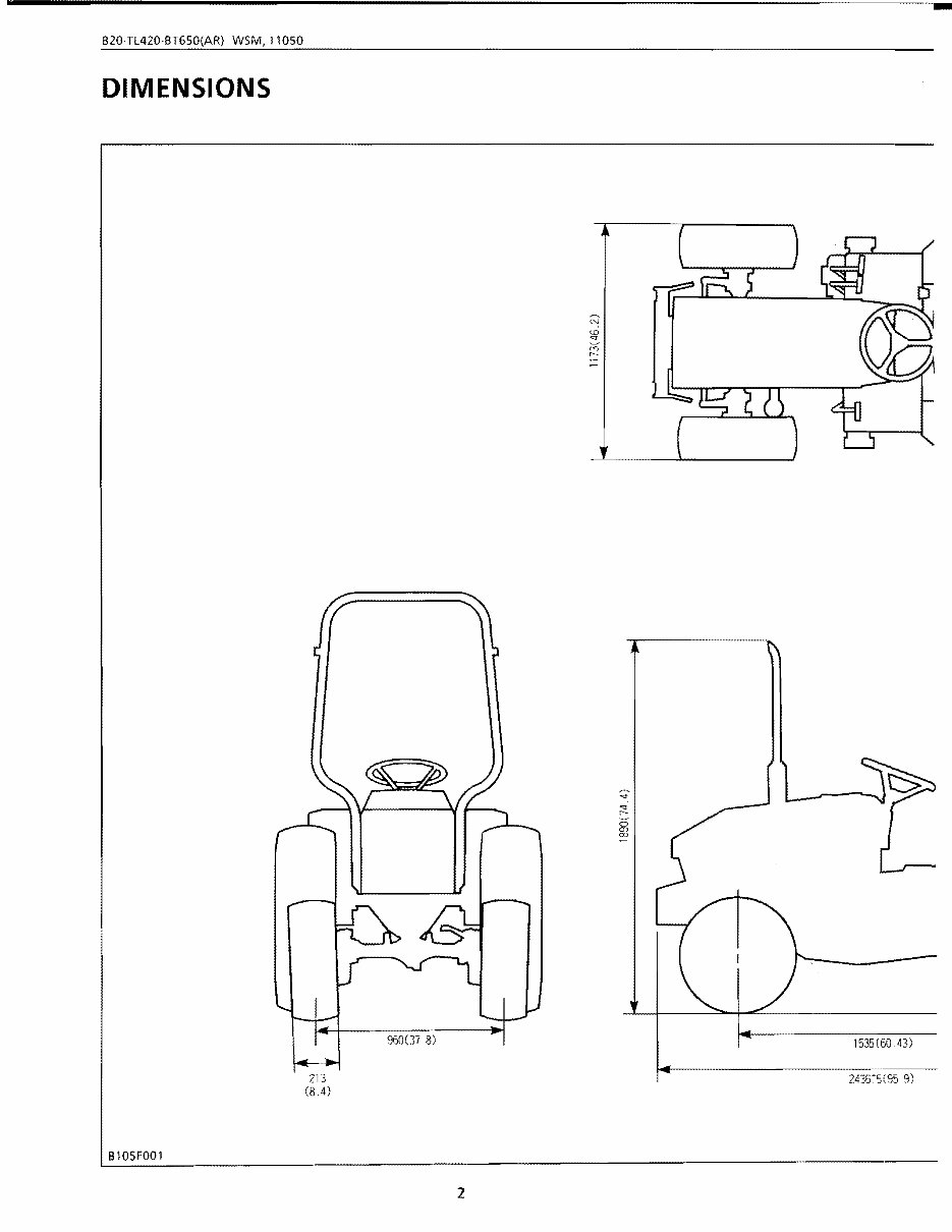
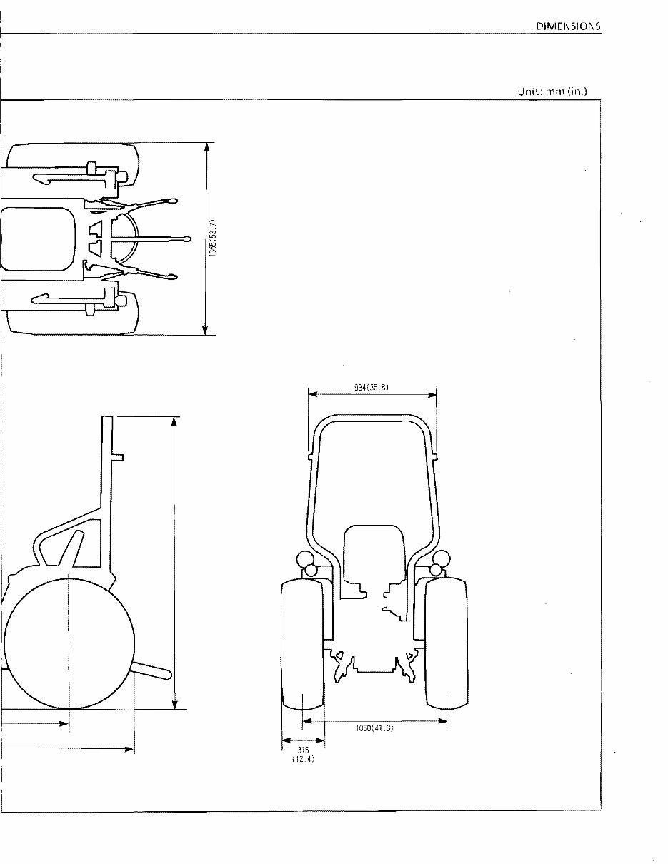
I DIIVI El'JSIONS Unll: mOl (ill.) ~ I I f 934(368) 315 1050(413) (12 4)
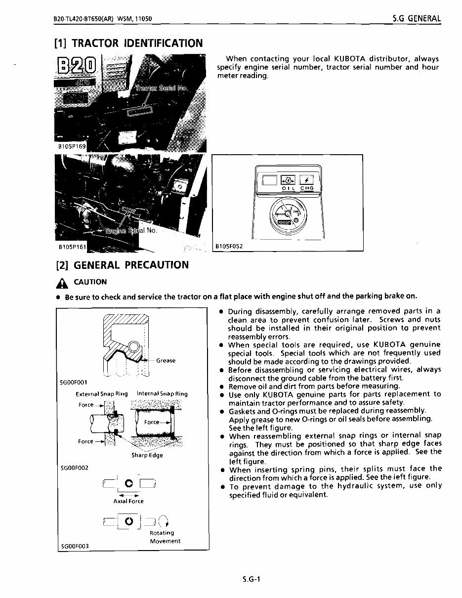
-- -- B20·Tl420·BT650(AR) WSM,11050 S.G GENERAL [1] TRACTOR IDENTIFICATION When contacting your local KUBOTA distributor, always specify engine serial number, tractor serial number and hour meter reading. [2] GENERAL PRECAUTION A CAUTION D~w OIL CHG Bl0SFOS2 • Be sure to check and service the tractor on a flat place with engine shut off and the parking brake on. ~""'>+-Grease SGOOFOOl External Snap Ring Internal Snap Ring FO"~ ~~ Fo<" . '~"h ~ , Fo." -'f; . ~~;¢~\j\,r· SGOOF002 SharPEdge - Axial Force c_t_o pO Rotating Movement • During disassembly, carefully arrange removed parts in a clean area to prevent confusion later. Screws and nuts should be installed in their original position to prevent reassembly errors. • When special tools are required, use KUBOTA genuine special tools. Special tools which are not frequently used should be made according to the drawings provided. • Before disassembling or servicing electrical wires, always disconnect the ground cable from the battery first. • Remove oil and dirt from parts before measuring. • Use only KUBOTA genuine parts for parts replacement to maintain tractor performance and to assure safety. • Gaskets and O-rings must be replaced during reassembly. Apply grease to new O-rings or oil seals before assembling . See the left figure. • When reassembling external snap rings or internal snap rings. They must be positioned so that sharp edge faces against the direction from which a force is applied. See the left figure. • When inserting spring pins, their splits must face the direction from which a force is applied. See the left figure. • To prevent damage to the hydraulic system, use only specified fluid or equivalent. SGOOF003 S.G-l
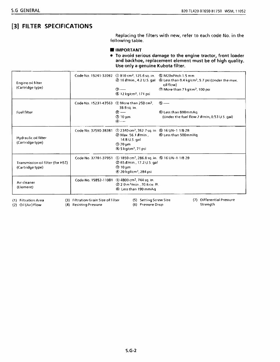
S.G GENERAL B20TL420·BT650·BT750 WSM,11052 [3] FilTER SPECIFICATIONS Replacing the filters with new, refer to each code No. in the following table . • IMPORTANT • To avoid serious damage to the engine tractor, front loader and backhoe, replacement element must be of high quality. Use only a genuine Kubota filter. Engine oil filter (Cartridge type) Code No. 15241-32092 C!)810em 2 , 125.6sq.in. @ M20xPiteh 1.5 mm ® 161/min., 4.2 U.s gal ® Less than 0.4 kg/em2, 5.7 psi (Under the max. oil flow) @ (j) More than 7 kglcm], 100 psi @) 12kg/em2,171 psi Fuel filter Code No. 15231-43563 Cj) More than 250 em 2 , @- 38.8 sq. in. ®- ® Less than 800mmAq @lOpm (Under the fuel flow 21/min. 0.53 U.s gal) @) Hydraulic oil filter (Cartridge type) Code No. 32590·38381 cD 23110 em', 362.7sq. in. @ 16 UN-lI/8-2B ® Max. 56.1 I/min , ® Less than 500mmHq 14.8 U.S. gal @7 0 1lm @.) 5 kg/em]. 71 psi Transmission 011 filter (for HST) (Cartridge type) Code No. 32701·37951 CD 1850 em?, 286.8 sq in. ® 16 UN-l-I/8-2B ®65l!min .• 17.2U.S.gal @ IOllm @) 20 kgf/em], 284 psi Air cleaner (Element) Code No. 15852-11081 Cj) 4800 em2, 744 sq in. (~20 m 3 /min, 70.6 cu. ft. ® Less than 190 mmAq (1) Filtration Area (3) Filtration Grain Sile of Filter (5) Setting Screw Size (7) Differential Pressure (2) Oil (Air) Flow (4) Resisting Pressure (6) Pressure Drop Strength S,G-2
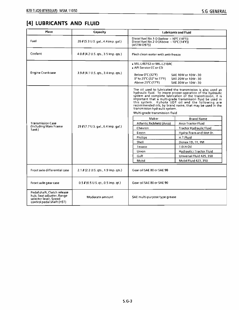
B20·TL420·BT650(AR) WSM,11050 S.G GENERAL [4] LUBRICANTS AND FLUID Place Capacity Lubricants and Fluid Diesel fuel No.l-D (below - 10°C (14°F)) Fuel 20 I (5.3 U.S. gal., 4.4lmp. gaL) Diesel fuel No.2-D (Above - 10°C (14°F)) (ASTM D975) Coolant 4.0 I (4.2 US qts., 3.5 Imp. qts.) Flesh clean water with anti-freeze • MIL-L46152 or MIL-L2104C • API Service CC or CD Engine Crankcase 3.9/(4.1 U.S. qts., 3.4 Imp. qts.) Below O°C (32°F) SAE 10Wor 10W-30 0° to 25°C (32° to 77°F) SAE 20Wor 10W-30 Above 25°C (77°F) SAE 30Wor lOW - 30 The oil used to lubricated the transmission is also used as hydraulic fluid. To insure proper operation of the hydraulic system and complete lubrication of the transmission, it is important that a multi-grade transmission fluid be used in this system. Kubota UDT oil and the following are recommended oils, by brand name, that may be used in the transmission hydraulic system. Multi-grade transmission fluid Maker Brand Name Transmission Case Atlantic Richfield (Arco) Arco Tractor Fluid (Including Main Frame 291 (7.7 U.S. gal., 6.4 Imp. gaL) Chevron Tractor Hvdraulic Fluid Tank) Exxon Hydra-Trans and Wet Br. Phillips H.T.Fluid Shell DonaxTD, n, TM Texaco T.D.HOil Union Hydraulic / Tractor Fluid Gulf Universal ~Iuid 425, 350 Mobil Mobil Fluid 423, 350 Front axle differential case 2.11 (2.2 U.S. qts., 1.9 Imp. qts.) Gear oil SAE 80 or SAE 90 Front axle gear case 0.51 (0.5 U.S. qt., 0.5 Imp. qt.) Gear oil SAE 80 or SAE 90 Pedal shaft, Clutch release hub, Seat adjuster, Range selector lever, Speed Moderate amount SAE multi-purpose type grease control pedal shaft (HST) S.G-3
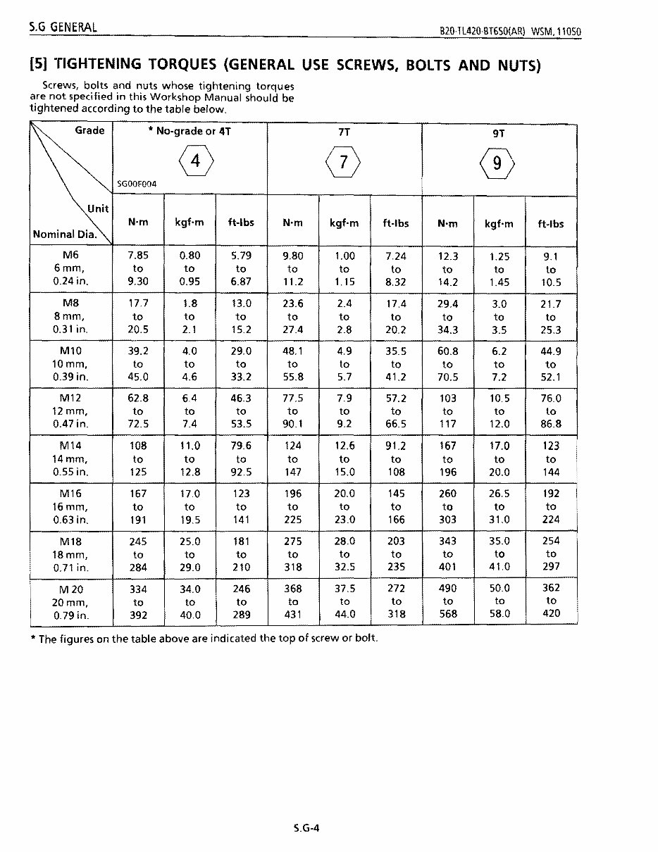
S.G GENERAL B20·Tl420·BT650(AR} WSM.11050 [5] TIGHTENING TORQUES (GENERAL USE SCREWS, BOLTS AND NUTS) Screws, bolts and nuts whose tightening torques are not specified in this Workshop Manual should be tightened according to the table below. Grade * No-grade or 4T 0 SGOOFOO4 Unit N'm kgf'm ft-Ibs N'm Nominal Dia. M6 7.85 0.80 5.79 9.80 6mm, to to to to 0.24in. 9.30 0.95 6.87 11.2 M8 17.7 1.8 13.0 23.6 8mm, to to to to 0.31 in. 20.5 2.1 15.2 27.4 Ml0 39.2 4.0 29.0 48.1 10mm, to to to to 0.39 in. 45.0 4.6 33.2 55.8 M12 62.8 6.4 46.3 77.5 12mm, to to to to 0.47 in. 72.5 7.4 53.5 90.1 M14 108 11.0 79.6 124 14mm, to to to to 0.55 in. 125 12.8 92.5 147 M16 167 17.0 123 196 16 mm, to to to to 0.63 in. 191 19.5 141 225 M18 245 25.0 181 275 18mm, to to to to 0.71 in. 284 29.0 210 318 M20 334 34.0 246 368 20mm, to to to to 0.79 in. 392 40.0 289 431 7T (}) kgf'm 1.00 to 1.15 2.4 to 2.8 4.9 to 5.7 7.9 to 9.2 12.6 to 15.0 20.0 to 23.0 28.0 to 32.5 37.5 to 44.0 9T CD ft-Ibs N'm kgf'm ft-Ibs 7.24 12.3 1.25 9.1 to to to to 8.32 14.2 1.45 10.5 17.4 29.4 3.0 21.7 to to to to 20.2 34.3 3.5 25.3 35.5 60.8 6.2 44.9 to to to to 41.2 70.5 7.2 52.1 57.2 103 10.5 76.0 to to to to 66.5 117 12.0 86.8 91.2 167 17.0 123 to to to to 108 196 20.0 144 145 260 26.5 192 to to to to 166 303 31.0 224 203 343 35.0 254 to to to to 235 401 41.0 297 272 490 50.0 362 to to to to 318 568 58.0 420 * The figures on the table above are indicated the top of screw or bolt. S.G-4
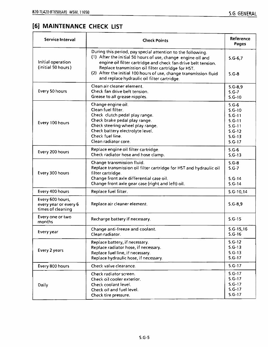
B20·Tl420·BT650(AR) W5M, 11050 S.G GENERAL [6] MAINTENANCE CHECK LIST Reference Service Interval Check Points Pages During this period, pay special attention to the following. (1) After the initial 50 hours of use, change engine oil and S.G-6,7 Initial operation engine oil filter cartridge and check fan drive belt tension. (initial 50 hours) Replace transmission oil filter cartridge for HST. (2) After the initial 100 hours of use, change transmission fluid S.G-8 and replace hydraulic oil filter cartridge. Clean air cleaner element. S.G-8,9 Every 50 hours Check fan drive belt tension. S.G-7 Grease to all grease nipples. S.G-lO Change engine oil. S.G-6 Clean fuel filter. S.G-l0 Check clutch pedal play range. S.G-ll Check brake pedal play range. S.G-l1 Every 100 hours Check steering wheel play range. S.G-l1 Check battery electrolyte level. S.G-12 Check fuel line. S.G-13 Clean radiator core. S.G-17 Replace engine oil filter cartridge. S.G-6 Every 200 hours Check radiator hose and hose clamp. S.G-13 Change transmission fluid. S.G-8 Replace transmission oil filter cartridge for HST and hydraulic oil S.G-7 Every 300 hours filter cartridge. Change front axle differential case oil. S.G-14 Change front axle gear case (right and left) oil. S.G-14 Every 400 hours Replace fuel filter. S.G-l0,14 Every 600 hours, every year or every 6 Replace air cleaner element. S.G-8,9 times of cleaning Everyone or two S.G-15 Recharge battery if necessary. months S.G-15,16 Change anti-freeze and coolant. Every year S.G-16 Clean radiator. S.G-12 Replace radiator hose, if necessary. Replace battery, if necessary. S.G-13 Every 2 years S.G-13 Replace hydraulic hose, if necessary. Replace fuel line, if necessary. S.G-17 S.G-17 Check valve clearance. Every 800 hours S.G-17 Check oil cooler exterior. Check radiator screen. S.G-17 Daily S.G-17 Check oil and fuel level. Check coolant level. S.G-17 Check tire pressure. S.G-17 S.G-S
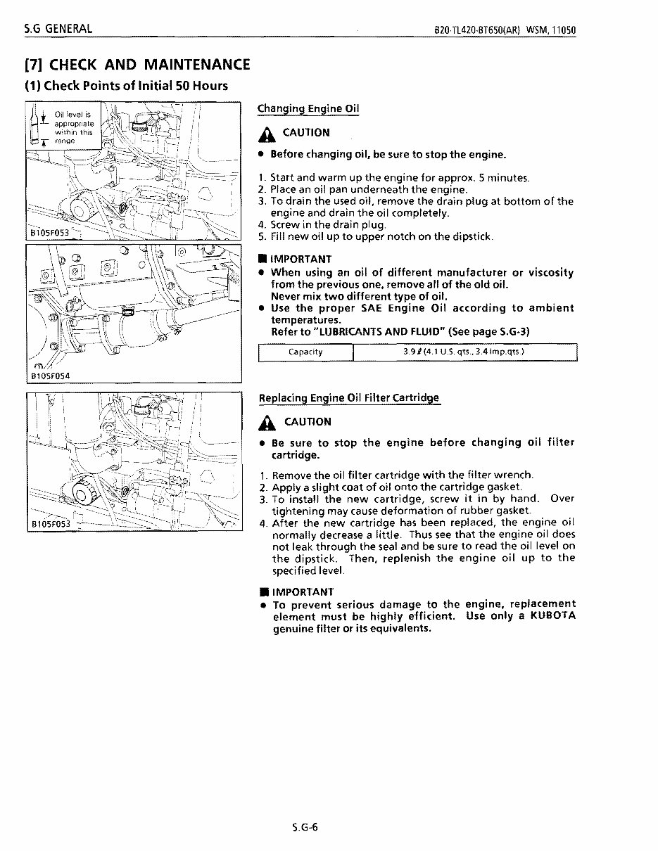
S.G GENERAL B20·TL420·BT650(AR) WSM.11050 [7] CHECK AND MAINTENANCE (1) Check Points of Initial 50 Hours i Oi.1 le.vel is ' . • ~ \ I'. appropriate within this .- range Changing Engine Oil A CAUTION • Before changing oil. be sure to stop the engine. 1. Start and warm up the engine for approx. 5 minutes. 2. Place an oil pan underneath the engine. 3. To drain the used oil, remove the drain plug at bottom of the engine and drain the oil completely. 4. Screw in the drain plug. 5. Fill new oil up to upper notch on the dipstick . • IMPORTANT • When using an oil of different manufacturer or viscosity from the previous one, remove all of the old oil. Never mix two different type of oil. • Use the proper SAE Engine Oil according to ambient temperatures. Refer to "LUBRICANTS AND FLUID" (See page S.G-3) Capacity 3.91 (4.1 U.S. qts .• 3.4Imp.qts.) Replacing Engine Oil Filter Cartridge A CAUTION • Be sure to stop the engine before changing oil filter cartridge. 1. Remove the oil filter cartridge with the filter wrench. 2. Apply a slight coat of oil onto the cartridge gasket. 3. To install the new cartridge, screw it in by hand. Over tightening may cause deformation of rubber gasket. 4. After the new cartridge has been replaced, the engine oil normally decrease a little. Thus see that the engine oil does not leak through the seal and be sure to read the oil level on the dipstick. Then, replenish the engi ne oil up to the specified level. • IMPORTANT • To prevent serious damage to the engine, replacement element must be highly efficient. Use only a KUBOTA genuine filter or its equivalents. S.G-6
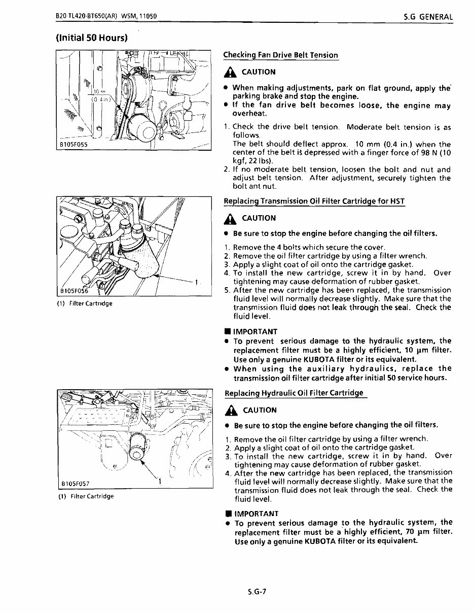
B20·TL420·BT650(AR) WSM,11050 S.G GENERAL (Initial 50 Hours) (1) Filter Cartridge B105F057 (1) Filter Cartridge Checking Fan Drive Belt Tension A CAUTION • When making adjustments, park on flat ground, apply the' parking brake and stop the engine. • If the fan drive belt becomes loose, the engine may overheat. 1. Check the drive belt tension. Moderate belt tension is as follows. The belt should deflect approx. 10 mm (0.4 in.) when the center of the belt i~ depressed with a finger force of 98 N (10 kgf. 22 Ibs). 2. If no moderate belt tension, loosen the bolt and nut and adjust belt tension. After adjustment. securely tighten the bolt ant nut. Replacing Transmission Oil Filter Cartridge for HST A CAUTION • Be sure to stop the engine before changing the oil filters. 1. Remove the 4 bolts which secure the cover. 2. Remove the oil filter cartridge by using a filter wrench. 3. Applya slight coat of oil onto the cartridge gasket. 4. To install the new cartridge, screw it in by hand. Over tightening may cause deformation of rubber gasket. 5. After the new cartridge has been replaced, the transmission fluid level will normally decrease slightly. Make sure that the transmission fluid does not leak through the seal. Check the fl uid level. • IMPORTANT • To prevent serious damage to the hydraulic system, the replacement filter must be a highly efficient. 10 11m filter. Use only a genuine KUBOTA filter or its equivalent. • When using the auxiliary hydraulics, replace the transmission oil filter cartridge after initial SO service hours. Replacing Hydraulic Oil Filter Cartridge A CAUTION • Be sure to stop the engine before changing the oil filters. 1. Remove the oil filter cartridge by using a filter wrench. 2. Apply a slight coat of oil onto the cartridge gasket. 3. To install the new cartridge, screw it in by hand. Over tightening may caUSe deformation of rubber gasket. 4. After the new cartridge has been replaced. the transmission fluid level will normally decrease slightly. Make sure that the transmission fluid does not leak through the seal. Check the fluid level. • IMPORTANT • To prevent serious damage to the hydraulic system, the replacement filter must be a' highly efficient, 70 11m filter. Use only a genuine KUBOTA filter or its equivalent. S.G-7
You're Reading a Preview
What's Included?
Lifetime Access
Fast Download Speeds
Online & Offline Access
Access PDF Contents & Bookmarks
Full Search Facility
Print one or all pages of your manual
$35.99
Kubota B20 Front End Loader Tractor Repair Service Manual
This workshop service manual for the Kubota B20 Front End Loader Tractor is designed for mechanical technicians familiar with service procedures for BRP products. It covers repair and overhaul of the Kubota B20 Front End Loader Tractor, assuming familiarity with general automobile practices. The manual includes instructions on components manufactured for the tractor and provides reliable information for routine maintenance, servicing, diagnostic, and repair procedures. It is useful for both professional mechanics and DIY enthusiasts.
For those intending to do maintenance and repair on their Kubota B20 Front End Loader Tractor, it is essential to use safety equipment and observe safety precautions. The manual also refers to special tools recommended or required to accomplish adjustments or repairs, often identified by their Kubota B20 Front End Loader Tractor special tool number and illustrated.
The manual aims to help users get the best value from their Kubota B20 Front End Loader Tractor and includes specifications and procedures available in an authorized Kubota B20 Front End Loader Tractor dealer service department. It emphasizes particular information denoted by the wording and symbols: WARNING, CAUTION, NOTE.
This is a complete service manual containing all necessary instructions needed for any repair the Kubota B20 Front End Loader Tractor may require. It is available in electronic format for fast and free delivery via email. The content depicts parts and/or procedures applicable to the particular product at the time of writing.
The manual covers a wide range of topics including tune-ups, maintenance, removal & install procedures, assemblies & disassemblies, fuel system, ignition, lubrication system, exhaust, electrical system, and more extensive repairs involving engine and transmission disassembly. It also includes general maintenance tags for various checks and renewals related to the tractor.
Reviews
Q&A
Recently Viewed
5,521,897Happy Clients
2,594,462eManuals
1,120,453Trusted Sellers
15Years in Business
Price:
Actual Price:
Kubota B20 Front End Loader Tractor Repair Service Manual


 Lifetime Access




