

JCB 214 214S Backhoe Loader Workshop Service Manual
What's Included?
Fast Download Speeds
Online & Offline Access
Access PDF Contents & Bookmarks
Full Search Facility
Print one or all pages of your manual

General Information
1
Care & Safety
2
Routine Maintenance
3
Attachments
A
Body & Framework
B
Electrics
C
Controls
D
Hydraulics
E
Transmission
F
Brakes
G
Steering
H
Engine
K
Service
Manual
3CX, 4CX, 214e, 214, 215,
217 & VARIANTS
Backhoe
Loader
From M/c No. 930000 Onwards
From M/c No. 903000 Onwards (USA)
PUBLISHED BY THE
TECHNICAL PUBLICATIONS DEPARTMENT
OF JCB SERVICE; © WORLD PARTS CENTRE,
WATERLOO PARK, UTTOXETER, ST14 5PA
ENGLAND
Tel. ROCESTER (01889) 590312
PRINTED IN ENGLAND
Publication No. 9803/3280 Issue 4

Introduction
This publication is designed for the benefit of JCB Distributor Service Engineers who are receiving, or have received, training
by JCB Technical Training Department.
These personnel should have a sound knowledge of workshop practice, safety procedures, and general techniques
associated with the maintenance and repair of hydraulic earthmoving equipment.
Renewal of oil seals, gaskets, etc., and any component showing obvious signs of wear or damage is expected as a matter of
course. It is expected that components will be cleaned and lubricated where appropriate, and that any opened hose or pipe
connections will be blanked to prevent excessive loss of hydraulic fluid and ingress of dirt. Finally, please remember above all
else SAFETY MUST COME FIRST!
The manual is compiled in sections, the first three are numbered and contain information as follows:
1 = General Information - includes torque settings and service tools.
2 = Care & Safety - includes warnings and cautions pertinent to aspects of workshop procedures etc.
3 = Routine Maintenance - includes service schedules and recommended lubricants for all the
machine.
The remaining sections are alphabetically coded and deal with Dismantling, Overhaul etc. of specific components, for
example:
A = Attachments
B = Body & Framework ...etc.
The page numbering in each alphabetically coded section is not continuous. This allows for the insertion of new items in later
issues of the manual.
Section contents, technical data, circuit descriptions, operation descriptions etc are inserted at the beginning of each
alphabetically coded section.
All sections are listed on the front cover; tabbed divider cards align directly with individual sections on the front cover for rapid
reference.
Where a torque setting is given as a single figure it may be varied by plus or minus 3%. Torque figures indicated are for dry
threads, hence for lubricated threads may be reduced by one third.
With the exception of slewing operations 'Left Hand' and 'Right Hand' are as viewed from the rear of the machine facing
forwards.
Machine Nomenclature
In this Service Manual, reference is made to machine models, e.g. 3CX, 4CX, these are European machine model names.
North American machine models have different names, the table below shows the European and the equivalent North
American nomenclature.
European North American
3CX = 214
4CX = 214S, 215S, 217S
9803/3280 Issue 1

Colour Coding
The following colour coding, used on illustrations to denote various conditions of oil pressure and flow, is standardised
throughout JCB Service publications.
9803/3280 Issue 1
A390940
Full Pressure
Pressure generated from operation of a service. Depending on application this may
be anything between neutral circuit pressure and M.R.V. operating pressure.
Pressure
Pressure that is above neutral circuit pressure but lower than that denoted by red.
Servo
Oil pressure used in controlling a device (servo).
Neutral
Neutral circuit pressure.
Exhaust
Cavitation
Oil subjected to a partial vacuum due to a drop in pressure (cavitation).
Lock Up
Oil trapped within a chamber or line, preventing movement of components (lock up).
Red
Pink
Orange
Blue
Green
Light
Green
Yellow

i
Section 1 General Information
9803/3280
Section 1
i
Issue 2*
Contents Page No.
Machine Identification Plate 1 - 1
Typical Vehicle Identification Number (VIN) 1 - 1
Typical Engine Identification Number 1 - 1
Serial Plates 1 - 2
Torque Settings 2 - 1
Service Tools Numerical List 3 - 1
Service Tools
- Body & Framework 4 - 1
- Electrics 4 - 4
- Hydraulics 4 - 6
- Transmission 4 - 10
- Engine 4 - 19*
Sealing and Retaining Compounds 5 - 1
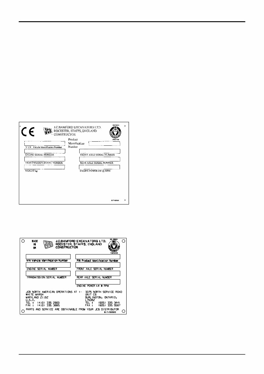
Machine Identification Plate
Your machine has an identification plate mounted on the
loader tower. The serial numbers of the machine and its
major units are stamped on the plate.
The serial number of each major unit is also stamped on the
unit itself. If a major unit is replaced by a new one, the serial
number on the identification plate will be wrong. Either
stamp the new number of the unit on the identification plate,
or simply stamp out the old number. This will prevent the
wrong unit number being quoted when replacement parts
are ordered.
The machine and engine serial numbers can help identify
exactly the type of equipment you have.
1 - 1
Typical Vehicle
Identification Number (VIN)
SLP 3CX T S V E 930000
A B C D E F G
A
World Manufacturer Identification
B
Machine Model
C
Steer Type (T= 2WS, F=4WS)
D
Build Type (S=Sideshift, C=Centremount, L=Loader)
E
Year of Manufacture:
2 = 2002
3 = 2003
4 = 2004
5 = 2005
6 = 2006
7 = 2007
8 = 2008
F
Manufacturer Location (E = England)
G
Product Identification Number (PIN)
Typical Engine
Identification Number
AB 50262 U 500405 P
A B C D E
A Engine Type
AB = 4 cylinder turbo
B Build Number
C Country of Origin
D Engine Sequence Number
E Year of Manufacture
Section 1 General Information
9803/3280
Section 1
1 - 1
Issue 1
S218131
U.K. and R.O.W.
North America
A246740
1 - 2
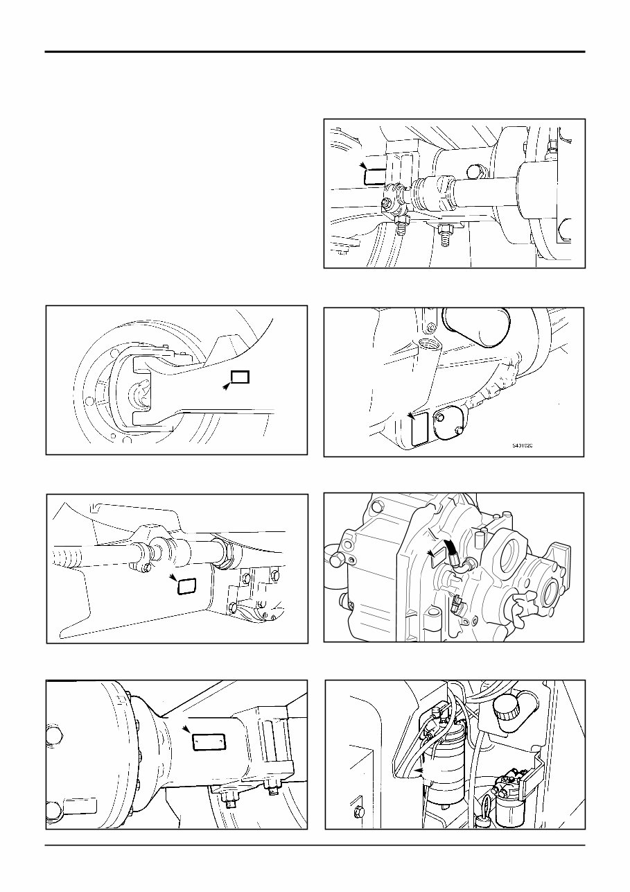
Serial Plates
A Front Axle (2WS machine)
B Front Axle (4WS machine)
C Rear Axle (2WS machine)
D Rear Axle (4WS machine)
E Synchro Shuttle Transmission
F Powershift Transmission
G Engine
Section 1 General Information
9803/3280
Section 1
1 - 2
Issue 1
E
F
G
A
S257580
A401030
S260120
B
C
S259100
S156571
S259110
D

2 - 1
Torque Settings
Use only where no torque setting is specified in the text. Values are for dry threads and may be within three per cent of the
figures stated. For lubricated threads the values should be REDUCED by one third.
UNF Grade 'S' Bolts
Bolt Size Hexagon (A/F) Torque Settings
in (mm) in Nm kgf m lbf ft
1/4 (6.3) 7/16 14 1.4 10
5/16 (7.9) 1/2 28 2.8 20
3/8 (9.5) 9/16 49 5.0 36
7/16 (11.1) 5/8 78 8.0 58
1/2 (12.7) 3/4 117 12.0 87
9/16 (14.3) 13/16 170 17.3 125
5/8 (15.9) 15/16 238 24.3 175
3/4 (19.0) 11/8 407 41.5 300
7/8 (22.2) 15/16 650 66.3 480
1 (25.4) 11/2 970 99.0 715
11/4 (31.7) 17/8 1940 198.0 1430
11/2 (38.1) 21/4 3390 345.0 2500
Metric Grade 8.8 Bolts
Bolt Size Hexagon (A/F) Torque Settings
(mm) mm Nm kgf m lbf ft
M5 (5) 8 7 0.7 5
M6 (6) 10 12 1.2 9
M8 (8) 13 28 3.0 21
M10 (10) 17 56 5.7 42
M12 (12) 19 98 10 72
M16 (16) 24 244 25 180
M20 (20) 30 476 48 352
M24 (24) 36 822 84 607
M30 (30) 46 1633 166 1205
M36 (36) 55 2854 291 2105
Rivet Nut Bolts/Screws
Bolt Size Torque Settings (for steel rivet nuts)
(mm) Nm kgf m lbf ft
M3 (3) 1.2 0.12 0.9
M4 (4) 3.0 0.3 2.0
M5 (5) 6.0 0.6 4.5
M6 (6) 10.0 1.0 7.5
M8 (8) 24.0 2.5 18.0
M10 (10) 48.0 4.9 35.5
M12 (12) 82.0 8.4 60.5
Note: All bolts used on JCB machines are high tensile and must not be replaced by bolts of a lesser tensile specification.
Section 1 General Information
9803/3280
Section 1
2 - 1
Issue 1

3 - 1
460/15708 Flow Test Adapter 4 - 13
460/15707 Banjo Bolt 4 - 13
1406/0011 Bonded Washer 4 - 7
1406/0014 Bonded Washer 4 - 7
1406/0018 Bonded Washer 4 - 7, 13
1406/0021 Bonded Washer 4 - 6, 4 - 7
1406/0029 Bonded Washer 4 - 7
1604/0003 Male Adapter 4 - 7
1604/0004 Male Adapter 4 - 7, 13
1604/0006 Male Adapter 4 - 6, 4 - 7
1604/0008 Adapter 4 - 6
1606/0003 Male Adapter 4 - 7
1606/0004 Male Adapter 4 - 7
1606/0007 Male Adapter 4 - 7
1606/0008 Male Adapter 4 - 7
1606/0009 Male Adapter 4 - 7
1606/0012 Male Adapter 4 - 6, 4 - 7
1606/0014 Male Adapter 4 - 7
1606/0015 Male Adapter 4 - 6, 4 - 7
1606/0017 Male Adapter 4 - 7
1612/0006 Adapter 4 - 6
2401/0222 O-ring 4 - 13
2403/0110 O-ring 4 - 13
2403/0108 O-ring 4 - 13
4101/0651 Retainer (High Strength) 5 - 1
4101/0250 Threadlocker and Sealer (10 ml) 5 - 1
4101/0251 Threadlocker and Sealer (50 ml) 5 - 1
4101/0451 Threadlocker 5 - 1
4102/0502 High Strength Gasketing 5 - 1
4102/0551 High Strength Threadlocker 5 - 1
4102/0933 Clear Silicone Sealant 5 - 1
4102/1212 Multi-Gasket 5 - 1
4102/1951 Threadseal 5 - 1
4102/2309 Black Polyurethane Sealant 5 - 1
4103/2109 Ultra Fast Adhesive (310ml) 5 - 1
4104/0251 Activator (Aersol) 5 - 1
4104/0253 Activator (Bottle) 5 - 1
4104/1203 Active Wipe 205 (250g) 5 - 1
4104/1206 Active Wipe 205 (30 ml) 5 - 1
4104/1310 Hand Cleaner 4 - 1
4104/1538 JCB Cleaner & Degreaser 5 - 1
4104/1557 Cleaner/Degreaser (400 ml) 5 - 1
4201/4906 Black Primer 206J (30ml) 5 - 1
816/00017 Adapter 4 - 8
816/00189 Blanking Cap 4 - 8
816/00190 Blanking Cap 4 - 8
816/00193 Blanking Cap 4 - 8
816/00196 Blanking Cap 4 - 8
816/00197 Blanking Cap 4 - 8
816/00294 Blanking Cap 4 - 8
816/00439 Male Adapter 4 - 7
816/00440 Male Adapter 4 - 7
816/15007 Male Adapter 4 - 7
816/15008 Male Adapter 4 - 7
816/15118 Pressure Test Adapter 4 - 6
816/20008 Adapter 4 - 6
816/20013 Adapter 4 - 6
816/50005 Adapter 4 - 8
816/50043 Adapter 4 - 8
816/55038 Pressure Test 'T' Adapter 4 - 6
816/55040 Pressure Test 'T' Adapter 4 - 6
816/60096 Adapter 4 - 8
823/10420 Shim Kit - Powershift gearbox,
layshaft clutch 4 - 17
825/00410 Crowfoot Wrench 4 - 4
825/99833 Adapter for 825/00410 4 - 4
826/01099 Rivet Nut 4 - 1
826/01101 Rivet Nut 4 - 1
826/01102 Rivet Nut 4 - 1
826/01103 Rivet Nut 4 - 1
826/01104 Rivet Nut 4 - 1
826/01105 Rivet Nut 4 - 1
892/00011 Spool Clamp 4 - 8
892/00041 De-glazing Tool 4 - 19
892/00047 Adapter 4 - 8
892/00048 Adapter 4 - 8
892/00049 Adapter 4 - 8
892/00051 Adapter 4 - 8
892/00055 Blanking Plug 4 - 8
892/00056 Blanking Plug 4 - 8
892/00057 Blanking Plug 4 - 8
892/00058 Blanking Plug 4 - 8
892/00059 Blanking Plug 4 - 8
892/00060 Blanking Plug 4 - 8
892/00071 Male Adapter 4 - 7
892/00074 Female Connector 4 - 8
892/00075 Female Connector 4 - 8
892/00076 Female Connector 4 - 8
892/00077 Female Connector 4 - 8
892/00078 Connector 4 - 6
892/00137 Micro-Bore Hose 1/4in. BSP, 3 Metres 4 - 7
892/00167 Ram Seal Protection Sleeve 90 mm 4 - 9
892/00174 Measuring Cup 4 - 11
892/00179 Bearing Press 4 - 10
892/00180 Seal Fitting Tool 4 - 9
892/00181 Replacement Plastic Boss 4 - 9
892/00182 Bearing Pad Driver 4 - 12
892/00223 Hand Pump 4 - 7
892/00224 Impulse Extractor 4 - 11
892/00225 Adapter for Extractor 4 - 11
892/00253 Pressure Test Kit 4 - 6
892/00255 Pressure Test Adapter 4 - 6
892/00256 Pressure Test Adapter 4 - 6
892/00257 Pressure Test Adapter 4 - 6
892/00258 Pressure Test Adapter 4 - 6
892/00259 Pressure Test Adapter 4 - 6
892/00260 Pressure Test Adapter 4 - 6
892/00261 Pressure Test Adapter 4 - 6
892/00262 Pressure Test 'T' Adapter 4 - 6, 4 - 7
892/00263 Pressure Test 'T' Adapter 4 - 6
892/00264 Pressure Test 'T' Adapter 4 - 6
892/00265 Pressure Test 'T' Adapter 4 - 6
892/00268 Flow Monitoring Unit 4 - 6
892/00269 Sensor Head 4 - 6
892/00270 Load Valve 4 - 6
892/00271 Adapter 4 - 6
892/00272 Adapter 4 - 6
892/00273 Sensor Head 4 - 6
892/00274 Adapter 4 - 7
892/00275 Adapter 4 - 6
892/00276 Adapter 4 - 6
892/00277 Adapter 4 - 6
892/00278 Gauge 4 - 7
892/00279 Gauge 4 - 7
Section 1 General Information
9803/3280
Section 1
3 - 1
Issue 2*
Service Tools Numerical List
Page No. Page No.
*

3 - 2
892/00282 Shunt 4 - 4
892/00283 Tool Kit Case 4 - 4
892/00284 Tachometer 4 - 4
892/00285 Hydraulic Oil Temperature Probe 4 - 4
892/00286 Surface Temperature Probe 4 - 4
892/00293 Connector Pipe 4 - 6
892/00294 Connector Pipe 4 - 6
892/00298 Fluke Meter 4 - 4
892/00301 Flow Test Adapter 4 - 10
892/00302 Flow Test Adapter 4 - 10
892/00309 ARV Test Kit 4 - 7
892/00333 Heavy Duty Socket 4 - 11
892/00334 Ram Seal Fitting Tool 4 - 9
892/00335 ARV Cartridge Removal Tool 4 - 7
892/00706 Test Probe 4 - 6, 4 - 7
892/00812 Drive Coupling Spanner 4 - 10
892/00817 Heavy Duty Socket 4 - 11
892/00818 Heavy Duty Socket 4 - 11
892/00819 Heavy Duty Socket 4 - 11
892/00822 Splined Bolt Socket 4 - 11
892/00836 Lifting Wire Assembly 4 - 19
892/00842 Glass Lifter 4 - 2
892/00843 Folding Stand 4 - 1
892/00844 Long Knife 4 - 3
892/00845 Cartridge Gun 4 - 1
892/00846 Glass Extractor (Handles) 4 - 2
892/00847 Nylon Spatula 4 - 3
892/00848 Wire Starter 4 - 2
892/00849 Braided Cutting Wire 4 - 3
892/00881 Spool Seal Fitting Tool 4 - 7
892/00882 Alternator Pulley Socket 4 - 5
892/00891 Wheel Hub Seal - Fitting Tool 4 - 10
892/00918 Setting Tool Kit 4 - 16
892/00920 Flow Test Adapter 4 - 10
892/00922 12.2” T/C Alignment Tool 4 - 10
892/00948 Charging Kit 4 - 9
892/00949 Pressure Gauge 4 - 9
892/00956 Timing Pin 4 - 19
892/00964 Test Point (1/8BSP) 4 - 12
892/00965 Test Point (3/8BSP) 4 - 12
892/00966 Test Point (1/4BSP 4 - 12
892/01016 Ram Seal Protection Sleeve 25 mm 4 - 9
892/01017 Ram Seal Protection Sleeve 30 mm 4 - 9
892/01018 Ram Seal Protection Sleeve 40 mm 4 - 9
892/01019 Ram Seal Protection Sleeve 50 mm 4 - 9
892/01020 Ram Seal Protection Sleeve 50 mm 4 - 9
(slew ram)
892/01021 Ram Seal Protection Sleeve 60 mm 4 - 9
892/01022 Ram Seal Protection Sleeve 60 mm 4 - 9
(slew ram)
892/01023 Ram Seal Protection Sleeve 65 mm 4 - 9
892/01024 Ram Seal Protection Sleeve 70 mm 4 - 9
892/01025 Ram Seal Protection Sleeve 75 mm 4 - 9
892/01026 Ram Seal Protection Sleeve 80 mm 4 - 9
892/01027 Piston Seal Assembly Tool 4 - 9
892/01033 Electronic Service Tool Kit 4 - 18
892/01096 Speed Sensor Test Harness 4 - 17
892/01079 Ring Socket Spanner
Mainshaft setting ring 4 - 13
892/01080 Ring Socket Spanner
Layshaft setting ring 4 - 13
892/01077 Synchro Shuttle Gearbox Selector
Shaft Lock Screw 4 - 13
892/01078 Synchro Shuttle Gearbox
Mainshaft Adjuster 4 - 13
892/01076 Synchro Shuttle Support Plate
Transfer gear end float setting 4 - 13
892/01082 Powershift - Assembly Cradle 4 - 17
892/01083 Powershift - Assembly tool,
transfer gear 4 - 17
892/01084 Powershift - Transfer gear, bearing
assembly 4 - 17
892/01085 Powershift - Seal fitting tool 4 - 17
926/15500 Rubber Spacer Blocks 4 - 3
992/04000 Torque Multiplier 4 - 12
992/04800 Flange Spanner 4 - 12
992/07608 Bearing Adapter 4 - 10
992/07609 Bearing Adapter 4 - 10
992/07610 Bearing Adapter 4 - 10
992/07611 Bearing Adapter 4 - 10
992/07612 Bearing Adapter 4 - 10
992/07613 Bearing Adapter 4 - 10
992/09100 Spool Clamp 4 - 8
992/09200 Charging Tool 4 - 1
992/09300 Ram Spanner 4 - 8
992/09400 Ram Spanner 4 - 8
992/09500 Ram Spanner 4 - 8
992/09600 Ram Spanner 4 - 8
992/09700 Ram Spanner 4 - 8
992/09900 Ram Spanner 4 - 8
992/10000 Ram Spanner 4 - 8
992/12300 12V Mobile Oven 4 - 1
992/12400 Static Oven - 2 Cartridge 4 - 2
992/12600 Static Oven - 6 Cartridge 4 - 2
992/12800 Cut-Out Knife 4 - 2
992/12801 "L" Blades 4 - 2
993/55700 Direct Glazing Kit 5 - 1
993/59500 Impulse Extractor Adapter 4 - 11
993/68100 Slide Hammer Kit 4 - 3
993/69800 Seal Kit 4 - 6
993/70111 Breakback Torque Wrench 4 - 15
993/85700 Battery Tester 4 - 4
7210/0001 Dummy Plug 4 - 5
7210/0002 Wire Seal (1.4 - 2.2 mm dia.) 4 - 5
7210/0003 Wire Seal (2.2 - 2.9 mm dia.) 4 - 5
7212/0001 2 Way Socket Connector 4 - 5
7212/0002 2 Way Pin Housing 4 - 5
7212/0003 2 Way Socket Retainer 4 - 5
7212/0004 2 Way Pin Retainer 4 - 5
7213/0001 3 Way Socket Connector 4 - 5
7213/0002 3 Way Pin Housing 4 - 5
7213/0003 3 Way Socket Retainer 4 - 5
7213/0004 3 Way Pin Retainer 4 - 5
7213/0005 3 Way Socket Connector (DT) 4 - 5
7213/0006 3 Way Pin Housing (DT) 4 - 5
7213/0007 3 Way Socket Retainer (DT) 4 - 5
7213/0008 3 Way Pin Retainer (DT) 4 - 5
7214/0001 4 Way Socket Connector 4 - 5
7214/0002 4 Way Pin Housing 4 - 5
7214/0003 4 Way Socket Retainer 4 - 5
7214/0004 4 Way Pin Retainer 4 - 5
7216/0001 6 Way Socket Connector 4 - 5
Section 1 General Information
9803/3280
Section 1
3 - 2
Issue 3*
Service Tools Numerical List
Page No. Page No.
*
*
*
*

3 - 3
The following parts are replacement items for kits and would
normally be included in the kit numbers quoted on pages
1/3-1 and 1/3-2.
Service Tools Numerical List Page No.
Replacement item for kit no. 892/00180
892/00181 4 - 9
Replacement items for kit no. 892/00253
892/00201 Replacement Gauge 4 - 6
892/00202 Replacement Gauge 4 - 6
892/00203 Replacement Gauge 4 - 6
892/00254 Replacement Hose 4 - 6
Replacement items for kit no. 892/00309
892/00340 Test Block Body 4 - 7
892/00341 Setting Body 4 - 7
892/00343 Spanner 4 - 7
892/00345 Anti-Cavitation Lock Out Bung 4 - 7
993/68300 Adjusting Pin 4 - 7
Replacement items for kit no. 993/68100
993/68101 Slide Hammer 4 - 3
993/68102 End Stops 4 - 3
993/68103 Adaptor - M20 x 5/8" UNF 4 - 3
993/68104 Adaptor - M20 x 1" UNF 4 - 3
993/68105 Adaptor - M20 x M20 4 - 3
993/68106 Adaptor - M20 x M24 4 - 3
993/68107 Bar - M20 x M20 X 800MM 4 - 3
993/68108 Adaptor - M20 x 7/8" UNF 4 - 3
993/68109 Adaptor - M20 x M12 4 - 3
993/68110 Adaptor - M20 x 5/8" UNF (Shoulder) 4 - 3
993/68111 Adaptor - M20 x 1/2" UNF 4 - 3
Section 1 General Information
9803/3280
Section 1
3 - 3
Issue 2*
Service Tools Numerical List
7216/0002 6 Way Pin Housing 4 - 5
7216/0003 6 Way Socket Retainer 4 - 5
7216/0004 6 Way Pin Retainer 4 - 5
7218/0001 8 Way Socket Connector 4 - 5
7218/0002 8 Way Pin Housing 4 - 5
7218/0003 8 Way Socket Retainer 4 - 5
7218/0004 8 Way Pin Retainer 4 - 5
7219/0001 10 Way Socket Connector 4 - 5
7219/0002 10 Way Pin Housing 4 - 5
7219/0003 10 Way Socket Retainer 4 - 5
7219/0004 10 Way Pin Retainer 4 - 5
7219/0005 14 Way Socket Connector 4 - 5
7219/0006 14 Way Pin Housing 4 - 5
7219/0007 14 Way Socket Retainer 4 - 5
7219/0008 14 Way Pin Retainer 4 - 5
*
*
*
*
*
You're Reading a Preview
What's Included?
Fast Download Speeds
Online & Offline Access
Access PDF Contents & Bookmarks
Full Search Facility
Print one or all pages of your manual
$35.99
Viewed 34 Times Today


Secure transaction
What's Included?
Fast Download Speeds
Online & Offline Access
Access PDF Contents & Bookmarks
Full Search Facility
Print one or all pages of your manual
$35.99
- The JCB 214 214S Backhoe Loader Workshop Service Manual for Repair is available for instant download, eliminating shipping costs and waiting time for a physical copy.
- Upon payment completion through the secure processor, you will immediately receive the manual. Major credit/debit cards and PayPal are accepted for your convenience.
- This manual provides comprehensive information for repairing and maintaining the JCB 214 214S Backhoe Loader, suitable for Windows, Mac, and Linux operating systems. Adobe Reader is required for viewing.
- It offers detailed data, characteristics, instructions, and methodology for repair interventions on the vehicle and its components, including special notes, important points, service data, and precautions.
- Featuring step-by-step procedures, explanations, and pictorial diagrams, this manual is designed to be a handy and easy-to-read reference book for both professional mechanics and DIY enthusiasts.
- It includes detailed illustrations, exploded diagrams, drawings, and photos to guide through every service repair procedure, along with reference to service tool numbers and illustrations depicting the tools needed for specific operations.
- The manual is specially prepared to provide simple explanations, making it accessible even for relatively new personnel, ensuring satisfactory after-services and effective vehicle disassembly and maintenance.
- All service and repair instructions for the JCB 214 214S Backhoe Loader are included, emphasizing the importance of using correct special service tools or equipment specified.
- By respecting the service schedules outlined in this manual, maximum satisfaction and the best results from the vehicle can be ensured, providing general descriptions for accomplishing service and repair work with tested and effective techniques.
- It is divided into groups, each containing general information, diagnosis, testing, adjustments, removal, installation, disassembly, and assembly procedures for the systems and components of the JCB 214 214S Backhoe Loader.
- The manual contains valuable technical information regarding the design, function, disassembly, adjusting work, and troubleshooting of the components and model of the JCB 214 214S Backhoe Loader, supported by photographs, notes, drawings, schematics, and adjustment values.
- For all maintenance and repair work, it is crucial to strictly observe accident prevention guidelines and use the complete set of standard tools, as well as the special tools and fixtures shown and listed.
- Required safety measures are included in the manual, indicated with special remarks such as DANGER, CAUTION, or NOTE, prioritizing safety and proper vehicle service.
- The JCB 214 214S Backhoe Loader Service Manual for Workshop Repair is 100% complete and intact, known by various names, including JCB 214 214S Backhoe Loader Service service manual, repair manual, workshop manual, and shop manual.
This manual is designed for trained professionals and DIY enthusiasts alike.


