Section 1 - General Information 1-0 1-0 9803/7130-08 Notes:
Page No. Contents Section 1 - General Information 1-i 1-i Introduction About this Publication ................................................................................ 1-1 Using the Service Manual ..................................................................... 1-1 Section Numbering ................................................................................ 1-1 Left Side, Right Side .............................................................................. 1-1 Machine Nomenclature ......................................................................... 1-2 Machine Identification Machine Identification Plate ....................................................................... 1-3 Typical Vehicle Identification Number (VIN) .......................................... 1-3 Typical Product Identification Number (PIN) ......................................... 1-4 Component Identification Plates ................................................................ 1-5 Typical Engine Identification Number .................................................... 1-5 Transmission Identification Numbers .................................................... 1-6 Torque Settings Zinc Plated Fasteners and Dacromet Fasteners ....................................... 1-7 Introduction ............................................................................................ 1-7 Bolts and Screws ................................................................................... 1-7 Hydraulic Connections ............................................................................. 1-11 'O' Ring Face Seal System .................................................................. 1-11 'Torque Stop' Hose System ................................................................. 1-14 `Quick-Connect' Pilot Hoses .................................................................... 1-15 Disconnecting ...................................................................................... 1-15 Connecting .......................................................................................... 1-15 Service Tools Numerical List .......................................................................................... 1-17 Service Aids Sealing and Retaining Compounds ......................................................... 1-21 Terms and Definitions Colour Coding .......................................................................................... 1-23 Hydraulic Schematic Colour Codes ..................................................... 1-23
Page No. Contents Section 1 - General Information 1-ii 1-ii
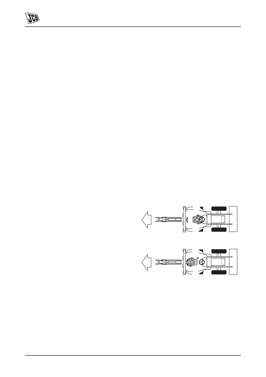
Section 1 - General Information Introduction About this Publication 1-1 1-1 9803/7130-06 Introduction About this Publication Using the Service Manual T11-004 This publication is designed for the benefit of JCB Distributor Service Engineers who are receiving, or have received, training by JCB Technical Training Department. These personnel should have a sound knowledge of workshop practice, safety procedures, and general techniques associated with the maintenance and repair of hydraulic earthmoving equipment. The illustrations in this publication are for guidance only. Where the machines differ, the text and/or the illustration will specify. General warnings in Section 2 are repeated throughout the manual, as well as specific warnings. Read all safety statements regularly, so you do not forget them. Renewal of oil seals, gaskets, etc., and any component showing obvious signs of wear or damage is expected as a matter of course. It is expected that components will be cleaned and lubricated where appropriate, and that any opened hose or pipe connections will be blanked to prevent excessive loss of hydraulic fluid and ingress of dirt. Where a torque setting is given as a single figure it may be varied by plus or minus 3%. Torque figures indicated are for dry threads, hence for lubricated threads may be reduced by one third. The manufacturer's policy is one of continuous improvement. The right to change the specification of the machine without notice is reserved. No responsibility will be accepted for discrepancies which may occur between specifications of the machine and the descriptions contained in this publication. Finally, please remember above all else safety must come first! Section Numbering T11-005 The manual is compiled in sections, the first three are numbered and contain information as follows: The remaining sections are alphabetically coded and deal with Dismantling, Overhaul etc. of specific components, for example: Section contents, technical data, circuit descriptions, operation descriptions etc. are inserted at the beginning of each alphabetically coded section. Left Side, Right Side In this manual, ‘left’ A and ‘right’ B mean your left and right when you are seated correctly in the machine. This is so whether you are facing the front or the rear. C003690 Fig 1. 1 General Information - includes torque settings and service tools. 2 Care and Safety - includes warnings and cautions pertinent to aspects of workshop procedures etc. 3 Maintenance - includes service schedules and recommended lubricants for all the machine. A Attachments B Body and Framework, etc. A B A B
Section 1 - General Information Introduction About this Publication 1-2 1-2 9803/7130-06 Machine Nomenclature In this Service Manual, reference is made to machine models, e.g. 2CX, 2CXU, these are European machine model names. North American machine models have different names, the tables below show the European and the equivalent North American nomenclature. Table 1. European: North American: 2CX 210S 2CXU 210SU
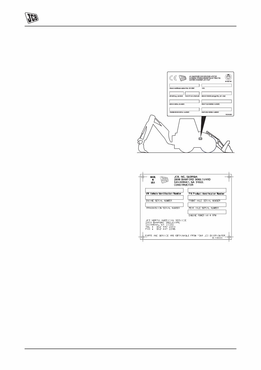
Section 1 - General Information Machine Identification Machine Identification Plate 1-3 1-3 9803/7130-8 Machine Identification Machine Identification Plate The machine has an identification plate mounted on the loader tower. The serial numbers of the machine and its major units are stamped on the plate. The serial number of each major unit is also stamped on the unit itself. If a major unit is replaced by a new one, the serial number on the identification plate will be wrong. Either stamp the new number of the unit on the identification plate, or simply stamp out the old number. This will prevent the wrong unit number being quoted when replacement parts are ordered. The machine and engine serial numbers can help identify exactly the type of equipment you have. Typical Vehicle Identification Number (VIN) 1 World Manufacturer Identification 2 Machine Model 3 Steer Type (T= 2WS, F= 4WS) 4 Build Type (S=Sideshift, C=Centremount, L=Loader) 5 Year of Manufacture: 4 = 2004 5 = 2005 6 = 2006 7 = 2007 6 Manufacturer Location (E = England) 7 Machine Serial Number T025210-1 Fig 1. U.K and R.O.W Fig 2. North America SLP 3CX T S 2 E 0960001 1 2 3 4 5 6 7
Section 1 - General Information Machine Identification Machine Identification Plate 1-4 1-4 9803/7130-8 Typical Product Identification Number (PIN) P2-1006 T016220-8 Fig 3. 1 World Manufacturer Identification (3 Digits) 2 Machine Model (5 Digits) 3 Check Letter (1 Digit) The Check Letter is used to verify the authenticity of a machine's PIN. 4 Machine Serial Number (8 Digits) Each machine has a unique serial number.
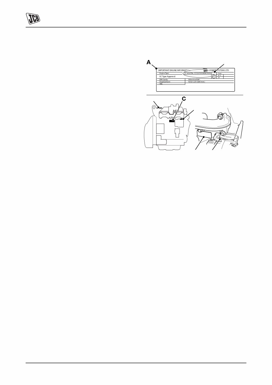
Section 1 - General Information Machine Identification Component Identification Plates 1-5 1-5 9803/7130-8 Component Identification Plates Typical Engine Identification Number Engine data labels A are located on the cylinder block at position C and rocker cover D (if fitted). The data label contains important engine information and includes the engine identification number E. A typical engine identification number is explained as follows: 1 Engine Type SA = naturally aspirated. SB = turbocharged. SC = turbocharged and intercooled. SD = turbocharged. SE = electronic common rail fuel injection, turbocharged and intercooled. SF = turbocharged and intercooled. 2 Engine part number 3 Country of manufacture U = United Kingdom 4 Engine Serial Number 5 Year of Manufacture The last three parts of the engine identification number are stamped on the cylinder block at position B. Fig 4. Engine SA 320/40001 U 00001 04 1 2 3 4 5 U 00001 04 B C D B E
Find the most complete service and repair manual for the JCB 2CX 2CXU 210S 210SU BACKHOE LOADER. This professional technical manual contains service, maintenance, and troubleshooting information for your JCB 2CX 2CXU 210S 210SU BACKHOE LOADER, making it useful for both professional mechanics and DIY enthusiasts. The manual has easy-to-read text sections with top-quality diagrams and instructions, specifically written for do-it-yourself work as well as experienced mechanics. It covers every single detail on your machine and provides step-by-step instructions based on the complete disassembly of the machine.
This manual service is packed with all the information you need and is very simple to use. Accurate, clear, and concise text combined with illustrations make it possible for anyone with even a bit of basic mechanical knowledge to safely and easily service and repair their JCB 2CX 2CXU 210S 210SU BACKHOE LOADER. Comprehensive diagrams, in-depth illustrations, and all the manufacturer's specifications and technical information you will need are included.
Whether you are using the .OVA file manual or the .PDF manual, you can find the page pertaining to your job, print it off, and get working on your machine. No more ruining your expensive paper shop manual with grease and dirt. With our able Repair Manuals, you instantly have access to the material needed to get you running again. This manual is available in English and is compatible with all versions of Windows and Mac.
JCB 2CX 2CXU 210S 210SU BACKHOE LOADER Repair Service Manual
The manual covers a wide range of topics including MOT Test Checks, Roadside Repairs, Routine Maintenance, Engine and Associated Systems, Cooling, Heating and Air Conditioning Systems, Fuel and Exhaust Systems, Engine Electrical Systems, Emissions Control Systems, Transmission, Manual Transmission, Automatic Transmission, Clutch and Driveshafts, Brakes, Braking System, Suspension, Suspension and Steering Systems, Body Equipment, Bodywork and Fittings, Electrical, Body Electrical Systems, Wiring Diagrams, Reference, Tools and Working Facilities, General Repair Procedures, Buying Spare Parts and Vehicle Identification Numbers, Fault Finding, and Glossary of Technical Terms.
Get your JCB 2CX 2CXU 210S 210SU BACKHOE LOADER FULL SERVICE MANUAL immediately! No waiting! You will have instant access to your manual. No shipping fee, no waiting nervously for the postal delivery, you can start doing your repairs right away!
Recently Viewed
5,521,897Happy Clients
2,594,462eManuals
1,120,453Trusted Sellers
15Years in Business
Price:
Actual Price:
JCB 2CX 2CXU 210S 210SU BACKHOE Loader Full Service Manual