Introduction This publication is designed for the benefit of JCB Distributor Service Engineers who are receiving, or have received, training by JCB Technical Training Department. These personnel should have a sound knowledge of workshop practice, safety procedures, and general techniques associated with the maintenance and repair of hydraulic earthmoving equipment. Renewal of oil seals, gaskets, etc., and any component showing obvious signs of wear or damage is expected as a matter of course. It is expected that components will be cleaned and lubricated where appropriate, and that any opened hose or pipe connections will be blanked to prevent excessive loss of hydraulic fluid and ingress of dirt. Finally, please remember above all else SAFETY MUST COME FIRST! The manual is compiled in sections, the first three are numbered and contain information as follows: 1 = General Information - includes torque settings and service tools. 2 = Care & Safety - includes warnings and cautions pertinent to aspects of workshop procedures etc. 3 = Routine Maintenance - includes service schedules and recommended lubricants for all the machine. The remaining sections are alphabetically coded and deal with Dismantling, Overhaul etc. of specific components, for example: A = Attachments B = Body & Framework ...etc. The page numbering in each alphabetically coded section is not continuous. This allows for the insertion of new items in later issues of the manual. Section contents, technical data, circuit descriptions, operation descriptions etc are inserted at the beginning of each alphabetically coded section. All sections are listed on the front cover; tabbed divider cards align directly with individual sections on the front cover for rapid reference. Where a torque setting is given as a single figure it may be varied by plus or minus 3%. Torque figures indicated are for dry threads, hence for lubricated threads may be reduced by one third. With the exception of slewing operations 'Left Hand' and 'Right Hand' are as viewed from the rear of the machine facing forwards. Machine Nomenclature In this Service Manual, reference is made to machine models, e.g. 2CX, 2DX, these are European machine model names. North American machine models have different names, the table below shows the European and the equivalent North American nomenclature. European North American 2CX = 210S 2DX = 213S 9803/7110 Issue 2* *
i Section 1 General Information 9803/7110 Section 1 i Issue 1 Contents Page No. Machine Identification Plate 1 - 1 Typical Machine Identification Number 1 - 1 Typical Engine Identification Number 1 - 1 Unit Identification 1 - 2 Torque Settings 2 - 1 Service Tools Numerical List 3 - 1 Service Tools Electrics 4 - 1 Hydraulics 4 - 2 Transmission 4 - 5 Engine 4 - 7 Sealing and Retaining Compounds 5 - 1
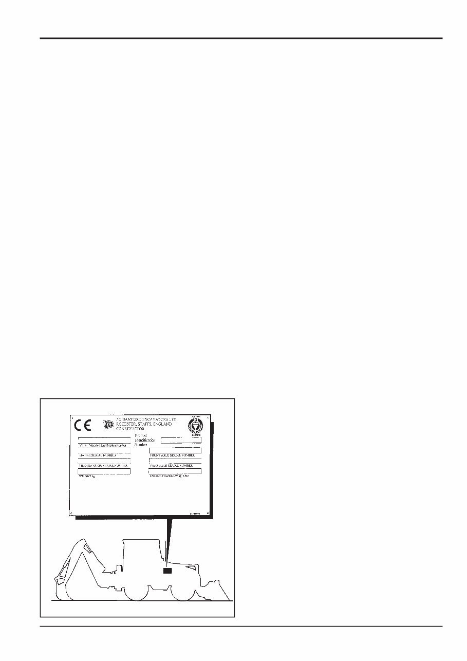
1 - 1 Machine Identification Plate Your machine has an identification plate mounted on the right hand side of the machine just below the driver's cab door. The serial numbers of the machine and its major units are stamped on the plate. The serial number of each major unit is also stamped on the unit itself. If a major unit is replaced by a new one, the serial number on the identification plate will be wrong. Either stamp the new number of the unit on the identification plate, or simply stamp out the old number. This will prevent the wrong unit number being quoted when replacement parts are ordered. The machine and engine serial numbers can help identify exactly the type of equipment you have. Typical Machine Identification Number SLP 2DX T S R E 123456 A B C D E F G A World Manufacturer Identification B Machine Model C Steer Type (T= 2WS, F=4WS) D Build Type (S=Sideshift, C=Centremount, L=Loader) E Year of Manufacture: R = 1994 1 = 2001 S = 1995 2 = 2002 T = 1996 3 = 2003 V = 1997 4 = 2004 W = 1998 5 = 2005 X = 1999 6 = 2006 Y = 2000 7 = 2007 F Manufacturer Location (E = England) G Machine Serial Number: Typical Engine Identification Number AB 50262 U 500405 P A B C D E A Engine Type AB = 4 cylinder turbo B Build Number C Country of Origin D Engine Sequence Number E Year of Manufacture Section 1 General Information 9803/7110 Section 1 1 - 1 Issue 3* S227230 * *
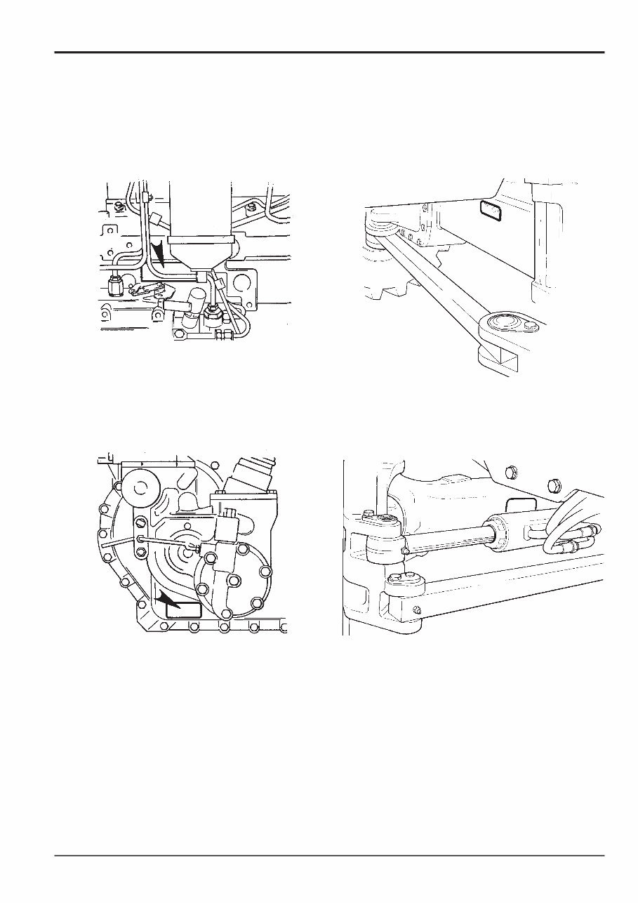
1 - 2 Unit Identification The engine serial number is stamped on a plate mounted on the left hand side of the cylinder block (looking towards the front of the machine). The rear axle serial number is stamped on a plate mounted to the front face of the axle, as shown below. The front axle serial number is stamped on a plate mounted to the rear face of the axle, as shown below. Section 1 General Information 9803/7110 Section 1 1 - 2 Issue 1 175510 175520 The Syncro Shuttle serial number is stamped on a label which is mounted to the rear face of the unit.
2 - 1 Torque Settings Use only where no torque setting is specified in the text. Values are for dry threads and may be within three per cent of the figures stated. For lubricated threads the values should be REDUCED by one third. UNF Grade 'S' Bolts Bolt Size Hexagon (A/F) Torque Settings in (mm) in Nm kgf m lbf ft 1/4 (6.3) 7/16 14 1.4 10 5/16 (7.9) 1/2 28 2.8 20 3/8 (9.5) 9/16 49 5.0 36 7/16 (11.1) 5/8 78 8.0 58 1/2 (12.7) 3/4 117 12.0 87 9/16 (14.3) 13/16 170 17.3 125 5/8 (15.9) 15/16 238 24.3 175 3/4 (19.0) 11/8 407 41.5 300 7/8 (22.2) 15/16 650 66.3 480 1 (25.4) 11/2 970 99.0 715 11/4 (31.7) 17/8 1940 198.0 1430 11/2 (38.1) 21/4 3390 345.0 2500 Metric Grade 8.8 Bolts Bolt Size Hexagon (A/F) Torque Settings (mm) mm Nm kgf m lbf ft M5 (5) 8 7 0.7 5 M6 (6) 10 12 1.2 9 M8 (8) 13 28 3.0 21 M10 (10) 17 56 5.7 42 M12 (12) 19 98 10 72 M16 (16) 24 244 25 180 M20 (20) 30 476 48 352 M24 (24) 36 822 84 607 M30 (30) 46 1633 166 1205 M36 (36) 55 2854 291 2105 Note: All bolts used on JCB machines are high tensile and must not be replaced by bolts of a lesser tensile specification. Section 1 General Information 9803/7110 Section 1 2 - 1 Issue 1
3 - 2 4104/1310 Hand Cleaner 4 - 1 The following parts are replacement items for kits and would normally be included in the kit numbers quoted on page 1/3- 1. Replacement item for kit no. 892/00180 892/00181 Replacement Plastic Boss 4 - 6 Replacement items for kit no. 892/00253 892/00201 Replacement Gauge 4 - 4 892/00202 Replacement Gauge 4 - 4 892/00203 Replacement Gauge 4 - 4 892/00254 Replacement Hose 4 - 4 Replacement items for kit no. 993/59400 993/59401 Base Plate 4 - 8 993/59402 Setting Yoke 4 - 8 993/59403 Mainshaft Adapter (long) 4 - 8 993/59404 Mainshaft Adapter (short) 4 - 8 993/59405 Ouput Yoke Adapter Plate 4 - 8 993/59406 Setting Yoke Support Pillars 4 - 8 Replacement items for kit no. 993/68100 993/68101 Slide Hammer 4 - 2A 993/68102 End Stops 4 - 2A 993/68103 Adaptor - M20 x 5/8" UNF 4 - 2A 993/68104 Adaptor - M20 x 1" UNF 4 - 2A 993/68105 Adaptor - M20 x M20 4 - 2A 993/68106 Adaptor - M20 x M24 4 - 2A 993/68107 Bar - M20 x M20 X 800MM 4 - 2A 993/68108 Adaptor - M20 x 7/8" UNF 4 - 2A 993/68109 Adaptor - M20 x M12 4 - 2A 993/68110 Adaptor - M20 x 5/8" UNF (Shoulder) 4 - 2A 993/68111 Adaptor - M20 x 1/2" UNF 4 - 2A Section 1 General Information 9803/7110 Section 1 3 - 2 Issue 2* Service Tools Numerical List (cont'd) Page No. *
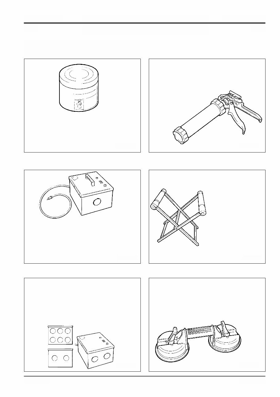
Cartridge Gun - hand operated - essential for the application of sealants, polyurethane materials etc. JCB part number - 892/00845 Service Tools Section B - Body & Framework 4 - 1 Section 1 General Information 9803/7110 Section 1 4 - 1 Issue 2 S186250 S186240 S186300 Hand Cleaner - special blend for the removal of polyurethane adhesives. JCB part number - 4104/1310 (454g; 1 lb tub) 12V Mobile Oven - 1 cartridge capacity - required to pre-heat adhesive prior to use. It is fitted with a male plug (703/23201) which fits into a female socket (715/04300). JCB part number - 992/12300 240V Static Oven - available with 2 or 6 cartridge capacity - required to pre-heat adhesive prior to use. No plug supplied. Note: 110V models available upon request - contact JCB Technical Service. JCB part number: 992/12400 - 2 Cartridge x 240V 992/12600 - 6 Cartridge x 240V Folding Stand for Holding Glass - essential for preparing new glass prior to installation. JCB part number - 892/00843 Glass Lifter - minimum 2 off - essential for glass installation, 2 required to handle large panes of glass. Ensure suction cups are protected from damage during storage. JCB part number - 892/00842 S186260 S186280 S186270
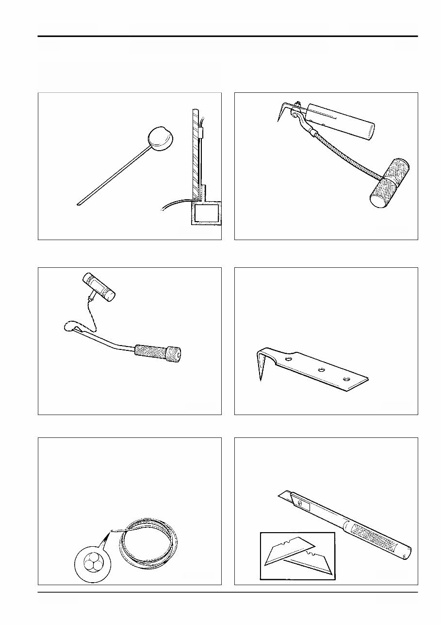
Braided Cutting Wire - consumable heavy duty cut-out wire used with the glass extraction tool (above). JCB part number - 892/00849 (approx 25 m length) Glass Extractor (Handles) - used with braided cutting wire (below) to cut out broken glass. JCB part number - 892/00846 Cut-Out Knife - used to remove broken glass. JCB part number - 992/12800 Wire Starter - used to access braided cutting wire (below) through original polyurethane seal. JCB part number - 892/00848 'L' Blades - 25 mm (1 in) cut - replacement blades for cut-out knife (above). JCB part number - 992/12801 (unit quantity = 5 off) Long Knife - used to give extended reach for normally inaccessible areas. JCB part number - 892/00844 4 - 2 Section 1 General Information 9803/7110 Section 1 4 - 2 Issue 2 Service Tools (cont'd) Section B - Body & Framework S186320 S186310 S186360 S186330 S186350 S186340
The JCB 2CX 2DX 210 212 & VARIANTS Backhoe Loader Service Manual is a comprehensive guide for the 3CX 4CX 214 215 217 models, serial numbers 930000 and 903000 onwards. This manual includes 381 pages of essential information in English, compatible with Win95/98/ME/XP/vista/7/Linux/MAC operating systems.
It covers a wide range of topics including general information, care & safety, routine maintenance, attachments, body & framework, electrics, controls, hydraulics, transmission, brakes, steering, and engine.
Our manuals are invaluable resources for both professional mechanics and DIY enthusiasts. They are available in PDF format for instant access without any shipping costs or the need to wait for a CD-ROM. If you require a specific manual that is not listed, please reach out to our customer support team via the Contact Seller link, and we will endeavor to source it for you.







 Lifetime Access




