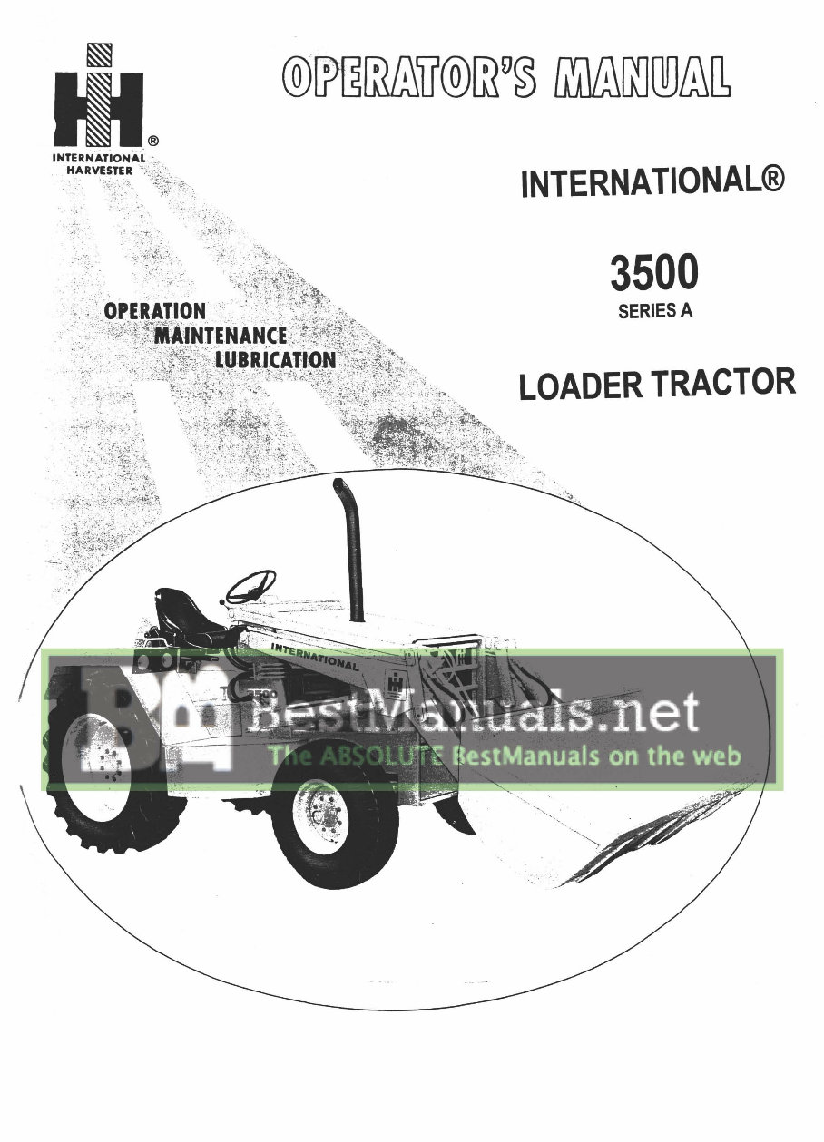
IH International 3500 Series A Loader Tractor Operators Owner Instruction Manual - IMPROVED -
What's Included?
Lifetime Access
Fast Download Speeds
Online & Offline Access
Access PDF Contents & Bookmarks
Full Search Facility
Print one or all pages of your manual
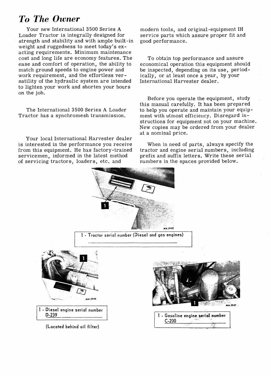
To The Owner Your new International 3500 Series A Loader Tractor is integrally designed for strength and stability and with ample built-in weight and ruggedness to meet today's ex- acting requirements. Minimum maintenance cost and long life are economy features. The ease and comfort of operation, the ability to match ground speeds to engine power and work requirement, and the effortless ver- satility of the hydraulic system are intended to lighten your work and shorten your hours on the job. The International 3500 Series A Loader Tractor has a synchromesh transmission. Your local International Harvester dealer is interested in the performance you receive from this equipment. He has factory-trained servicemen, informed in the latest method of servicing tractors, loaders, etc. and , .. ~. MA ·5946 1 • Diesel engine serial number 0·239 (Located behind oil filter) modern tools, and original-equipment IH service parts which assure proper fit and good performance. To obtain top performance and assure economical operation this equipment should be inspected, depending on its use, period- ically, or at least once a year, by your International Harvester dealer. Before you operate the equipment, study this manual carefully. It has been prepared to help you operate and maintain your equip- ment with utmost efficiellcy. Disregard in- structions for equipment not on your machine. New copies may be ordered from your dealer at a nominal price. When in need of parts, always specify the tractor and engine serial numbers, including prefix and suffix letters. Write these serial number s in the spaces provided below. MA-5942 1 • Gasol ine engine ~ri~c "UII1ber C-200 . -~ -'
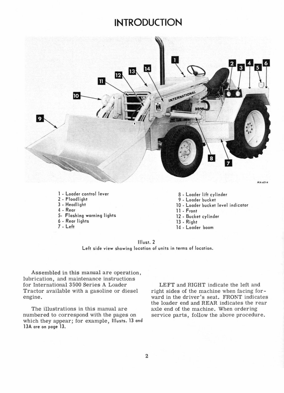
INTRODUCTION 1 • Loader control lever 2· Floodlight 3 • Heodl ight 4 • Rear S· Fla sh ing warning lights 6· Rear li ghts 7 . Left / 8· Loader lift cylinder 9 . Loader bucket 10· Loader bucket leve l indicator 11 . Fr on t 12· Buc ke t cylinder 13 . Ri ght 14 . Loader boom IoU . .oD'<II Illu st . 2 L eft side view showing location of un its in term s of location. Assembled in this manu al are operation, lubrication, and maintenance instructions for International 3500 Series A L oader Tractor available with a gasoline or diesel engine. The illustrati ons in this manual are numbered to correspon d with the pages on which they appear; for example, Illusts. 13 and 13A are on page 13. 2 LEFT and RIGHT indicate the left and right sides of the machine when facing for- ward in the driver's seat. FRONT indicates the loader e nd and REAR indicates the rear ax le end of the machine. Wh en ordering service parts, follow the above procedure .
WORK SAFELY - FOLLOW THESE RULES A T hiS symbol is used to call your attention to instruct ions concern· i ng your personal safety . Be sure to observe and follow these in- structions . A CAREFUL OPERATOR IS THE BEST INSUR· ANCE AGAINST AN ACCIDENT Kn ow the contr ols and what they do. This equipment can be dangerous if not use d properly . The operator, therefore, should de velop safe working habits and also be aware of hazardous conditions . In this way he will protect hims elf, other personnel, and the loader. Safe operation, for the most part, is the responsibility of the operator. Check coolant and engine oil levels, and per for m any other necessary services, be- for e starting the engine. When fueling an engine, keep any type of open flame away. Do not Smo ke! Wait for the engine to cool before refu eling it. Check and straighten twisted hoses. Do not attempt to repair or tighten hoses when under pressure, when the boom is raised, or with the engine running . Be sure muffler and exha ust pipe exten- sions are in place so exhaust gases are dis- charged away from the operator . Clean dirt, trash, and grease from oper - ato r's platfor m, ped als, an d steps. Do not permit anyone except the operato r on the machine. Mounting assist handles an d steps are provided for your safety . Use them when getting on or off the tractor . Avoid loose-fitting clothing, which could catch on moving parts . Before starting engine make sure helpers or observers stand clear of equipment. 3 Put all controls in stop position before starting the engine. Op erate the engine only in we ll ventilated areas . Do not transport a load with the bucket raised above transport position. Avoid sharp turns when backing up with the bucket filled and raised. Never use the loader as a battering ram. Avoid ... sudden starts, excessive speed, and sudden stops ... when operating on hill- side, rough ground, and most off -the - road operations. Use extreme care when working cl ose to fences, ditches, or on hillsides. Redu ce speed when traveling on rough roads . AVOid oper ating sideways on a steep slope whenever possible . Check clearance carefully before driving under el ect ri C lines, bridges, or entering or l eaving buildings. Use warning d evices (i. e. fl ags, S .M .V. embl em, lights, etc .) which are approved for use by your l oca l government agencies, when moving equipment on public roads. Keep these devices clean and in good working condition . Carefully sup ervise inexperien ced oper - ators . Wait for tractor to "STOP" before dis - mounting. Continue d on next page
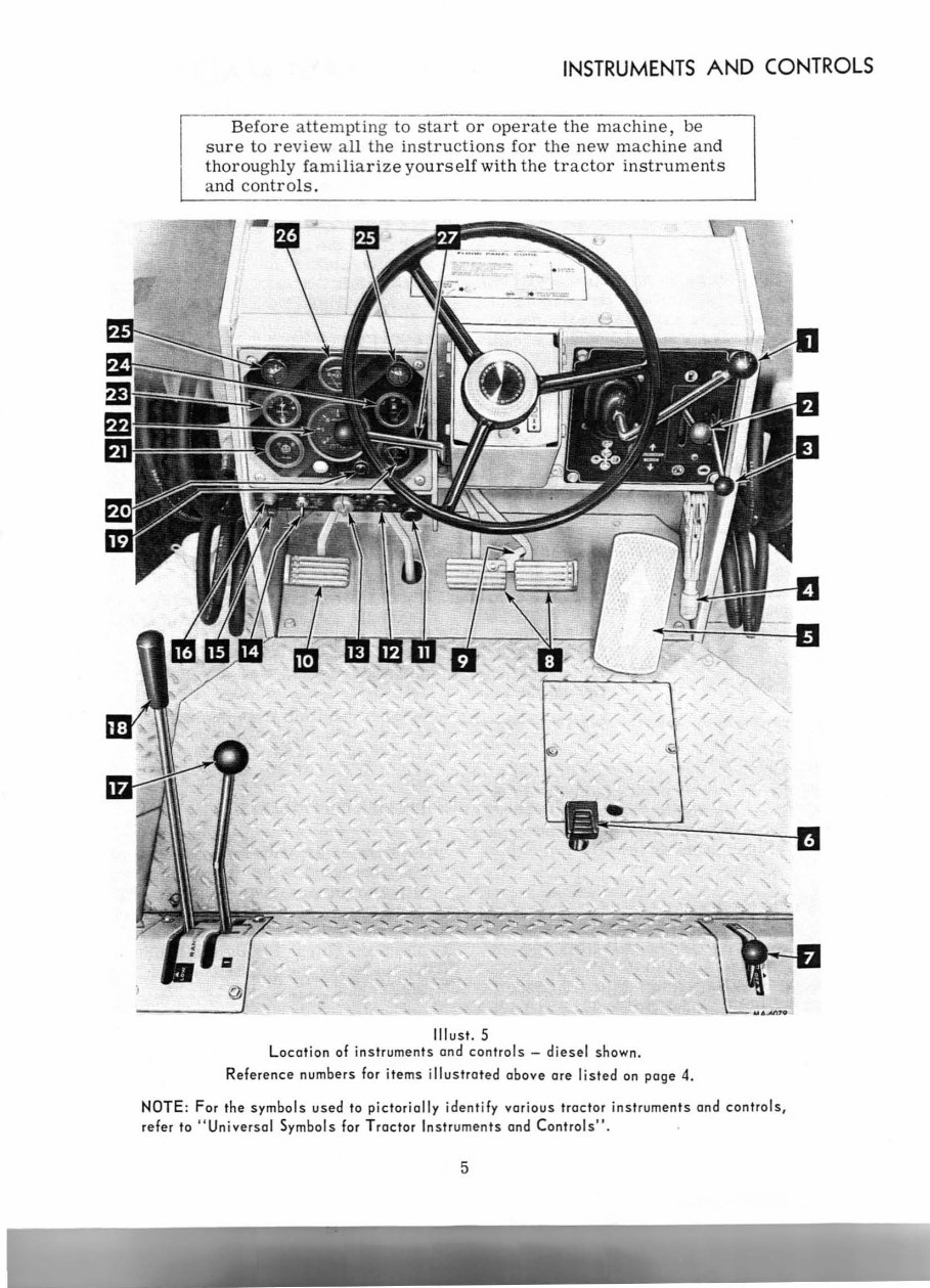
WORK SAFELY - FOLLOW THESE RULES Lock the park brake so tractor will not roll. N ever leave the machine unattended with the engine running or with the bucket in the raised position. Rest the bucket on the ground and remove the ignition key before leaving the tractor. Shut off engine and remove ignition key. Block the wheels securely, and l ower the buckets to the ground if th e machine is parked on a hillside. Stop the engine before lubri cating, clean- ing, or adjusting. If it is necessary to raise the loader boom to work on the side, or front of the machine support the boom securely. The hydraulic control l evers, or other contro l l evers, or other contro ls are not to be moved while the unit is being grease d or worked on. To r emove radiator cap when engine is " HOT", turn cap to the pressure relief pOint -l et pr es sur e and steam escape - then re - move it. Always carry a "Charge d" fire extin - guisher and a first aid kit. INSTRUMENTS AND CONTROLS Index to reference numbers for items shown in IIlust. 5. Th e items listed here are described on various pages in this manua l. Refer to " Index". 1 - Loader control l ever 2 - F-uel contro l l eve r (Di ese l) Ch oke contro l lever (Gasoline) 3 - Hand throttle co ntrol 4 - Parking hand brake 5 - Accelerator pedal 6 - Diff erentia l l ock pedal 7 - Ind ependent power take-off operating l ever 8 - Brake pedal 9 - Brake pedal l atch 10 - Clutch pedal 11 - Ci ga rette li ghte r 12 - Ether startin g push button (Di ese l) 13 - Li g hting switch 14 - Key Ignition switch 15 - Fuse holder 16 - Horn button 17 - Transmission speed lever 18 - Transmission range lever 19 - He at indicator ( coolant) 20 - Parkin g brake warning light 21 - Air cl eaner filter indicator 22 - Electronic tachometer a nd electri c hOUl· meter 23 - Ammeter 24 - Fu el gauge 25 - Instrum e nt panel li ghts 26 - Engine oil pressure gauge 27 - Forward and reverse drive l eve r Turn Signal Switch (N ot shown) Note: An anti - vanda lism cove r is used on the left instrument panel. Us e care when cl eaning the cove r to prevent scratching the surface. 4
INSTRUMENTS AND CONTROLS Before attempting to start or oper ate the mac hine , be sure to re view all the instru ct ions for the new machine an d thoroughly familiari ze yo urs e lf with the tr ac tor instruments a nd co ntr o ls. , , r / /' F r ,/ ,/ ~. , Illust. 5 " " " / Location of inst ruments and controls - diesel shown. / / " / / / / Reference numbers for items illustrated above ore listed on page 4. NOTE : For the symbols used to pictorially identify various tractor instruments and controls, refer to " Universal Symbols for Tractor Instruments and Controls ". 5
BEFORE OPERA liNG YOUR NEW MACHINE TRACTOR BREAK · IN PROCEDURE Neve r operate an engi ne imm ediate ly un- de r full l oad. Br eak it in c ar efull y as shown in the table. Do not ove rl oad the engine at any t im e. All ow engine to wa rm up bef or e ope ra ting at f ull l oad. If engine coola nt te mper at ur e r ises above r ange on te mp er at ur e gau ge, s hift to lower gear on sync hr om es h tr an s- mi s sion tr acto r. Pe ri od 1st Hour 2nd Thr ough 5th Ho ur s En gine Sp ee d Contr ol L eve r Po siti on Fully advance d Fully advance d L oad Ma in ta in engine spee d 100 RPM ab ove f ull l oad gove rn ed spee d. Full l oad go v- e rn ed spee d with occa si onal sho rt pe ri ods of li ghter l oad. Durin g fi rs t 100 hours of ope r a ti on with shipaway oil, avoid pr olonged perio ds of e n- gine idlin g, but do not ove rl oad. Hydr a uli c fil te r elem ent s mu st be c han ge d as s pec i- fied in " Lubri catio n Guid e" . GOVERNOR (Gasol i ne) Th e gove rn or is set at the f acto r y a nd sh ould r e quir e no adj ustm ent. Cons ult your In te r nati onal Ha rv es ter d ea ler if the gove r- nor doe s not f un c ti on pr ope rl y. Never ope rate the engin e at more than the regular gove rn ed sp ee d. Ex cess ive sp eed s are ha rmful. Refer to "Engine Spe eds" in the "Sp ec ifi ca ti ons". 6 Any attempt to increase the engi ne horsepower by i ncreasing engine r.p.m. above its rated ma ximum, or by other means, not only affects traveling speeds but aff ects the life of matching parts and voids the company responsibility as outlined in the warranty. LUBRICA TION Lubri cate the e ntir e tr acto r, using the " Lubri cation Guid e" and the " Lubri catio n Tabl e" for r efe r en ce . Ch ec k the o il l evels. Refer to " Lubri catio n" . PNEUMATIC TIRES Check the a ir pr ess ur es . S ee the tab les fo r fr ont a nd r ea r t ir e inflation pr ess ur es . AIR CLEANING SY STEM Refer to " Air Cl ean ing Sys tem ". ENGINE COOLING SYSTEM Never s ta rt or operate the engine with- out f irs t ch ec ki ng to see if the radi ato r is fill ed to the proper level, for the pr eva ili ng te mp erat ur e, with soft or rain water or a ntifr eeze . Refer to "Coo lin g System ". Tr acto rs shi ppe d in the Unit ed St ates and Canada h ave the cooling system f ill ed with an tifr eeze . FUEL SYSTEM Refer to "Engine and Fu el Sy st em".
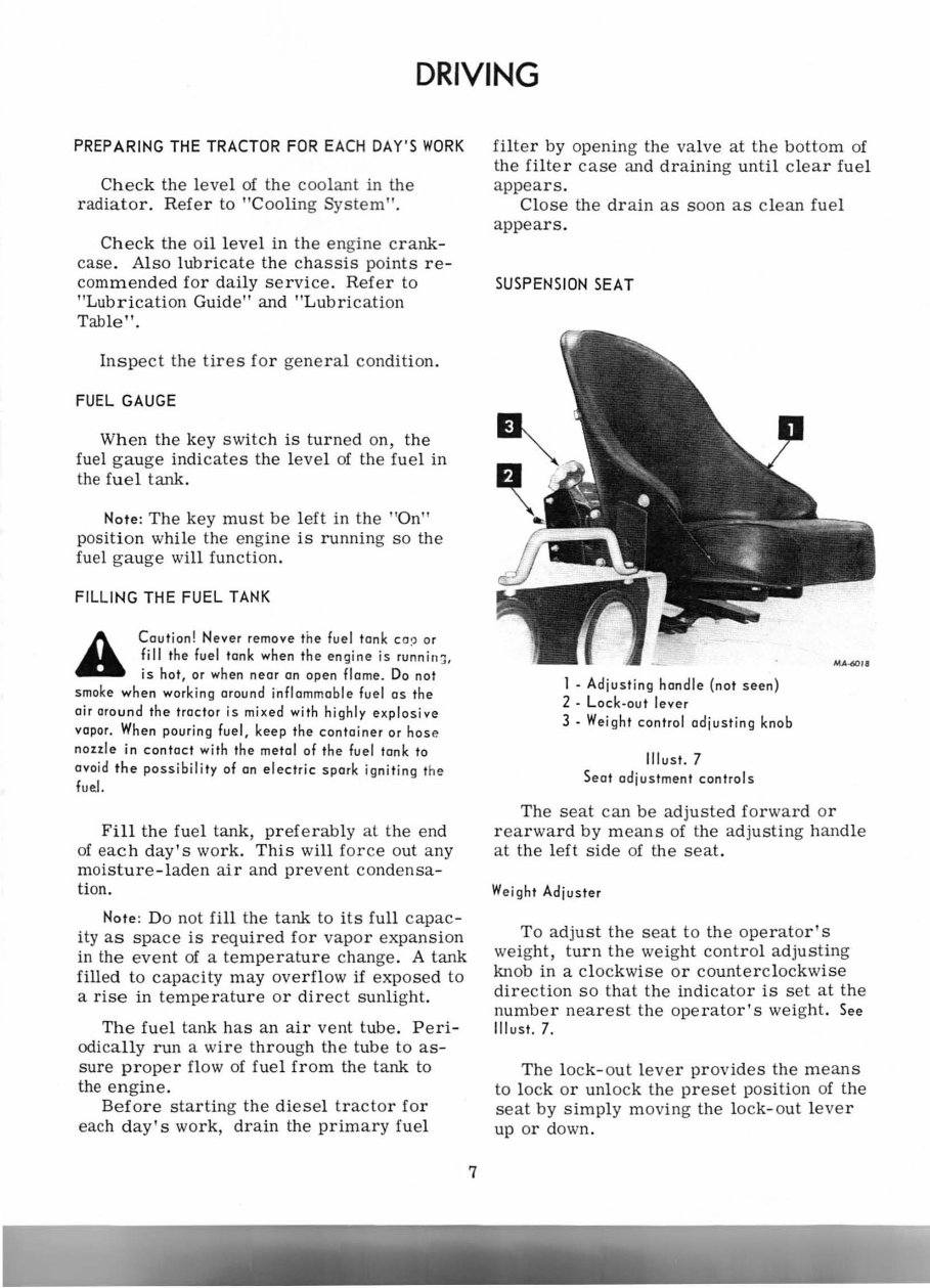
DRIVING PREPARING THE TRACTOR FOR EACH DAY'S WORK Check the l eve l of the coolant in the r adiato r. Refe r to "Cooling System". Check the oil level in the eng ine crank- case. Also lubricate the chassis points re- commended for daily service. Refer to "Lubrication Guide" and "Lubrication Table" . Inspect the tires for gen eral condit ion. FUEL GAUGE When the key switch is turned on, the fuel gauge indicates the level of the fuel in the fuel tank. Note: The key must be left in the "On" pos ition while the engine is runnin g so the fuel gau ge will function. FILLING THE FUEL TANK A Caution! Never remove the fuel tonk CO,) or fill the fuel tank when the engine is ru~niI1 J, is hot, or when near an open flome. Do not smoke when working around inflammable fuel as the air around the tractor is mixed with highly explosive vapor. When pouring fuel, keep the container or hose nozzle in contact with the metal of the fuel lank to ovoid the possibility of on electric spark igniting the fuel. Fill the fuel tank, pref e rably al the end of eac h day's work. This will force out any moisture -l aden air and prevent co nd ensa - tion. Note: Do not fill the tank to i ts full capac - ity as space is r equire d for vapor expans ion in the eve nt of a temperature change. A tank filled to capacity may overflow if expo sed to a rise in temperature or direct sunli ght. The fuel tank has an air vent tube. Peri- odically run a wire through the tube to as- sure prope r flow of fuel from the tank to the engine. Before starting the dies el t ra cto r for each day 's work, drain the primary fuel 7 filter by opening the valve at the bottom of the filter case and draining unt il clear fuel appea rs. Close the drain as soon as cl ean fuel appears. SUSPENSION SEAT I - Adjusting handle (not seen) 2 - Loc k-aut lever 3 - We ight control adjusting knob Illust. 7 Seat adjustment controls The seat can be adjusted forward or rearward by means of the adjusting handle at the l eft side of the seat. Weight Adjuster To adjust the seat to the ope r ato r's weight, turn the weight cont rol adjusting knob in a clockwise or counterclockwise direction so that the indicator is set at the number nearest the ope rat o r's weight. See Illusl. 7. The loc k- out l eve r provides the means to lock or unl ock the preset position of the seat by simply moving the l ock-out l eve r up or down.
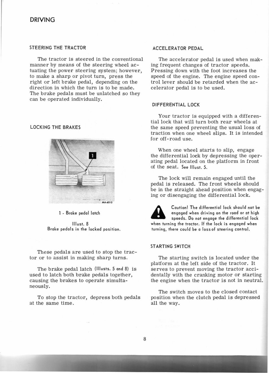
DRIVING STEER ING THE TRACTOR The tractor is steered in the conventional manner by means of the steering wheel ac - tuating the power steering system ; however, to make a sharp or pivot t urn , press the right or l eft brake pedal, depending on the direction in which the turn is to be made . The brake pedals must be unlatched so they can be operated individually. LOCKING THE BRAKES MA-60J3 1 . Br oke pedal latch II lust. 8 Bro ke pedals in the locked position. Th ese pedals a re us ed to stop the trac- tor or to assist in making sharp turns. The brake pedal latch (lllusts. 5 and 8) is us ed to lat ch both brake pedals toget h er, causing the brakes to operate simulta- neously . To stop the tractor, depress both pedals at the same time. 8 ACCELERATOR PEDAL The accelerator pedal is used when mak- ing frequent changes of tractor speeds. Pressing down with the foot increases the speed of the engine. The eng ine speed con- trol l eve r should be retarded when the ac- cele r ato r peda l is to be used. DIFFERENTIAL LOCK Your tractor is equipped with a differen- tia l lock that will turn both rear wh e els at the same speed preventing the usual loss of traction when one wheel slips. It is intended for off -r oad use . When one wheel starts to slip, engage the differential l ock by depressing the oper- ating pedal l ocated on the platform in front of the seat. See Illu st. 5. The l ock will remain engaged until the pedal is released. The front wheels should be in the straight ahead position when engag- ing or disengaging the differential l ock . Caution! The differential lock should not be engaged when driving on the rood or at high speeds. Do not engage t he differential lock when t urnin g the tractor. If the lo ck is engaged when turning, there could be a loss of steering control. ST ARTING SWI TCH The starting switch is l ocated under the platf orm at the l eft side of the tractor . It serves to prevent moving the tractor acci - dentally with the cranking motor or starting the engine when the tractor is not in neutral. The switch moves to the cl osed contact position when the clutch pedal is depressed al l the way.
This manual is a comprehensive guide for IH International Factory 3500 Series A Loader Tractor owners and operators. It contains detailed instructions, diagrams, and illustrations based on the manufacturer's specifications. The improved manual features bookmarks, searchable text, an index, and enhanced quality.
It is an essential resource for both professional mechanics and DIY enthusiasts, covering various aspects of operating and maintaining the Loader Tractor. The manual includes sections on safety guidelines, instrument and control operation, engine and fuel systems, power take-off, cooling and air cleaning systems, electrical system, tires, lubrication, preventive maintenance, specifications, optional equipment, and more.
Presented in an easy-to-read format, this manual is compatible with all versions of Windows, Mac, iOS, BB, Android, and more. It is searchable, bookmarked, and indexed for quick access to information. The document is complete with numerous pictures, diagrams, illustrations, and charts, making it suitable for viewing on any computer, with the ability to zoom in, print, and save pages as needed.
For those in need of technical details and instructions, this manual provides all the necessary information. It is a valuable resource for troubleshooting and workshop maintenance. Please note that this is a .PDF manual, not interactive software.
For any inquiries about this or other manuals, feel free to reach out. Please ensure you have the latest version of Adobe Acrobat Reader for optimal viewing of the document.
Introduction
Work Safely - Follow these Rules
Instruments and Controls
Before Operating Your New Machine
Driving
Operating The Loader
Gasoline Engine and Fuel System
Diesel Engine and Fuel System
Power Take-Off
Cooling System
Air Cleaning System
Electrical System
Wheels
Pneumatic Tires
Rear Counterweight
Storing the Machine
Cold Weather Precautions
Lubrication
Lubrication Table
Lubrication Guide
Preventive Maintenance Guide
Specifications
Optional Equipment
Universal Symbols for Tractor Instruments and Controls
Index
Recently Viewed
5,521,897Happy Clients
2,594,462eManuals
1,120,453Trusted Sellers
15Years in Business
Price:
Actual Price:
IH International 3500 Series A Loader Tractor Operators Owner Instruction Manual - IMPROVED -