FOREWARD This manual has been prepared to assist you in the proper break-in, daily care, and operation of your new Ford 550 Tractor-Loader or Tractor-Loader-Backhoe. It contains specific informa- tion on its many features; the attachments that are available; instructions for making minor repairs and adjustments; safety precautions; general specifications; suggested operating techniques; the pre-delivery and 50 hour check lists. Your Ford 550 has been carefully inspected before leaving the factory and by your Ford Tractor-Equipment Dealer prior to delivery to see that it is "ready to go." To keep it in this "ready to go" condition, it is important to follow regularly scheduled service periods as recom- mended in this manual. Any references to right, left, front or rear, when referring to the loader or tractor portions of the Ford 550, is as viewed from the operator's seat when the seat is facing forward for forward travel. When referring to the backhoe portion of the Ford 550, all references to left and right are as viewed from the operator's seat while facing rearward, which is normal for backhoe operation. The Ford 550 serial number is important should your unit require future service. Have your Dealer record this number, along with the other information called for in the spaces below. Read this manual carefully before operating your Ford 550 and keep it in a convenient location for future reference. If, at any time, you have a service problem concerning your new Ford 550, remember that your Ford Tractor-Equipment Dealer has factory trained service personnel, genuine Ford parts, and the necessary tools and equipment to best satisfy your service needs. Ford Tractor 0 perati ons Ford Motor Company ISSUED TO: ISSUED BY: Owner's Name Ford Tractor-Equipment Dealer Mailing Address City City State Zip Code State Zip Code Delivery Date Ford 550 Serial Number Backhoe Serial Number (If Equipped)
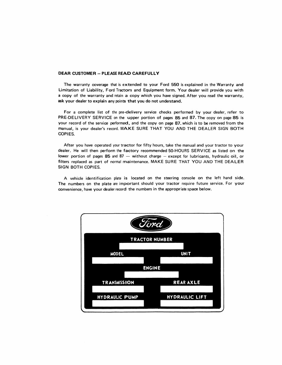
DEAR CUSTOMER - PLEASE READ CAREFULL V The warranty coverage that is extended to your Ford 550 is explained in the Warranty and Limitation of Liability, Ford Tractors and Equipment form. Your dealer will provide you with a copy of the warranty and retain a copy which you have signed. After you read the warranty, ask your dealer to explain any points that you do not understand. For a complete list of the pre-delivery service checks performed by your dealer, refer to PRE·DELIVERY SERVICE on the upper portion of pages 85 and 87. The coPy on page 85 is your record of the service performed, and the copy on page 87. which is to be removed from the manual, is your dealer's record. MAKE SURE THAT YOU AND THE DEALER SIGN BOTH COPIES. After you have operated your tractor for fifty hours, take the manual and your tractor to your dealer. He will then perform the factory recommended 50·HOURS SERVICE as listed on the lower portion of pages 85 and 87 - without charge - except for lubricants, hydraulic oil, or filters replaced as part of normal maintenance. MAKE SURE THAT YOU AND THE DEALER SIGN BOTH COPIES. A vehicle identification plate is located on the steering console on the left hand side. The numbers on the plate are important should your tractor require future service. For your convenience, have your dealer record the numbers in the appropriate space below.
CONTENTS Safety Precautions 2 Controls and Instruments 3 general 4 brake and rear axle controls 11 transmission controls 12 loader controls 12 backhoe controls 13 Operation 17 break-in procedures 18 starting the engine 18 transmission operation 18 towing and transporting 22 weighting limitations 23 loader operation 25 backhoe operation 31 loader and backhoe attachments 41 backhoe and counterweight removal and installation 44 Lubrication and Maintenance 49 lubrication and maintenance chart 50 fuels and lubricants 51 fuel and lubricant service procedures 52 general maintenance 62 hydraulic hoses and tubing 74 storing the Ford 550 74 Specifications 77 pre-delivery and 50-hour service 85 1
2 SAFETY PRECAUTIONS A careful operator is the best operator. Most accidents can be avoided by observing certain precautions to prevent the possibility of injury or damage. The following precau· tions are suggested to help prevent accidents. Read them carefully before operating your new Ford 550. 1. Read this manual carefully to acquaint yourself with the Ford 550. Working with unfamilair equipment can lead to accidents. 2. Use the hand holds when getting on and off the Ford 550. 3. For safe operation, observe proper maintenance and repair of all pivot pins, hydraulic cylinders, hoses, snap rings, and main attaching .bolts prior to each day 's opera· tion . 4. If the unit is equipped with a rollbar or safety cab,al ways fasten the seat belt before starting the engine. 5. Keep the operator's platform free of debris . 6. Do not bypass the safety starter switch . Consult your Ford Tractor·Equipment Dealer if your safety starter controls are malfunctioning. 7. Always be sure of water , gas, sewage, and electrical line locations before you start to dig. 8. Never start the engine while standing beside the unit. Always start the engine while sitting in the operator's seat. 9. Never run the engine in a closed building without ade· quate ventilation, as the exhaust fumes are very danger· ous. 10. Do not permit anyone to ride on the Ford 550 with the operator. 11. Operate the loader or backhoe controls only when pro- perly seated at the controls. 12. Never attempt to lift loads in excess of loader or back- hoe capacity . 13. Never allow anyone to get under the loader or back· hoe buckets, or reach through the lift arms when the buckets are raised. 14. Always be watchful of bystanders when operating the loader, when lowering the stabilizers, or when opera- ting the backhoe. 15. Use care when operating on steep grades to mai ntain proper stability, also drive at speeds compatible with safety, especially when operating over rough ground, crossing ditches, slopes, or when turning. 16. To prevent upsets, avoid full reach and swinging a loaded backhoe bucket to the downhill side when operating on a slope . it means: 17. Watch out for overhead and underground high-voltage electrical lines when operating the backhoe. 18. Exercise caution when operating the loader with a raised loaded bucket or fork . 19. Always carry the loader bucket low for maximum sta- bility and visibility, whether the bucket is loaded or empty. 20. Always use the headlamps and work lamps for night work . 21 . Always lower the loader and backhoe buckets to the ground, shut off the engine and apply the parking brake before getting off the unit . Never get off the unit while it is in motion . 22. Always apply the parking brake and remove the starter key when leaving the unit parked or unattended. 23. Never leave the unit when it is parked on an incline. Always park the unit on level ground where possible. If the unit is to be parked on an incline, always lower the buckets so that the cutting lips contact the ground, apply the parking brake, and securely block the wheels. 24. Always che,;k overhead clearance, especially when trans· porting the unit. 25. Always attach the backhoe transport chains before transporting the Ford 550. 26. Never attach chains, ropes, cables, etc., to the ROPS or cab for pulling purposes, as the unit can tip rearward. 27. When necessary to tow the Ford 550, do not exceed 5 mph (8 kphl. 28. When traveling on public roads, use accessory lights and devices for adequate warning to operators of other vehicles. 29 . Do not lubricate or make mechanical adjustments while the unit is in motion or when the engine is running. However, if minor engine adjustments must be made, apply the parking brake, securely block the wheels, and use extreme caution. Be certain that the loader is fully lowered or supported so that it can not fall. 30. Never make repairs or tighten hydraulic hoses or fit- tings when the system is under pressure, when the engine is running, or when the loader or backhoe cylinders are under a load. 31. Never refuel the Ford 550 while smoking or when the engine is hot or running . 32. Always keep the brakes and power steering system in good operating condition . Whenever you see th;s symbol A ATTENTION! BECOME ALERT! YOUR SAFETY IS INVOLVED!
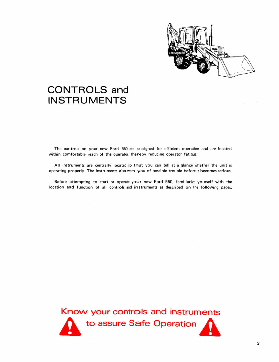
CONTROLS and INSTRUMENTS The controls on your new Ford 550 are designed for efficient operation and are located within comfortable reach of the operator, thereby reducing operator fatigue. All instruments are centrally located so that you can tell at a glance whether the unit is operating properly . The instruments also warn you of possible trouble before it becomes serious. Before attempting to start or operate your new Ford 550, familiarize yourself with the location and function of all controls and instruments as described on the following pages. Knovv your controls and instruments A to assure Safe Operation A 3
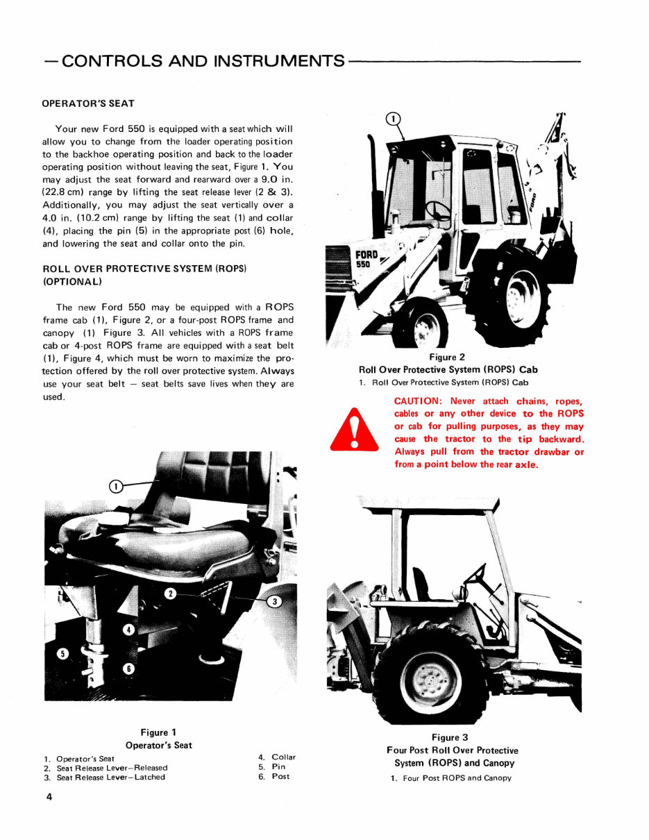
- CONTROLS AND INSTRUMENTS ---------- OPERATOR'S SEAT Your new Ford 550 is equipped with a seat wh ich will allow you to change from the loader operating position to the backhoe operating position and back to the loader operating position without leaving the seat, Figure 1. You may adjust the seat forward and rearward over a 9.0 in . (22.8 cm) range by lifting the seat release lever (2 & 3). Additionally, you may adjust the seat vertically over a 4 .0 in . (10.2 cm) range by lifting the seat (1) and collar (4), placi ng the pin (5) in the appropriate post (6) hole, and lowering the seat and collar onto the pin. ROLL OVER PROTECTIVE SYSTEM (ROPS) (OPTIONAL) The new Ford 550 may be equipped with a R OPS frame cab (1), Figure 2, or a four-post ROPS frame and canopy (1) Figure 3. All vehicles with a ROPS frame cab or 4-post ROPS frame are equipped with a seat belt (1), Figure 4, which must be worn to maximize the pro· tection offered by the roll over protective system. Always use your seat belt - seat belts save lives when they are used . 1. Operator 's Seat Figure 1 Operator's Seat 2. Seat Release Lever-Released 3. Seat Release Lever-Latched 4 4. COllar 5. Pin 6. Post Figure 2 Roll Over Protective System (ROPS) Cab 1. Roll Over Protective System (RaPS) Cab CAUTION : Never attach chains, ropes, cables or any other device to the ROPS or cab for pulling purposes, as they may cause the tractor to the tip backward. Always pull from the tractor drawbar or from a point below the rear axle. Figure 3 Four Post Ro" Over Protective System (ROPS) and Canopy 1. Four Post RaPS and Canopy
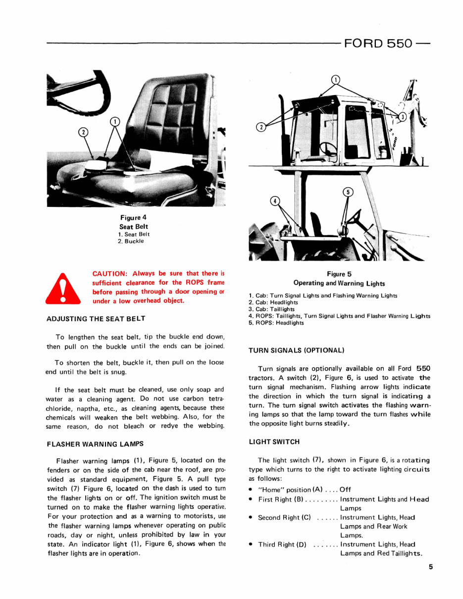
------------------ FORD 550- Figure 4 Seat Belt 1. Seat Belt 2. Buckle CAUTION: Always be sure that there is sufficient clearance for the ROPS frame before passing through a door opening or under a low overhead object. ADJUSTING THE SEAT BELT To lengthen the seat belt, tip the buckle end down, then pull on the buckle until the ends can be joined. To shorten the belt, buckle it, then pull on the loose end unti I the belt is snug. If the seat .belt must be cleaned, use only soap and water as a cleaning agent. Do not use carbon tetra· chloride, naptha, etc ., as cleaning agents, because these chemicals will weaken the belt webbing. Also, for the same reason, do not bleach or redye the webbing. FLASHER WARNING LAMPS F lasher warning lamps (1), Figure 5, located on the fenders or on the side of the cab near the roof, are pro· vided as standard equipment, Figure 5. A pull type switch (7) Figure 6, located on the dash is used to turn the flasher lights on or off . The ignition switch must be turned on to make the flasher warning lights operative. For your protection and as a warning to motorists, use the flasher warning lamps whenever operating on public roads, day or night, unless prohibited by law in your state. An indicator light (1), Figure 6, shows when the flasher lights are in operation . Figure 5 Operating and Warning lights 1. Cab: Turn Signal Lights and Flashing Warning Lights 2. Cab: Headlights 3. Cab: Taillights 4. ROPS: Taillights, Turn Signal Lights and Flasher Warning Lights 5. ROPS : Headlights TURN SIGNALS (OPTIONAL) Turn signals are optionally available on all Ford 550 tr!'lctors. A switch (2), Figure 6, is used to activate the turn signal mechanism. Flashing arrow lights indicate the direction in which the turn signal is indicating a turn. The turn signal switch activates the flashing warn- ing lamps so that the lamp toward the turn flashes while the opposite light burns steadily. LIGHT SWITCH The light switch (7), shown in Figure 6, is a rotating type which turns to the right to activate lighting circuits as follows: • "Home" position (A) .... Off • First Right (8) ..... .... Instrument Lights and Head Lamps • Second Right (e) ... .. . Instrument Lights, Head Lamps and Rear Work Lamps. • Third Right (D) .. _ .. .. Instrument Lights, Head Lamps and Red Taillights. 5
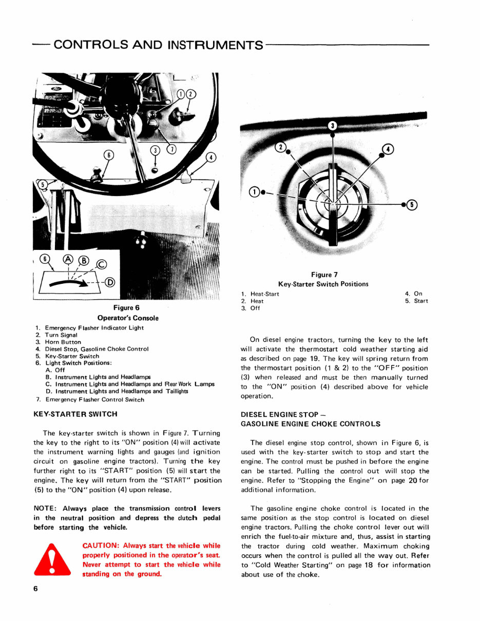
- CONTROLS AND INSTRUMENTS---------- Figure 6 Operator's Console 1. Emergency Flasher Indicator Light 2. Turn Signal 3. Horn Button 4. Diesel Stop, Gasoline Choke Control 5. Kev-Starter Switch 6. Light Switch Positions; A. Off B. Instrument Lights and Headlamps C. Instrument Lights and Headlamps and Rear Work Lamps D. Instrument Lights and Headlamps and Taillights 7. Emergency F lasher Control Switch KEY-STARTER SWITCH The key·starter switch is shown in Figure 7. Turning the key to the right to its "ON" position (4) will activate the instrument warning lights and gauges (and ignition circuit on gasoline engine tractors). Turning the key further right to its "START" position (5) will start the engine. The key will return from the "START" position (5) to the "ON" position (4) upon release. NOTE: Always place the transmission control levers in the neutral position and depress the clutch pedal before starting the vehicle, 6 CAUTION: Always start the vehicle while properly positioned in the operator's seat. Never attempt to start the vehicle while standing on the ground. Figure 7 Key·Starter Switch Positions 1. Heat·Start 4. On 2. Heat 5. Start 3. Off On diesel engine tractors, turning the key to the left will activate the thermostart cold weather starting aid as described on page 19. The key will spring return from the thermostart position (1 & 2) to the "OFF" position (3) when released and must be then manually turned to the "ON" position (4) described above for vehicle operation. DIESEL ENGINE STOP- GASOLINE ENGINE CHOKE CONTROLS The diesel engine stop control, shown in Figure 6, is used with the key- starter switch to stop and start the engine. The control must be pushed in before the engine can be started. Pulling the control out will stop the engine. Refer to "Stopping the Engine" on page 20 for additional information. The gasoline engine choke control is located in the same position as the stop control is located on diesel engine tractors. Pulling the choke control lever out will enrich the fuel-to-air mixture and, thus, assist in starting the tractor during cold weather. Maximum choking occurs when the control is pulled all the way out. Refer to "Cold Weather Starting" on page 18 for information about use of the choke _
This complete factory Ford New Holland 550 Tractor Loader Backhoe Owners, Operators Manual provides detailed instructions, diagrams, and illustrations based on the manufacturer's specifications. It is useful for both professional mechanics and DIY enthusiasts.
Model 550 indicates 3 cylinder tractor loader backhoes produced in 1975, 1976, 1977, and 1978.
An Operators Manual covers many aspects of operating and maintaining the machine.
Contents include safety precautions, controls & instruments, operation, lubrication & maintenance, and specifications.
This manual is clear and written in a way so that just about anybody can follow it. It is available in an easy-to-read file format and can be viewed on any computer, as well as zoomed and printed. Additionally, it is completely searchable & bookmarked, making it easy to find what you are looking for. The manual includes lots of pictures, diagrams, illustrations, and charts, along with technical details and instructions.
Language: English
Format: PDF
Compatibility: All Versions of Windows, Mac, iOS, BB, Android, etc
Additional Information: Documents may require the newest version of Acrobat Reader to display correctly. Should you have any problems reading your document, please initially try upgrading to the latest version of Adobe Acrobat Reader.
If you have any questions or need other manuals, feel free to email for assistance.