Case 580N, 580SN-WT, 580SN, 590SN Tractor Loader Backhoes OEM Service & Repair Manual
What's Included?
Lifetime Access
Fast Download Speeds
Online & Offline Access
Access PDF Contents & Bookmarks
Full Search Facility
Print one or all pages of your manual
Part number 84516378 English July 2011 Replaces part number 84390833 SERVICE MANUAL 580N 580SN-WT 580SN 590SN Tractor Loader Backhoe
Contents INTRODUCTION HYDRAULIC, PNEUMATIC, ELECTRICAL, ELECTRONIC SYSTEMS A PRIMARY HYDRAULIC POWER SYSTEM .............................................. A.10.A SECONDARY HYDRAULIC POWER SYSTEM.......................................... A.12.A ELECTRICAL POWER SYSTEM ........................................................ A.30.A FAULT CODES ........................................................................... A.50.A ENGINE AND PTO IN ................................................................... B ENGINE .................................................................................. B.10.A FUEL AND INJECTION SYSTEM ........................................................ B.20.A EXHAUST SYSTEM...................................................................... B.40.A ENGINE COOLANT SYSTEM ........................................................... B.50.A STARTING SYSTEM ..................................................................... B.80.A TRANSMISSION, DRIVE AND PTO OUT ........................................ C TRANSMISSION Power Shuttle .......................................................... C.20.C TRANSMISSION Powershift ............................................................. C.20.E AXLES, BRAKES AND STEERING................................................. D FRONT AXLE ............................................................................ D.10.A REAR AXLE .............................................................................. D.12.A STEERING Hydraulic..................................................................... D.20.C SERVICE BRAKE Hydraulic.............................................................. D.30.C PARKING BRAKE Mechanical ........................................................... D.32.B WHEELS AND TRACKS Wheels......................................................... D.50.C FRAME AND CAB ........................................................................ E FRAME Primary frame ................................................................... E.10.B SHIELD ................................................................................... E.20.A USER CONTROLS AND SEAT .......................................................... E.32.A USER CONTROLS AND SEAT Operator seat ........................................... E.32.C USER PLATFORM ....................................................................... E.34.A 84516378 05/07/2011
ENVIRONMENT CONTROL Air-conditioning system .................................... E.40.C FRAME POSITIONING ................................................................. F STABILISING Working stabilising ........................................................ F.20.D TOOL POSITIONING .................................................................... G LIFTING .................................................................................. G.10.A HITCH AND WORKING TOOL ....................................................... H BOOM Lift ................................................................................ H.20.B BOOM Swing ............................................................................. H.20.D DIPPER Lift ............................................................................... H.25.B DIPPER Extension ....................................................................... H.25.F ARM TOOL ATTACHMENT Tilt........................................................... H.30.C EXCAVATING AND LANDSCAPING ............................................... J DIGGING Non-articulated digging tools .................................................. J.20.B CARRYING Articulated tools ............................................................. J.50.C 84516378 05/07/2011
INTRODUCTION Safety rules DANGER Improper operation or service of this machine can result in an accident. Do not operate this machine or perform any lubrication, maintenance, or repair on it until you have read and understood the operation, lubrication, maintenance, and repair information. Failure to comply will result in death or serious injury. D0010A WARNING Maintenance hazard! Always perform all service procedures punctually at the intervals stated in this manual. This ensures optimum performance levels and maximum safety during machine operation. Failure to comply could result in death or serious injury. W0132A WARNING Pressurized system! Before attempting any service procedure, it is your responsibility to know the number of accumulators on the machine, and the correct procedure for releasing the pressure of each accumulator. Failure to comply could result in death or serious injury. W0136A NOTICE: Extreme working and environmental conditions require shortened service intervals. Use Case fluids, lubricants, and filters for the best protection and performance of your machine. All fluids, lubricants, and filters must be disposed of in compliance with environmental standards and regulations. Contact your dealer with any questions regarding the service and maintenance of this machine. Read the safety decals and information decals on the machine. Read the Operator’s Manual and safety manual. Understand the operation of the machine before you start any service. Before you service the machine, put a 'Do Not Operate' tag on the steering wheel or over the key switch. Ensure the tag is at a location where everyone who might operate or service the machine may see clearly. One tag is included with your new machine. Additional tags are available from your dealer. Plastic and resin parts • Avoid using gasoline, paint thinner, etc. when cleaning plastic parts, console, instrument cluster, etc. • Use only water, mild soap, and a soft cloth when you clean these parts. • Using gasoline, thinners, etc. can cause discoloration, cracking, or deformation of the part being cleaned. 84516378 05/07/2011 3
INTRODUCTION Safety rules Before you weld, cut, or drill holes on any part of this machine, make sure the part is not cast ductile iron. See your dealer if you do not know if a part is cast ductile iron. The following are cast ductile iron parts: • two wheel drive steering link • dump links • front axle • stabilizers • extendable dipper • swing tower • bucket linkage Unauthorized modifications to cast ductile iron parts can cause injury or death. Welding, cutting, or drilling can cause cast ductile iron to break. Do not weld, cut, or drill to repair or to attach items to cast ductile iron parts on this machine. 84516378 05/07/2011 4
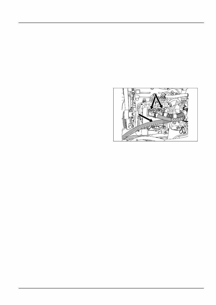
INTRODUCTION Safety rules Before welding on the machine you must do the following. If you have any questions about welding on the machine contact your dealer. • Disconnect the batteries. • Disconnect the alternator terminal wires. • Disconnect the instrument cluster. • One connector for mechanical fuel injection engines. • Two connectors for HPCR (high pressure common rail) engines. • Disconnect the engine control unit (ECU), if equipped (three connectors). NOTE: The third connector is behind the hose in the illustration. RCPH10TLB046AAF 1 • Disconnect the controller for backhoe pilot controls, if equipped (one connector). • Disconnect the transmission controller, if equipped (one connector, located under the front steering cowling). • Disconnect the controller for the loader 4 in 1 bucket or auxiliary hydraulics, if equipped (one connector, located under the loader valve at the rear, left un- derside of the machine). 84516378 05/07/2011 5
INTRODUCTION Safety rules Unless otherwise instructed, always perform these steps before you service the machine: 1. Park the machine on a flat, level surface. 2. Place the backhoe in the transport position with the swing lock pin installed for transport. 3. Place the loader bucket on the ground, with the bottom of the loader bucket parallel to the surface. 4. Place the direction control lever and the transmission in neutral. 5. If you need to open the hood to perform service, raise the loader arms and install the support strut. 6. Shut down the engine. 7. Place a 'Do Not Operate' tag on the key switch so that it is visible to other workers or remove the key. 84516378 05/07/2011 6
Case 580N, 580SN-WT, 580SN, 590SN Tractor Loader Backhoes OEM Service & Repair Manual
Models covered:
Case 580N
Case 580SN-WT
Case 580SN
Case 590SN
Keeping a backhoe loader running smoothly demands precision, and this Case 580N, 580SN-WT, 580SN, 590SN Tractor Loader Backhoes OEM Service & Repair Manual delivers exactly that. Whether it's diagnosing hydraulic pressure issues or servicing the transmission, this factory-issued guide provides the technical data needed to get the job done right.
This manual covers everything from backhoe and loader adjustments to engine overhauls, ensuring every repair meets manufacturer specifications. With detailed breakdowns of hydraulic flow rates, torque specs, and service intervals, it helps mechanics and operators stay ahead of wear and tear. Keeping up with these factory-recommended procedures not only prevents downtime but also maximizes machine lifespan in demanding conditions.
For those tackling maintenance or repairs on a Case 580N series or 590SN backhoe, this manual is a must-have reference. Whether in the shop or on the job site, it ensures each service task is performed to OEM standards for reliability and performance.
Printable: Yes Language: English Compatibility: Pretty much any electronic device, incl. PC & Mac computers, Android and Apple smartphones & tablet, etc. Requirements: Adobe Reader (free)
Recently Viewed
5,521,897Happy Clients
2,594,462eManuals
1,120,453Trusted Sellers
15Years in Business
Price:
Actual Price:
Case 580N, 580SN-WT, 580SN, 590SN Tractor Loader Backhoes OEM Service & Repair Manual