Form No. 913209 Rev B Replaces 907875 PARTS MANUAL 1438 1448 (Serial Numbers 18100 and Before) Power Box ® Self-Propelled Paver ®
Introduction 1438/1448 Power Box The Table of Contents lists the page location of vari- ous component groups on the machine. When ordering service parts, specify the correct part number, full description, quantity required, and the unit model and serial number. Serial numbers for this unit are stamped on a plate located on top of the control panel housing. The seri- al number is also stamped on the left top backwall plate. The following reference shows the breakdown of the serial number: “Right” and “left” are determined from a position standing behind the screed and facing the machine. GEHL Company reserves the right to make changes or improvements in the design or construction of any part of the unit without incurring the obligation to install such changes on any unit previously delivered. If grease fittings and common attaching hardware, such as cotter pins, set screws, woodruff keys, screws, nuts, etc., are not illustrated, they may be in the parts list indented below the part they are associated with. The hardware listed is for mounting purposes and is NOT included when the part is ordered for replace- ment. Standard attaching hardware torque values are pro- vided on the inside back cover. Unless otherwise specified, all capscrews are Grade 5, cadmium or zinc plated; hexagon nuts for Grade 5 capscrews and bolts are Grade A. List of abbreviations used in this manual AN Acorn Nut AR As Required ASY Assembly BHB Button Head Bolt CB Carriage Bolt CN Castellated Nut CYL Cylinder CS Cap Screw (Hexagon Head) DIA Diameter FHMS Flat Head Machine FLN Flanged Flexlock Nut FLS Flanged Lock Screw FT Foot or Feet GR Grade HLN Hexlock Nut HYD Hydraulic JN Jam Nut L Lock (Washer) LH Left Hand LT Left N Nut (Plain Hex) NIN Nylon Insert Lock Nut NPTF National Pipe Threaded Fitting NSS Not Sold Separately P Plain (Washer) PB Plow Bolt PHS Pan Head Screw RH Right Hand RHMS Round Head Machine Screw RHSMS Round Head Sheet Metal Screw RNF Retained Nut Fastener RT Right SHCS Socket Head Cap Screw SHSS Socket Head Set Screw SFN Serrated Flange Nut SHSS Square Head Set Screw SQ Square STS Self-Thread Screw Hex. Washer Head THMS Truss-Head Machine Screw TRS Thread Roll Screw W/ With WN Wing Nut I U 12 17719 Unit Number Engine Month Year (S=01, T=02, U=03, etc.)
PRINTED IN U.S.A. 1 913209/BP0107 1438/1448 Power Box Introduction 1438 Replacement Filters Chart Engine Oil Filter Element Gehl P/N P700002 In-Line Fuel Filter Gehl P/N P700003 Hydraulic System Filters Screw-On Filter Element Gehl P/N 074830 Reservoir Sump Strainer Gehl P/N 128299 Air Cleaner Dry Element Gehl P/N P700004 Pre-Cleaner Ring Gehl P/N P700005 1448 Replacement Filters Chart Engine Oil Filter Element Gehl P/N P700113 Fuel Filter Element Gehl P/N 123828 Hydraulic System Filters Screw-On Filter Element Gehl P/N 074830 Reservoir Sump Strainer Gehl P/N 128299 Air Cleaner Dry Element Gehl P/N 055017
913209/BP0107 4 PRINTED IN U.S.A. GENERAL INFORMATION Decal locations information is provided to assist in the proper selection and application of new decals, in the event the original decal become damaged or the machine is repainted. For correct replacement of decal, compare the loca- tion photographs to your machine before starting to refinish the unit. Check off each required decal using the illustration reference number to find the part num- ber, description and quantity in the list. Refer to the appropriate illustration for replacement location. NEW DECAL APPLICATION Before applying the new decals, surfaces must be free from dirt, dust, grease and other foreign material. To apply a solid-formed decal, remove the smaller por- tion of the decal backing paper and apply this part of the exposed adhesive backing to the clean surface while maintaining proper position and alignment. Slowly peel off the other portion of the backing paper while applying hand pressure to smooth out decal sur- face. To apply a pre-mask decal, first remove the backing paper to expose the adhesive side of the decal. Then, properly orient and position the decal onto the clean mounting surface. After the decal is firmly applied and smoothly pressed down, peel off the top covering paper. Decals 1438/1448 Power Box CAUTION ALWAYS read and follow the safety rules and information shown on decals. If any decals are damaged or unreadable, or if the unit is repainted, the decals must be replaced. If repainting, BE SURE that all decals that apply to your machine are affixed in their proper locations. PAINT FINISH Use this list to order paint for refinishing: All 1438, 1448 thru S/N 17637. 906213 One Gal. Yellow 906214 6 (12 oz. Spray Cans) Yellow 906317 One Gal. Charcoal Grey 906318 6 (12 oz. Spray Cans) Charcoal Grey 1448 S/N 17638 and up. 906213 One Gal. Yellow 906214 6 (12 oz. Spray Cans) Yellow 420-36230 One Gal. Grey 910100 6 (12 oz. Spray Cans) Grey COMPLETE DECAL KIT P700322 All 1438 P700323 1448 thru S/N 17637 L500936 1448 S/N 17638 and up NOTE: Decals may be purchased in a kit or individually.
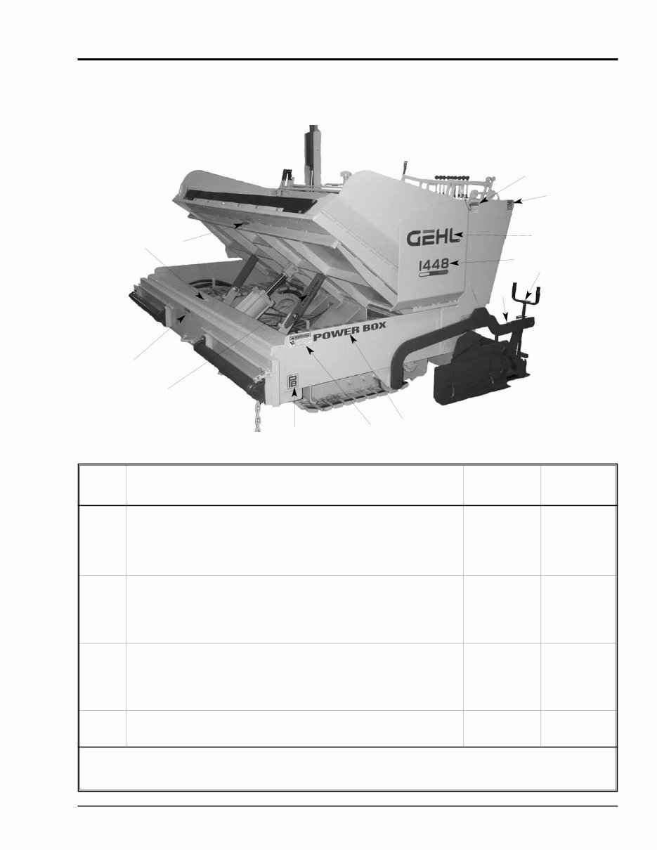
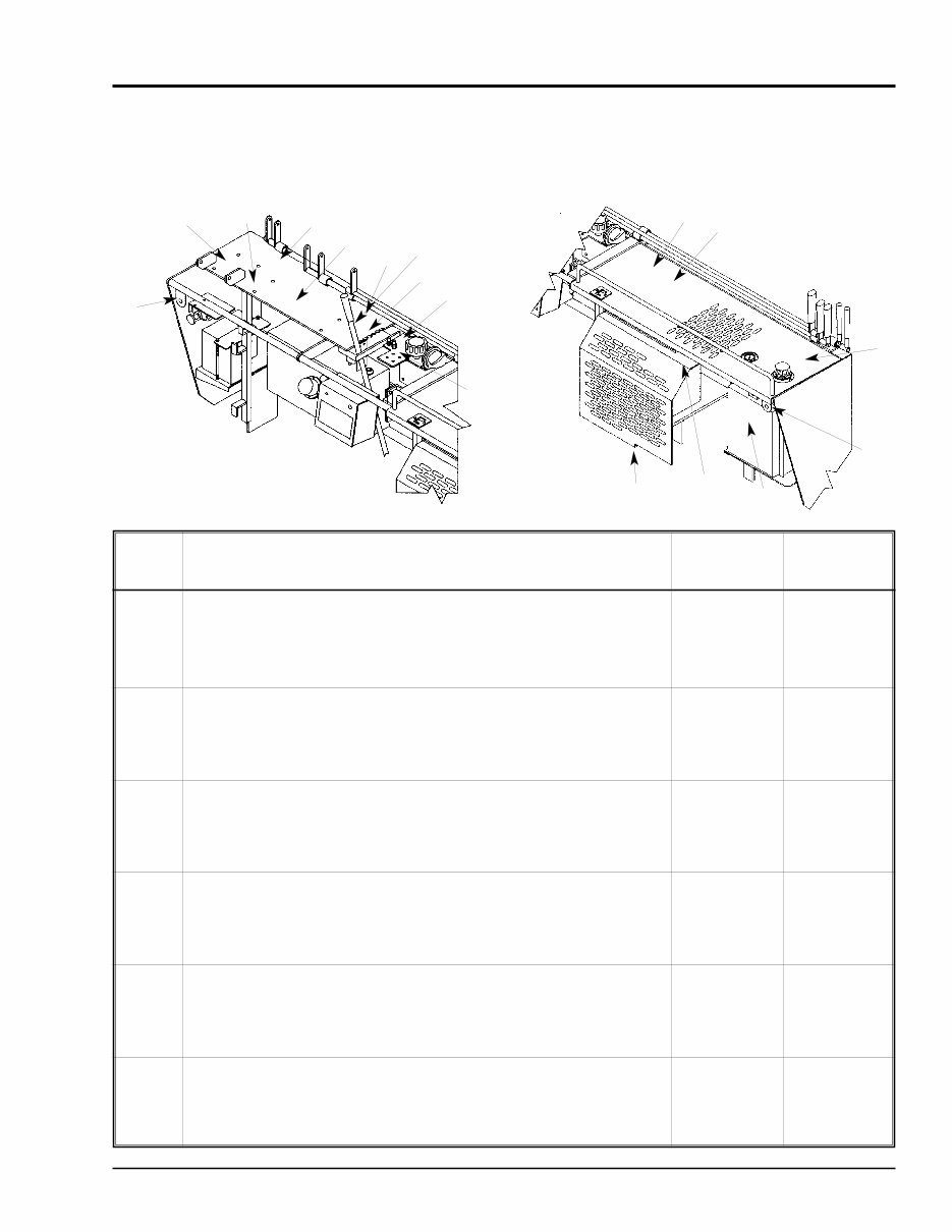
PRINTED IN U.S.A. 5 913209/BP0107 1438/1448 Power Box Decals Lower Frame, Hopper and Screed Areas 1 11 10 1 9 8 1 7 5 6 4 3 2 REF. DESCRIPTION 1438 1448 NO. 01 WARNING - Pinch Point (each side) L65927 L65927 02 Made in USA 137654 137654 03 a GEHL Lettering (each side) L82282 L82282 03 b GEHL Lettering (each side) 137551 04 a Model Number - 1438 or 1448 (each side) P470322 P470852 04 b Model Number - 1448 (each side) 101483 05 Up/Down Screed ((each pullarm) P214000 P214000 06 0-6 Thickness Indicator (each pullarm) P201400 P201400 07 a PowerBox Lettering (each side) P204030 P204030 07 b PowerBox Lettering (each side) 101481 08 a PB Logo, 5” (each side) P470323 P470323 08 b PB Logo, 5” (each side) 101482 09 Floor Safety Prop (each safety prop) P210200 P210200 10 Hydraulic Fluid (1 ea.) 137632 137632 a All 1438’s. 1448’s thru S/N 17637. b 1448 S/N 17638 and up.
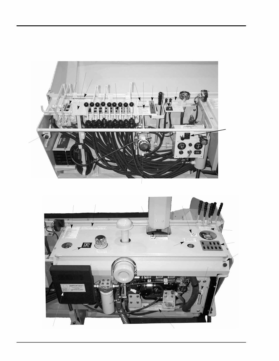
913209/BP0107 6 PRINTED IN U.S.A. Decals 1438/1448 Power Box Backwall and Console Area (1448 Locations) 23 6 14 22 21 20 1 19 18 16 17 15 13 12 11 10 8 9 7 5 4 3 2 1
This is a comprehensive Parts Manual for the Gehl 1438 1448 Power Box Self-Propelled Paver. The manual features easy-to-read text sections with high-quality diagrams and instructions, making it suitable for both do-it-yourself enthusiasts and experienced mechanics. It includes step-by-step instructions and detailed exploded pictures and diagrams to assist in completing the required job correctly and efficiently.
The Gehl 1438 1448 Power Box Self-Propelled Paver Parts Manual covers every single detail of the machine and provides instructions based on the complete disassembly of the machine. This manual is an inexpensive way to ensure the proper functioning of your vehicle.
Serial Numbers: 18100 and Before
Form No.: 913209 Rev B (Replaces 907875)
Manual Covers:
Introduction
Decals Section
Chassis Section
Drive Train
Hydraulic Assemblies Section
Hydraulic Components Section
Miscellaneous Section
And More......
File Format: PDF
Compatibility: All Versions of Windows & Mac
Language: English
Requirements: Adobe Reader & Win
No waiting, all pages are printable. The Gehl 1438 1448 Power Box Self-Propelled Paver Parts Manual saves you money on postage and packaging. It is great to have.
Reviews
Q&A
Recently Viewed
5,521,897Happy Clients
2,594,462eManuals
1,120,453Trusted Sellers
15Years in Business
Price:
Actual Price:
Gehl 1438 1448 Power Box Self-Propelled Paver Parts Manual (Serial Numbers 18100 and Before)

")