2007 W62 Chassis WSM0419
SECTION
8
PAGE
1
2007 W62 Chassis
Electrical Systems
© 2006 Workhorse Custom Chassis — All Rights Reserved
WORKHORSE CUSTOM CHASSIS
Service Manual
2007
ELECTRICAL SYSTEMS
WORKHORSE CUSTOM CHASSIS
Service Manual
2007 W62 Chassis WSM0419
SECTION
8
PAGE
2 Electrical Systems
2007 W62 Chassis
TOC
© 2006 Workhorse Custom Chassis — All Rights Reserved
TABLE OF CONTENTS
DESCRIPTION AND OPERATION .................................... 5
Diagnostic Link Connector Description ........................ 5
16-Pin DLC .................................................................. 5
9-Pin DLC .................................................................... 5
Lighting Systems Description ...................................... 5
Headlamps .................................................................. 5
Daytime Running Lamps ............................................. 6
Flash-To-Pass .............................................................. 6
Park Lamps ................................................................. 6
Turn Lamps ................................................................. 6
Hazard Lamps ............................................................. 6
Stoplamps .................................................................... 6
Backup Lamps ............................................................. 6
Windshield Wiper/Washer System Description ........... 6
LOW or MIST Position ................................................. 7
HIGH Position .............................................................. 7
DELAY Operation ........................................................ 7
Washer Pump .............................................................. 7
Horns Description ........................................................ 8
Cruise Control System Description .............................. 8
Wiring Systems Description ......................................... 8
Schematic Information ................................................. 8
CIRCUIT PROTECTION ........................................... 11
Fuses ......................................................................... 11
Circuit Breakers ......................................................... 12
Fusible Links .............................................................. 13
Wiring Repairs ........................................................... 14
Repairing Damaged Wire Insulation .......................... 14
Wiring Harness Replacement .................................... 14
Heated Oxygen Sensor (HO2S) Wiring Repairs ....... 14
Diagnosis Using The Wiring Schematics ................... 14
Schematic Icons ........................................................ 14
Connector Reference Zone Numbers ........................ 14
Underhood Fuse Panel .............................................. 15
Instrument Cluster Description and Operation .......... 15
Test at Turn On .......................................................... 22
Access to Diagnostic Menus and Menu Operation .... 22
Menu Operation ......................................................... 22
Adjusting Display Contrast ........................................ 23
Restore Default .......................................................... 23
Gauge Backlight ........................................................ 24
Software version ........................................................ 24
Part Number .............................................................. 24
Engine hours ............................................................. 24
Max Engine RPM ....................................................... 24
Max Vehicle Speed .................................................... 24
Engine Oil Life Remaining ......................................... 25
DIAGNOSTIC INFORMATION AND PROCEDURES ..... 26
General Electrical Diagnosis Procedures .................. 26
Basic Knowledge Required ....................................... 26
Electromotive Force ................................................... 26
Voltage ....................................................................... 26
Resistance ................................................................. 27
Ohms ......................................................................... 27
Tips for Using an Ohmmeter ..................................... 27
Ohm’s Law ................................................................. 28
Electrical Current ....................................................... 30
Amperage .................................................................. 30
Ammeter .................................................................... 30
The Diagnostic Process ............................................. 31
General Electrical Diagnosis ..................................... 33
Troubleshooting with a Digital Multimeter (DMM) ...... 33
Measuring Voltage ..................................................... 34
Measuring Voltage Drop ............................................ 35
Measuring Frequency ................................................ 36
TOC
WORKHORSE CUSTOM CHASSIS
Service Manual
2007 W62 Chassis WSM0419
SECTION
8
PAGE
3 Electrical Systems
2007 W62 Chassis
TOC
© 2006 Workhorse Custom Chassis — All Rights Reserved
Testing for Continuity ................................................. 36
Testing for Short to Ground ....................................... 37
Testing for a Short to Voltage .................................... 38
Troubleshooting with a Short Finder .......................... 39
Troubleshooting with a Test Lamp ............................. 39
Probing Electrical Connectors ................................... 39
Using Connector Test Adapters ................................. 40
Using Fused Jumper Wires ....................................... 40
Using Connector Test Adapters ................................. 40
Intermittents and Poor Connections .......................... 41
Testing for Intermittent Conditions and Poor
Connections ............................................................ 41
Testing for Proper Terminal Contact .......................... 42
Testing for Proper Terminal Contact in Bussed
Electrical Centers (BEC) ......................................... 42
Flat Wire (Dock and Lock) Connectors ...................... 43
Control Module/Component Voltage and Grounds .... 43
Temperature Sensitivity ............................................. 44
Electromagnetic Interference (EMI) and Electrical
Noise ...................................................................... 44
Inducing Intermittent Fault Conditions ....................... 45
Low Temperature Conditions ..................................... 46
Duplicating Failure Conditions ................................... 47
Testing for Electrical Intermittents .............................. 47
Diagnostic Link Connector Diagnostics ..................... 48
Data Link Communications System Check .............. 48
Scan Tool Does Not Communicate with
Components ............................................................ 49
Scan Tool Does Not Communicate with PCM ........... 51
Scan Tool Does Not Communicate with TCM ........... 52
Lighting Systems ....................................................... 55
Courtesy or Dome Lamps Always On ........................ 55
Courtesy or Dome Lamps Inoperative ....................... 56
Instrument Panel Lighting Issues .............................. 58
Windshield Wiper/Washer Diagnosis ........................ 59
Washer Always On .................................................... 59
Washers Inoperative .................................................. 60
Wipers Inoperative – All Modes ................................. 62
Wipers Delay Mode Inoperative ................................ 63
Wipers High Mode Inoperative .................................. 64
Wipers Low or Mist Modes Inoperative ..................... 65
Cruise Control Diagnostics ........................................ 67
Cruise Control System Check ................................... 67
Cruise Control Does Not Set or Accelerate ............... 68
Horns ......................................................................... 72
Horns Always On ....................................................... 72
Horns Inoperative ...................................................... 73
Adjustable Pedals Diagnosis ..................................... 76
DTC U1001-U1254 .................................................... 78
DTC U1300, U1301, or U1305 .................................. 82
Instrument Cluster Diagnostic Information ................ 83
Cluster Diagnostic ..................................................... 83
Gauge Test ................................................................ 83
Warning Lamps Test .................................................. 84
LCD Test .................................................................... 84
Backlighting Test ........................................................ 85
Speaker Test .............................................................. 85
Switch Inputs ............................................................. 86
Analog Inputs ............................................................. 86
Frequency Inputs ....................................................... 87
Troubleshooting the Instrument Cluster .................... 87
Gauges ...................................................................... 87
Warning lights ............................................................ 89
Backlighting ............................................................... 91
Misc . .......................................................................... 92
WORKHORSE CUSTOM CHASSIS
Service Manual
2007 W62 Chassis WSM0419
SECTION
8
PAGE
4 Electrical Systems
2007 W62 Chassis
TOC
© 2006 Workhorse Custom Chassis — All Rights Reserved
REPAIR INSTRUCTIONS ................................................ 98
Wiring Repairs ........................................................... 98
Repairing Damaged Wire Insulation .......................... 98
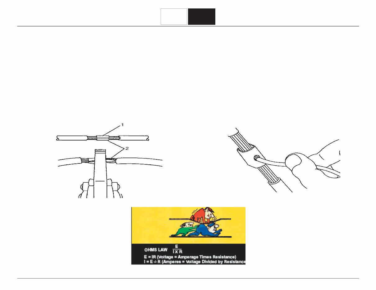
Splicing Copper Wire ................................................. 98
Splicing Twisted Pair Wiring .................................... 102
HO2S Wiring Repairs .............................................. 103
Headlamp Switch Replacement .............................. 103
WORKHORSE CUSTOM CHASSIS
Service Manual
2007 W62 Chassis WSM0419
SECTION
8
PAGE
5 Electrical Systems
2007 W62 Chassis
TOC
© 2006 Workhorse Custom Chassis — All Rights Reserved
9-Pin DLC
The 9-pin Diagnostic Link Connector (DLC) allows the
technician to access the Allison Transmission Control
Module (TCM) and/or the Electronic Control Unit (ECU)
for the WABCO anti-lock brake system (ABS).
7 of the pins in the connector are used. The pin
assignments are:
• Pin A – chassis ground via ground terminal 12
• Pin B – Battery voltage to DLC
• Pin C – J1939 Hi
• Pin D – J1939 Lo
• Pin E – J1939 Shield (ground)
• Pin F – J1587 Hi
• Pin G – J1587 Lo.
LIGHTING SYSTEMS DESCRIPTION
Headlamps
The headlamps will turn on when the headlamp switch
is placed in the ON position. When the low beam
headlamps are on, the headlamps can be switched to
the high beams by pulling the headlamp dimmer switch
toward the driver until it clicks. When the headlamp
dimmer switch is again pulled until it clicks, the
headlamps will then switch to the low beams from the
high beams.
DESCRIPTION AND OPERATION
DIAGNOSTIC LINK CONNECTOR DESCRIPTION
All 2007 Model Year (2007MY) W62 chassis are
equipped with two Diagnostic Link Connectors (DLC).
The 16-pin DLC is used to connect a scan tool or
laptop for the purpose of performing engine control
system diagnostics. The 9-pin “Deutsch” DLC is used
to connect a scan tool or laptop for the purpose of
performing transmission and/or anti-lock brake system
(ABS) diagnostics.
16-Pin DLC
The 16-pin DLC is used to connect a scan tool for
the purpose of performing engine control system
diagnostics. Establishing communication allows the
operator to monitor the systems for diagnostic purposes.
Only 4 of the 16 pins are used. The pin assignments
are:
• Pin 2 – Class 2 Serial Data link to instrument cluster/
PCM/ECM
• Pin 4 – Ground terminal 12
• Pin 5 – Ground terminal 37
• Pin 16 – Battery voltage feed to DLC.
WORKHORSE CUSTOM CHASSIS
Service Manual
2007 W62 Chassis WSM0419
SECTION
8
PAGE
6 Electrical Systems
2007 W62 Chassis
TOC
© 2006 Workhorse Custom Chassis — All Rights Reserved
Daytime Running Lamps
The optional Daytime Running Lamps (DRL) illuminate
the high beam headlamps at a reduced intensity. The
DRL will operate when the ignition switch is in the RUN
or START position and the gear selector lever is out
of the PARK position. DRL is a programmable feature
for vehicles sold in the United States. Turning on the
headlamps will disable the DRL system.
Flash-To-Pass
When the headlamp dimmer switch is pulled toward
driver, but does not click, the high beam headlamps will
light for as long as the switch is held. This will occur in
any headlamp state (off, DRL, low beams).
Park Lamps
The park lamps will turn on when the headlamp switch is
placed in the PARK or ON position.
Turn Lamps
The turn lamps can only be activated with the ignition
switch in RUN or START. When the turn signal switch is
placed in a position to indicate a left turn or a right turn,
the respective turn lamps will flash. The respective turn
indicator will flash on the Instrument Panel Cluster (IPC).
Hazard Lamps
When the hazard switch is pressed, all turn lamps will
flash. Both turn indicators will flash on the Instrument
Panel Cluster (IPC).
Stoplamps
When the brake pedal is pressed, all stoplamps
illuminate.
Backup Lamps
When the ignition switch is in RUN and the gear selector
lever is in REVERSE, the backup lamps light. Instrument
Cluster Dimming The instrument cluster lamps light
when the park lamps are on. The brightness of the
instrument cluster lamps is controlled by the instrument
cluster dimmer switch located on the instrument panel.
WINDSHIELD WIPER/WASHER SYSTEM
DESCRIPTION
Voltage is supplied to the wiper motor via the WIPER
fuse when the ignition switch is in the ACC or RUN
position. Different speeds and functions of the wiper
motor are achieved by completing different ground paths
through the wiper pulse control module. The windshield
wiper relay feed coil is used to keep the wiper motor
running. When the windshield wiper relay feed coil circuit
is not grounded, the motor will not turn. Closing the
various contacts in the wiper/washer switch will provide
ground for this circuit and allow the motor to turn.
WORKHORSE CUSTOM CHASSIS
Service Manual
2007 W62 Chassis WSM0419
SECTION
8
PAGE
7 Electrical Systems
2007 W62 Chassis
TOC
© 2006 Workhorse Custom Chassis — All Rights Reserved
LOW or MIST Position
With the wiper/washer switch in the LOW or MIST
position:
• Power is supplied to the Pulse Wiper Control Module via
circuit 143 (YEL)
• Ground is provided to the Pulse Wiper Control Module
via circuit 150 (BLK)
• Low signal is supplied by the Pulse Wiper Control
Module to the body builder wiper system via circuit 97
(LT BLU)
• Coil feed signal is supplied by the Pulse Wiper Control
Module to the body builder wiper system via circuit 91
(GRA)
• Multifunction switch signal is provided to the Pulse Wiper
Control Module via circuit 112 (GRA)
HIGH Position
With the wiper/washer switch in the HIGH position:
• Power is supplied to the Pulse Wiper Control Module via
circuit 143 (YEL)
• Ground is provided to the Pulse Wiper Control Module
via circuit 150 (BLK)
• Low signal is supplied by the Pulse Wiper Control
Module to the body builder wiper system via circuit 97
(LT BLU)
• Coil feed signal is supplied by the Pulse Wiper Control
Module to the body builder wiper system via circuit 91
(GRA)
• Multifunction switch signal is provided to the Pulse Wiper
Control Module via circuit 112 (GRA)
• High signal is supplied by the multifunction switch to the
body builder wiper system via circuit 92 (PPL).
DELAY Operation
With the multifunction switch in one of the delay
positions:
• Power is supplied to the Pulse Wiper Control Module via
circuit 143 (YEL)
• Ground is provided to the Pulse Wiper Control Module
via circuit 150 (BLK)
• Coil feed signal is supplied by the Pulse Wiper Control
Module to the body builder wiper system via circuit 91
(GRA)
• Multifunction switch signal is provided to the Pulse Wiper
Control Module via circuit 112 (GRA).
Washer Pump
When the contacts of the wash switch in the wiper
washer switch close:
• Power is supplied to the Pulse Wiper Control Module via
circuit 143 (YEL)
• Ground is provided to the Pulse Wiper Control Module
via circuit 150 (BLK)
• Low signal is supplied by the Pulse Wiper Control
Module to the body builder wiper system via circuit 97
(LT BLU)
WORKHORSE CUSTOM CHASSIS
Service Manual
2007 W62 Chassis WSM0419
SECTION
8
PAGE
8 Electrical Systems
2007 W62 Chassis
TOC
© 2006 Workhorse Custom Chassis — All Rights Reserved
Depressing the SET and the R/A switches
simultaneously will cancel the cruise control operation.
Canceling the cruise control operation will not cancel the
speed memory.
WIRING SYSTEMS DESCRIPTION
Schematic Information
Where to Find Schematics
The electrical schematics for the 2007 W-Series are
not included in the service manual itself. Instead, the
schematics reside on the Workhorse Dealers website
(www.dealers.workhorse.com).
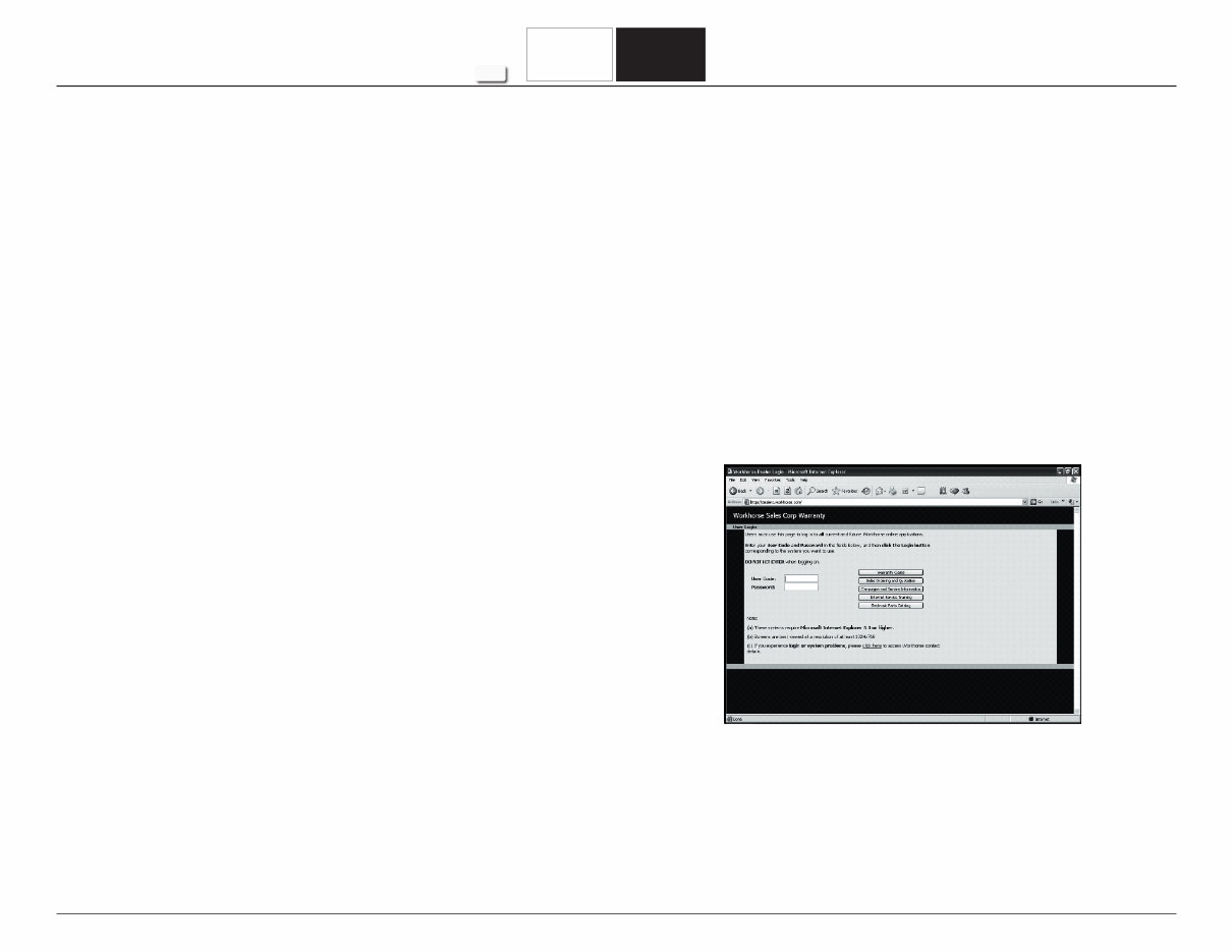
Using the dealer’s user code and password, the
technician can access the engineering drawings. Type
the user code into the User Code field and the password
into the Password field. DO NOT press the enter key.
Use the mouse, and left click on the Campaigns and
Service Information box in the center of the screen.
• Coil feed signal is supplied by the Pulse Wiper Control
Module to the body builder wiper system via circuit 91
(GRA)
• Multifunction switch signal is provided to the Pulse Wiper
Control Module via circuit 112 (GRA)
• Output signal is supplied by the Pulse Wiper Control
Module to the body builder wiper/washer system via
circuit 94 (PNK).
HORNS DESCRIPTION
The HORN fuse applies voltage at all times to the horn
relay. When the horn button is depressed, the contacts
for the horn switch close to ground. The horn relay
energizes and the contacts for the horn relay switch
close. This supplies voltage directly to the right and left
horns. Both horns are grounded through ground terminal
19.
CRUISE CONTROL SYSTEM DESCRIPTION
The cruise control system maintains the desired vehicle
speed under normal driving conditions. The cruise
control system has the following capabilities:
CRUISE
RESUME SPEED
ACCELERATE
COAST
WORKHORSE CUSTOM CHASSIS
Service Manual
2007 W62 Chassis WSM0419
SECTION
8
PAGE
9 Electrical Systems
2007 W62 Chassis
TOC
© 2006 Workhorse Custom Chassis — All Rights Reserved
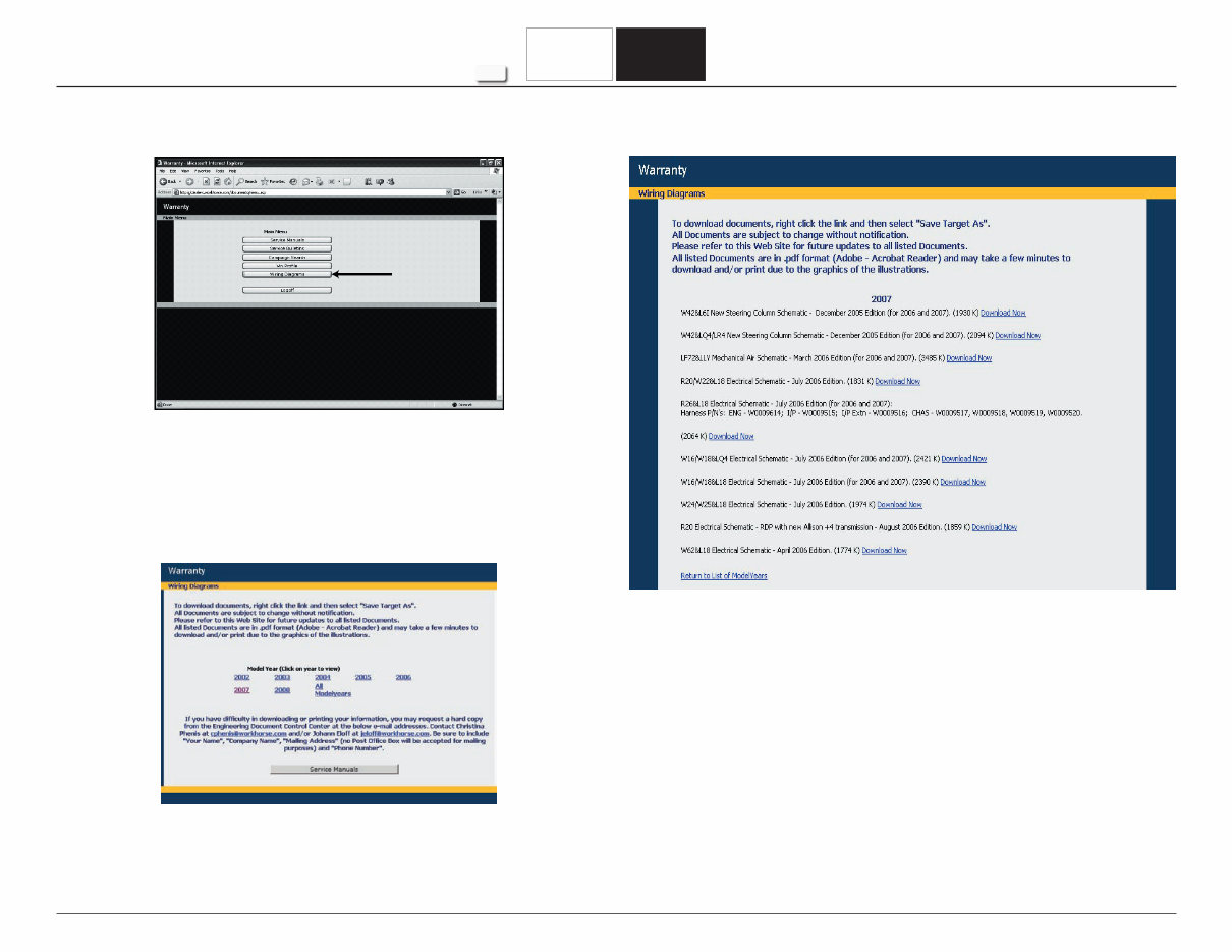
After selecting the 2007MY link, a page will be displayed
that shows all of the drawings available for the 2007MY.
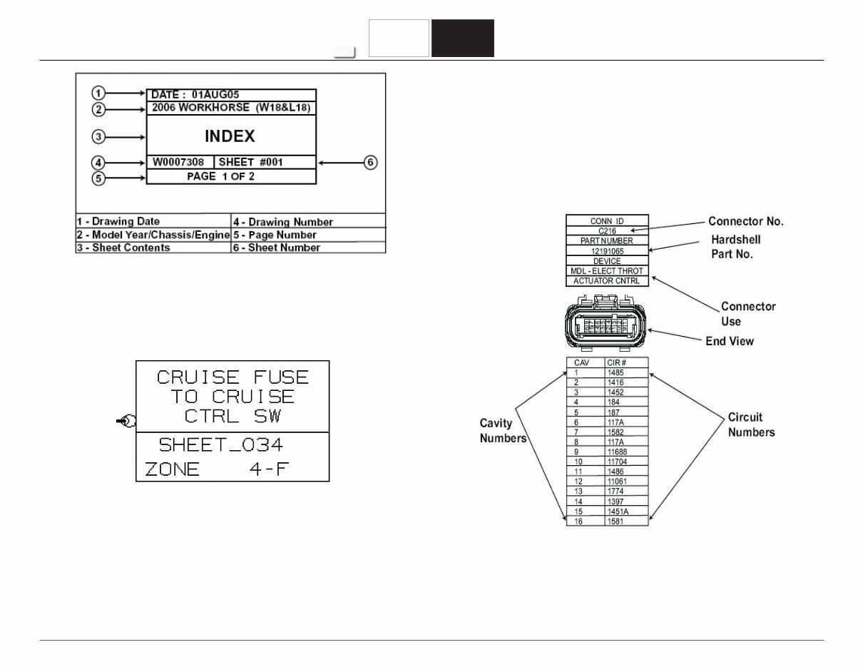
How to Use Schematics
In the lower right corner of each page of the wiring
diagram is a box containing information on the page’s
contents.
Note: As with other engineering documents a “sheet”
contains information specific to a system or
subsystem. Sheets may have more than one
page.
When the main menu screen appears, click on the
Wiring Diagrams button.
After clicking on the Wiring Diagrams button, the
technician will be presented with a screen showing with
several model year links. Clicking on the 2007 link, will
result in the page with the links for all of the electrical
schematics for the 2007 MY being displayed.
WORKHORSE CUSTOM CHASSIS
Service Manual
2007 W62 Chassis WSM0419
SECTION
8
PAGE
10 Electrical Systems
2007 W62 Chassis
TOC
© 2006 Workhorse Custom Chassis — All Rights Reserved
Navigation Box
When a circuit continues elsewhere on the same page
or on another page, a Navigation Box is shown to help
you locate the continuation of the circuit.
The top portion of the box gives you the details of
the circuit. Below the line, the point where the circuit
continues is shown along with the grid locator. Use the
grid locator in the same way that a road map is used to
pinpoint the location.
Connector End Views
Connector End Views show the cavity or terminal
locations for all the related connectors shown in the
system schematics. The drawings show the connector
face as seen after the harness connector has been
disconnected from a component or mating connector.
Unused cavities are left blank in the table.
You're Reading a Preview
What's Included?
Lifetime Access
Access Contents & Bookmarks
Print one or all pages of your manual