TP 39179202 XC90 2011 3 Vehicles with SRS (Airbag)/SIPS bag/IC (Inflatable curtain) 2 Explanations .................................................................. 6 Abbreviations ................................................................. 6 How to use the wiring diagrams 1:2............................... 7 Electrical distribution 1:2 ................................................ 9 Fuses Engine compartment 11A/1-5 ....................................... 11 Engine compartment 11B/1-11 ..................................... 12 Engine compartment 11B/12-14 ................................... 13 Engine compartment 11B/15 ........................................ 14 Engine compartment 11B/16-21 ................................... 15 Passenger compartment 11C/1-4 ................................. 16 Passenger compartment 11C/5-7 ................................. 17 Passenger compartment 11C/8-10 ............................... 18 Passenger compartment 11C/11-14............................. 19 Passenger compartment 11O/1-2................................. 20 Cargo compartment 11E/1-7 ........................................ 21 Cargo compartment 11L/1 ............................................ 22 Cargo compartment 11O/6-12 ...................................... 23 Central electronic module (CEM) F1-F11 ..................... 24 Central electronic module (CEM) F15-F34 ................... 25 Rear electronic module (REM) F1-F7 ........................... 26 Rear electronic module (REM) F8-F28 ......................... 27 Rear electronic module (REM) F29-F38 ....................... 28 Relays Ignition switch and relays............................................. 29 Engine compartment FMA1 - FST3 ............................. 30 Cargo compartment R1-R3.......................................... 31 Other relays ................................................................. 32 Ground connections Overview...................................................................... 33 31/1 - 31/44 ................................................................. 34 31/46 - 31/67 ............................................................... 35 31/70 - 31/83 ............................................................... 36 31/84 - 31/88 ............................................................... 37 31/89 - 31/93................................................................ 38 31/94 - 31/102.............................................................. 39 31/120 - 31/121............................................................ 40 Control modules Overview locations ....................................................... 41 Overview designations ................................................. 42 Central electronic module (CEM) 1:2 ........................... 43 Rear Electronic Module (REM) 1:2 .............................. 45 Data communication high speed CAN ......................... 47 Data communication Low speed CAN ......................... 48 Data communication, LIN 1:2....................................... 49 Data communication MOST......................................... 51 Group 23 Fuel system Engine management system, Diesel 1:3 ..................... 52 Engine management system, 5-Cyl. Turbo 1:2............ 55 Engine management system, 6-Cyl. 1:2 ...................... 57 Engine management system, 8-Cyl. 1:2 ...................... 59 Emission control 5-Cyl. Turbo ...................................... 61 Emission control 6-Cyl. ............................................... 62 Emission control 8-Cyl. ................................................ 63 Group 26 Cooling system Cooling fan 5-Cyl. ........................................................ 64 Cooling fan, Diesel, 6-Cyl. & 8-Cyl............................... 65 Group 27 Engine controls Cruise control 5-Cyl. .................................................... 66 Cruise control, Diesel, 6-Cyl. & 8-Cyl............................ 67 Group 32 Alternator and voltage regulator Power supply ............................................................... 68 Group 33 Starting system Starting system 5-Cyl................................................... 69 Starting system, Diesel, 6-Cyl. & 8-Cyl. ....................... 70 Table of Contents 1:3
TP 39179202 XC90 2011 4 Group 35 Lighting High and low beam/(Dual-Xenon) & Daytime Running Lights ........................................................................ 71 Active headlights (ABL) ............................................... 72 Fog lights ..................................................................... 73 Brake lights .................................................................. 74 Reversing lights ........................................................... 75 Follow-me-home lighting.............................................. 76 Running/parking light, tail lights & license plate lighting 77 Interior lighting ............................................................. 78 Beam length adjustment .............................................. 79 Auxiliary lights .............................................................. 80 Group 36 Additional electrical equipment Rain sensor.................................................................. 81 Direction indicator and hazard warning flashers .......... 82 Wiper/Washer Windshield ........................................... 83 High pressure headlight washer .................................. 84 Wiper/Washer Rear window ........................................ 85 Horn ........................................................................ 86 Immobilizer .................................................................. 87 Anti-theft alarm ............................................................ 88 Parking assistance....................................................... 89 Alcohol lock.................................................................. 90 Accessory Electronic Module (AEM) 1:2 ..................... 91 Group 37 Wiring and fuses Diagnostics system...................................................... 93 Outlet 12 V................................................................... 94 Cable harness towbar/tow hitch 4/7 pin ....................... 95 Cable harness towbar/tow hitch 7-pin.......................... 96 Cable harness towbar/tow hitch 13-pin........................ 97 Accessory USB unit (AUU) .......................................... 98 Group 38 Instruments Seat belt reminder ....................................................... 99 Driver information module 5-Cyl. ............................... 100 Driver information module Diesel ............................... 101 Driver information module 6-Cyl. ............................... 102 Driver information module 8-Cyl. ............................... 103 Group 39 Other Audio with external amplifier ...................................... 104 Audio with internal amplifier ....................................... 105 Navigation system, portable....................................... 106 Road Traffic Information (RTI) ................................... 107 Satellite radio ............................................................. 108 Rear seat entertainment ............................................ 109 Rear seat entertainment, accessory .......................... 110 Infotainment ............................................................... 111 Rear set entertainment roof mounted ........................ 112 Parking camera.......................................................... 113 Parking camera & AEM.............................................. 114 Bluetooth handsfree, external amplifier ..................... 115 Bluetooth handsfree, internal amplifier ...................... 116 Bluetooth handsfree with AEM, internal amplifier, LHD .... 117 Bluetooth handsfree with AEM, internal amplifier, RHD ... 118 Bluetooth handsfree with AEM, external amplifier, LHD ... 119 Bluetooth handsfree with AEM, external amplifier, RHD .. 120 Group 43 Transmission Automatic transmission AW51 AWD.......................... 121 Automatic transmission TF-80SC AWD 8-Cyl. .......... 122 Automatic transmission TF-80SC/TF-80SC AWD 6-Cyl. & Diesel ...................................................................... 123 Geartronic AW51 AWD .............................................. 124 Shift lock AW51 AWD & Manual ................................ 125 Differential Electronic Module (DEM) ......................... 126 Table of Contents 2:3
TP 39179202 XC90 2011 5 Group 59 Brake system Brake control system ................................................. 127 Group 64 Steering Speed dependent power steering .............................. 128 Group 83 Doors and openings Central locking ........................................................... 129 Power windows .......................................................... 130 Power sunroof............................................................ 131 Group 84 Exterior decorative elements, etc. Power door mirrors .................................................... 132 Blind spot information system.................................... 133 Heated door mirrors ................................................... 134 Heated rear window................................................... 135 Group 85 Interior equipment Power driver’s seat .................................................... 136 Power passenger seat ............................................... 137 Heated seats.............................................................. 138 Massage seats with ventilation .................................. 139 Heated seats second row of seats............................. 140 Group 87 Climate control system Climate control system, 5-Cyl. 1:2 ............................. 141 Climate control system, Diesel, 6-Cyl. & 8-Cyl. 1:2 ... 143 Climate control system, rear ...................................... 145 Parking heater, auxiliary heater ................................. 146 Parking heater, remote start ...................................... 147 Relay, electric engine heater ..................................... 148 Group 88 Internal equipment Remote control garage opening................................. 149 Supplemental restraint system................................... 150 Connectors................................................ 151 Branching points ..................................... 177 Cable harness routine in vehicle Engine harness Gasoline 5-Cyl. ................................. 187 Engine harness Gasoline 6-Cyl. ................................. 188 Engine harness 8-Cyl.................................................. 188 Diesel engine harness ................................................ 189 Engine compartment harness LHD............................. 190 Engine compartment harness RHD ............................ 191 Harness passenger compartment LHD....................... 192 Harness passenger compartment RHD ...................... 193 Cargo compartment harness ...................................... 194 Roof harness .............................................................. 195 Tailgate harness ......................................................... 195 Harness doors ............................................................ 196 Executive harnesses ................................................... 197 Component illustrations .......................... 198 Index 1:3 .................................................... 251 List of components 1:7 ............................ 254 Table of Contents 3:3
TP 39179202 XC90 2011 6 Explanations Abbreviations Groups Group 23 = Fuel system Group 26 = Cooling system Group 27 = Engine controls Group 32 = Alternator and voltage regulator Group 33 = Starting system Group 35 = Lighting Group 36 = Additional electrical equipment Group 37 = Wiring and fuses Group 38 = Instruments Group 39 = Other Group 43 = Transmission Group 59 = Brake system Group 64 = Steering Group 76 = Shock absorbers Group 83 = Doors and openings Group 84 = Exterior decorative elements, etc. Group 85 = Interior equipment Group 87 = Climate control system Group 88 = Internal equipment Ignition switch symbols X = Accessories (audio position) S = Powered upon insertion of key 15 = Contact remains connected during start 15l = Contact is broken while starting 30 = Constant power from the battery 50 = Start Countries/Markets A = Austria AUS = Australia B = Belgium CDN = Canada CH = Switzerland D = Germany DK = Denmark E = Spain EU/OS = Markets outside USA and Canada FIN = Finland GB = Great Britain ISR = Israel J = Japan KOR = Korea N = Norway NL = Netherlands S = Sweden USA = United States of America WEU = Western Europe Other ABL = Active Dual Xenon headlights ACC = Accessories Ag = Silver plated Au = Gold plated AUDIO = Audio system AUTO = Automatic transmission BLIS = Blind spot information system CEM = Central Electronic Module DIESEL = D5244 T4/T5/T6/T7 DRL = Daytime Running Lights DSTC = Dynamic Stability Traction Control Du-X = Dual Xenon ECC = Electronic climate control system ECPS = Electronic power steering EXC = Exclusive EXT. D = Extended electrical distribution HISPEED = High speed data bus LH = Left-hand side LHD = Left-hand drive LOSPEED = Low speed data bus MAN = Manual transmission MCC = Manual Climate Control PCL = Power Child Lock PETROL = Gasoline REM = Rear Electronic Module RH = Right-hand side RHD = Right-hand drive RTI = Road Traffic Information SRS = Airbag T = Turbocharged engine W/O = Without 5CYL = 5-cylinder engine 6CYL = 6-cylinder engine 8CYL = 8-cylinder engine Colors BL = Blue BN = Brown GN = Green GR = Gray NL = Natural LBL = Light Blue LGN = Light Green OR = Orange P = Pink R = Red SB = Black VO = Violet W = White Y = Yellow
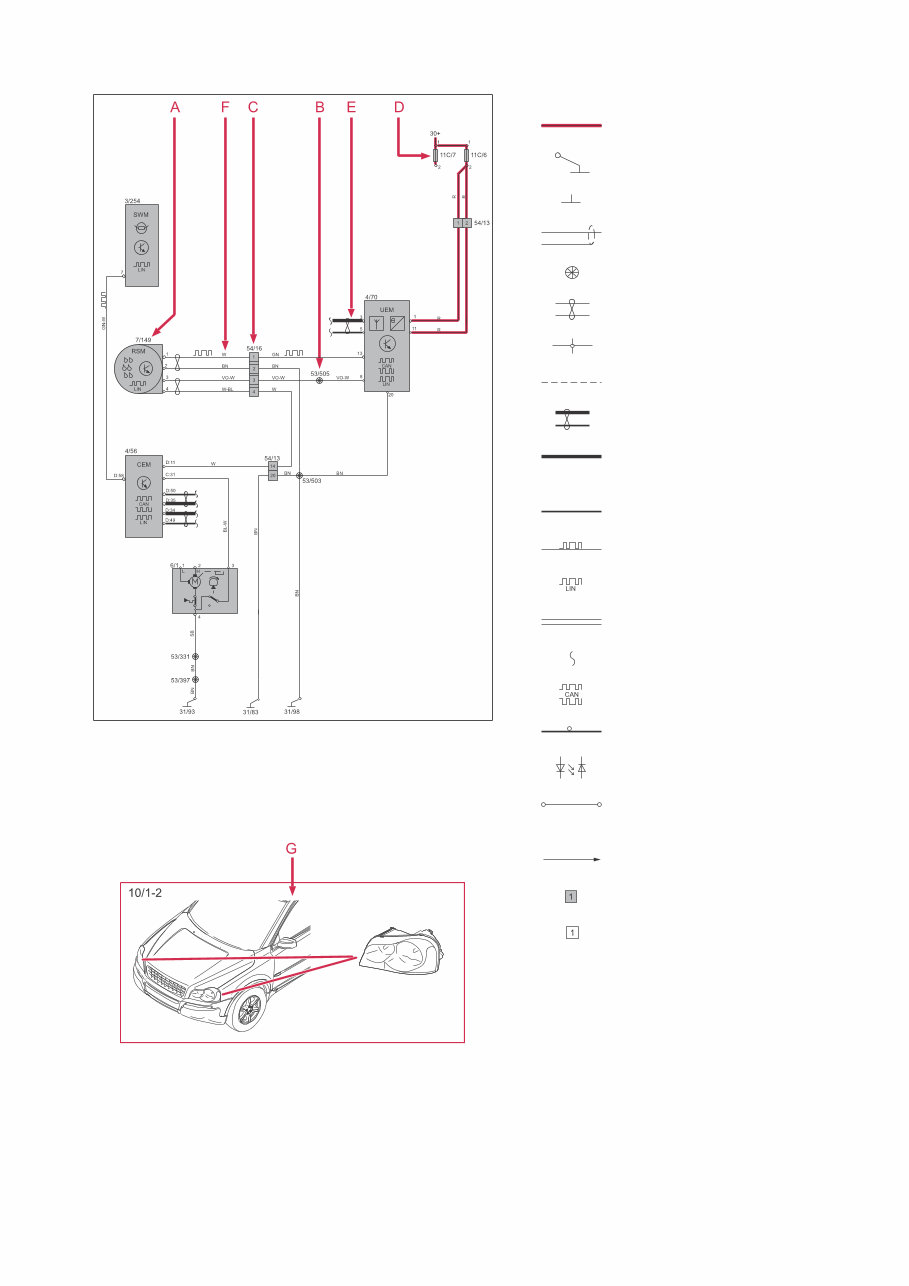
TP 39179202 XC90 2011 7 The descriptions below apply in general to all wiring diagram manuals, although not all sections are necessarily contained in this manual. The systems are shown in non-active status. i.e. with "key removed" and when the doors, hatches and hood are closed. How to use the wiring diagrams 1:2 A. Component designation Every component has a component designation that consists of two parts. The first part is a type number that describes the type of component in question, for example 3/xx. The second part of the designation is a serial num- ber, e.g. x/2. Together, this constitutes a component designation, e.g. 3/2. At the end of the manual is a list of components, where, with the help of the component designation, you can read off the name of the component, for example, 3/2 = light switch. List of type numbers The list shows which type of component that respec- tive type numbers refer to, for example, 3/x = switch, 6/x = electric motor, etc. 1 Battery 2 Relay 3 Switch 4 Control module 5 Driver information module 6 Electric motor 7 Sensor 8 Actuator 9 Heating element 10 Light 11 Fuse 15 Electrical distribution rail/box 16 Audio 17 Service/diagnostics 18 Contact reel 19 Meter 20 Ignition component/shunt 26 Converter 27 Optics 31 Ground connection 53 Branching point 54 Connector B. Branching points The wiring diagrams contain numbered junction points, e.g. 53/352. This manual contains a section with a list of branch- ing points. This list shows all the components that are connected to each branching point. The location of the branching points is shown in the "Cable harness routing in vehicle" section. C. Connectors Connectors provide a bridge between two cable har- nesses and are described in the "Connectors" sec- tion. D. Electrical distribution Operation of the fuses and relays is shown in the "Electrical distribution" section. E. Data communication Today’s cars are equipped with CAN, LIN & MOST networks that transmit information. Connections to these networks are not shown in their entirety on the respective wiring diagram. Complete information on Data communication can be found in the section entitled "Control modules". F. Abbreviations A number of different abbreviations are used in the manual. These are explained in the section "Abbre- viations". G. Component location There is a section at the end of the manual in which the appearance and location of components is described in numerical order.
TP 39179202 XC90 2011 8 How to use the wiring diagrams 2:2 List of symbols = System voltage = Ground connection via wiring = Ground connection in compo- nent/chassis = Screened wire = Junction point = Twisted cable = Electrical connection = Variant = CAN communication = CAN high data signal (CAN H) = CAN low data signal (CAN L) = LIN communication = LIN communication = DIN cable, coaxial cable, etc. = Data communication = CAN communication = MOST communication = MOST communication = Connection with distribution box = Further connection to... = Connector between cable harnesses = Connector connected in com- ponent
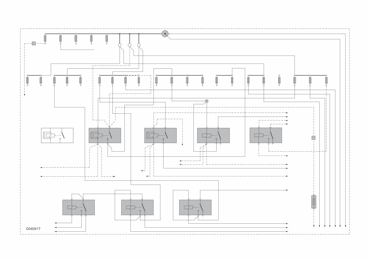
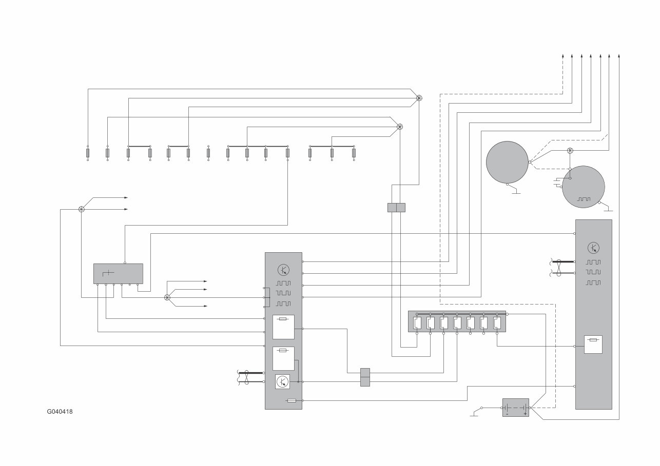
TP 39179202 XC90 2011 10 2 R R R BL-R 4/9B:27/55 53/408 4 3/1 R-SB X 30 5 S 3 7 50 6 15 8 1 15 15I 16/65:1 BL-R 53/443 BL-R 4/9B:28/56 3/157:2 1 11E 6 7 2 4 5 2 2 2 3 2 2 1 F1-38 D:16 B:2 B:24 B:3 B:16 D:15 D:60 4/56 CEM D:8 CAN 1/1 12V + SB SB - 31/53 VO VO BL-R 2 C:13 C:14 REM 54/40D 2 VO VO C:13 D:50 D:35 LIN BL-R Y Y-W C:14 3/157:1 1 E:A E:B A:23 R R R R R Y-R K:1 A:13 ABCDEFG BL BL R-W BL-R R A:29 54/40C 1 2 F3, 5-10, 17-23, 31-32 ,34 F1-2, 1 F29 1, 13-16, 26-30, 33 CAN LIN R R R 11C/11 11C/1 1 1 11C/2 2 2 11C/4 1 1 11C/3 1 11C/5 2 2 2 11C/8 1 11C/6 1 1 11C/7 2 2 2 1 11C/9 1 1 11C/10 2 2 2 11C/13 11C/12 1 1 2 2 53/415 R R R 53/403 11C/14 1 2 R R R DIESEL 53/3009 R R R R R ACM A:1 6/26 B+ 31 G LIN 1 6/25 31 M 30 8CYL 8CYL 4/58 Electrical distribution 2:2 Overview
The Volvo XC90 (2011) wiring diagrams provide a comprehensive set of electrical schematics and diagrams for the Volvo XC90 model of the year 2011. These diagrams are essential for any Volvo XC90 owner or technician who needs to troubleshoot or repair electrical issues in the vehicle.
The wiring diagrams cover all major electrical systems in the Volvo XC90, including the engine management system, ignition system, fuel system, charging system, lighting system, climate control system, audio system, and more. Each diagram provides detailed information on the wiring connections, component locations, and electrical specifications.
Whether you are a DIY enthusiast or a professional mechanic, these wiring diagrams are an invaluable resource for understanding the electrical system of your Volvo XC90 (2011) model. With clear and concise diagrams, you can easily identify electrical faults and perform repairs with confidence.
Models covered in the wiring diagrams:
Volvo XC90 (2011)
With these wiring diagrams, you can ensure the electrical system of your Volvo XC90 (2011) is functioning properly and address any electrical issues with ease.

 wiring diagrams")