GENERAL INFORMATION Administration FAULT-TRACING CAMSHAFT DIAGNOSTICS (CVVT) In addition to electrical checks of the camshaft reset valve, the engine control module (ECM) checks that the position of the camshaft is correct and that the control (deployment and return of the camshaft) is working satisfactorily. The control module uses the signals from the camshaft position sensor and engine speed (RPM) sensor (crankshaft position) for the diagnostics. Checking the camshaft position The control module checks that the 0 position of the camshaft (mechanical rest position) is correct. During certain driving conditions, camshaft control is not active. If this is the case, the control module checks the deviation between the camshaft position (angle position) and the crankshaft position (angle position). The difference is stored in the engine control module (ECM) as an adaption value. A diagnostic trouble code (DTC) is stored in the engine control module (ECM) if the adaptation value becomes too high or low. The deviation of the camshafts from the reference position can be read off. Checking the camshaft control When camshaft control is active, the control module checks that the camshaft moves to the intended position. If the position is not reached, the time the system takes to deploy to the correct camshaft position (the transition time from the actual to the desired camshaft angle) is measured. A diagnostic trouble code (DTC) is stored in the engine control module (ECM) if the camshaft angle does not reach the desired value within a certain time frame. CATALYTIC CONVERTER DIAGNOSTIC For 5 cylinder engines, see CATALYTIC CONVERTER DIAGNOSTICS 5 CYLINDER For 6 cylinder engines, see CATALYTIC CONVERTER DIAGNOSTICS 6 CYLINDER . CATALYTIC CONVERTER DIAGNOSTICS 5 CYLINDER 2008 Volvo XC90 GENERAL INFORMATION Administration
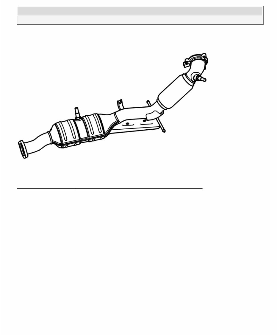
Fig. 1: Identifying Three - Way Catalytic Converter And Heated Oxygen Sensors Courtesy of VOLVO CARS CORPORATION The three-way catalytic converter (TWC) stores oxygen from the exhaust gases and uses it to make toxic gases more environmentally friendly. The catalytic converter is a 3 way catalytic converter in which HC (hydrocarbons) and CO (carbon monoxide) are oxidized and NO x (nitrous oxide) is reduced. As the three-way catalytic converter (TWC) ages its ability to store oxygen drops. This reduces the conversion capacity of the three-way catalytic converter (TWC). To avoid dangerous emissions the engine control module (ECM) checks three-way catalytic converter (TWC) efficiency. In brief, this check is carried out as follows. Two heated oxygen sensors (HO2S) are used to check the three-way catalytic converter (TWC), one upstream of the converter and one in the center of the converter (the rear heated oxygen sensor (HO2S)). The main function of the heated oxygen sensors (HO2S) is to measure the oxygen content in the exhaust gases so that the engine control module (ECM) can maintain the fuel / air mixture at around lambda=1. This mixture allows for optimum catalytic conversion. To determine catalytic converter efficiency the amplitude of the heated oxygen sensor (HO2S) signals is compared (amplitude is a measure of signal oscillation). When efficiency of the catalytic converter is good and the fuel / air mixture is normal, the front probe signal switches between rich and lean while the rear probe signal is steady. If the three-way catalytic converter (TWC) efficiency is poor but the fuel / air mixture is normal, the rear probe signal will also switch between rich and lean. This is because the exhaust gases flow straight through the three-way catalytic converter (TWC) without being acted on. If the amplitude of the rear sensor becomes too great in relation to the amplitude of the front sensor for a number of checks, a diagnostic trouble code (DTC) will be stored for catalytic converter efficiency. 2008 Volvo XC90 GENERAL INFORMATION Administration
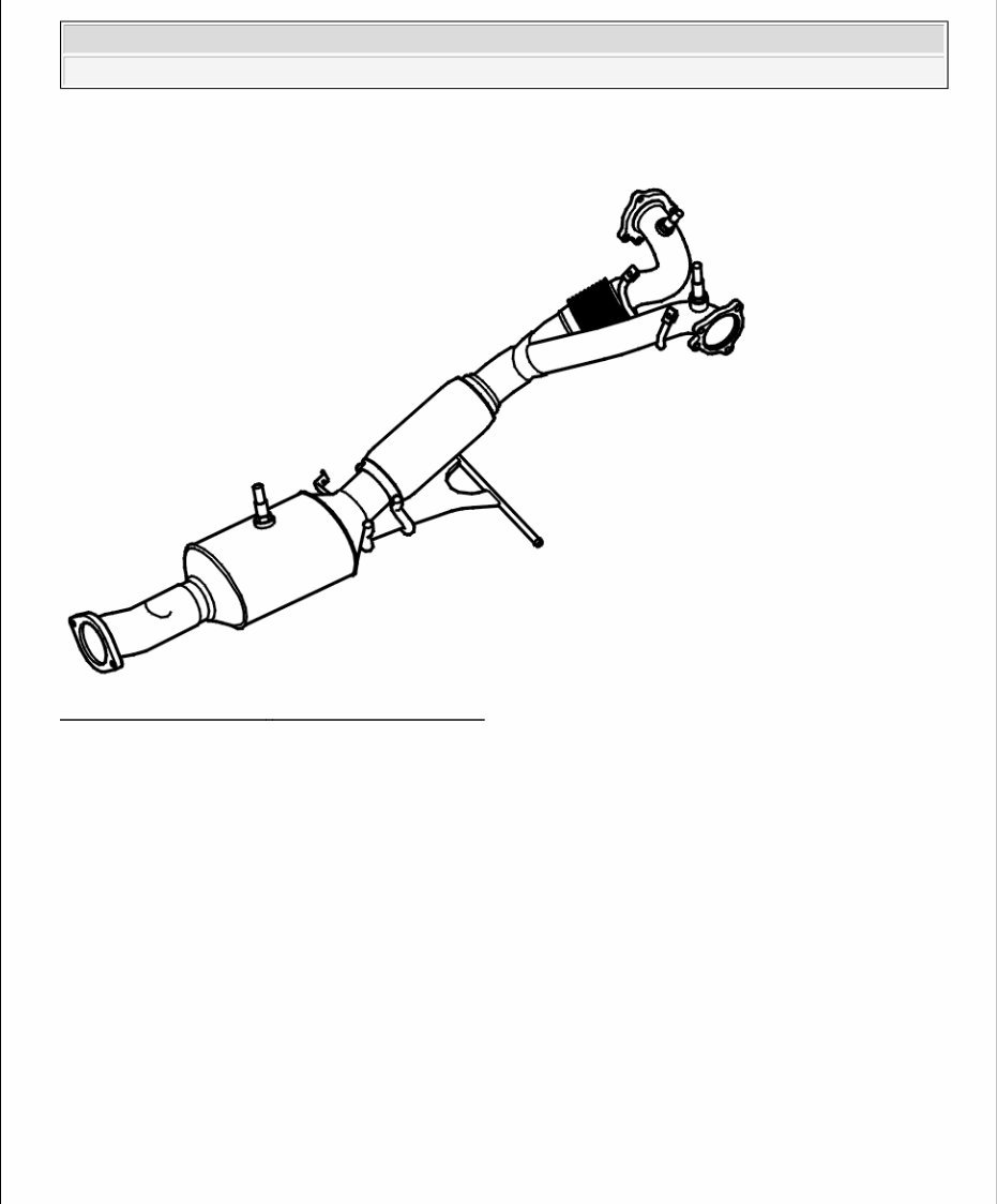
CATALYTIC CONVERTER DIAGNOSTICS 6 CYLINDER Fig. 2: Identifying Three - Way Catalytic Converter Courtesy of VOLVO CARS CORPORATION The three-way catalytic converter (TWC) stores oxygen from the exhaust gases and uses it to make toxic gases more environmentally friendly. The catalytic converter is a 3 way catalytic converter in which HC (hydrocarbons) and CO (carbon monoxide) are oxidized and NO x (nitrous oxide) is reduced. As the three-way catalytic converter (TWC) ages its ability to store oxygen drops. This reduces the conversion capacity of the three-way catalytic converter (TWC). To avoid dangerous emissions the engine control module (ECM) checks three-way catalytic converter (TWC) efficiency. In brief, this check is carried out as follows. Three heated oxygen sensors (HO2S) check the common catalytic converter. One heated oxygen sensor (HO2S) is in front of the three-way catalytic converter (TWC) for each bank of cylinders and a common rear heated oxygen sensor (HO2S) in the center of the three-way catalytic converter (TWC). The main function of the heated oxygen sensors (HO2S) is to measure the oxygen content in the exhaust gases so that the engine control module (ECM) can maintain the fuel / air mixture at around lambda=1. This mixture allows for optimum catalytic conversion. To determine catalytic converter efficiency the amplitude of the heated oxygen sensor (HO2S) signals is compared (amplitude is a measure of signal oscillation). When efficiency of the catalytic converter is good and the fuel / air mixture is normal, the front probe signals for banks 1 and 2 switch between rich and lean while the rear probe signal is steady. If the three-way catalytic converter (TWC) efficiency is poor but the fuel / air mixture is normal, the rear probe signal will also switch between rich and lean. This is because the exhaust gases flow straight through the three-way catalytic converter 2008 Volvo XC90 GENERAL INFORMATION Administration
(TWC) without being acted on. If the amplitude of the rear sensor becomes too great in relation to the amplitude of the front sensor for a number of checks, a diagnostic trouble code (DTC) will be stored for catalytic converter efficiency. DESCRIPTION OF ACTIVATIONS BUTTONS ON THE LEFT-HAND KEYPAD Activate the buttons on the left-hand keypad. CD button Back button AM/FM button Forward button 1 button 4 button 7 button * button 2 button 5 button 8 button 0 button 3 button 6 button 9 button # button * button BUTTONS ON THE RIGHT-HAND KEYPAD Activate the buttons on the right-hand keypad. buttons for sound control button for carphone on/off button for selecting the function buttons for the carphone and menu control button to open the CD tray CD eject button Up button Down button knob to select the source 2008 Volvo XC90 GENERAL INFORMATION Administration
SIM card holder (only for cars with carphones) DISPLAY TEST Activate the display test positions. Normal All pixels on All pixels off Predetermined pattern 1 Predetermined pattern 2 Predetermined pattern 3 Predetermined pattern 4. STANDARD DISPLAY SYMBOLS Activate the symbols in the standard display. TP symbol Symbol))) DDPLII symbol PHONE symbol REG symbol 3CH symbol PHONE ONLINE symbol MESSAGE symbol VOICE MESSAGE symbol. DESCRIPTION OF EXTENDED DIAGNOSTIC TROUBLE CODE (DTC) INFORMATION CONTENTS Select type of description. see DESCRIPTION OF FROZEN VALUES see COUNTERS, DESCRIPTION see STATUS IDENTIFIER, DESCRIPTION DESCRIPTION OF FROZEN VALUES EXPLANATION Not all the parameters described need to be implemented in the control module. This varies from system to 2008 Volvo XC90 GENERAL INFORMATION Administration
system. Frozen values are parameter values that are stored when a diagnostic trouble code (DTC) is stored. HINT: Frozen values are stored the first time a diagnostic trouble code (DTC) is generated. Because of this, intermittent open-circuits on the MOST network may be hard to diagnose. BATTERY VOLTAGE, VALUE Measurement range: 0-30 V. Normal value when the generator (GEN) is charging: 13.0-14.5 V. The value indicates the voltage at the central electronic module (CEM). DISTANCE, VALUE Measurement range: 0-1048575 km. The value indicates the total mileage of the car at the time the diagnostic trouble code (DTC) was stored. PASSENGER COMPARTMENT TEMPERATURE, VALUE Measurement range: -60-195 °C. The combined instrument panel obtains the value via the control area network (CAN). OUTSIDE TEMPERATURE, VALUE Measurement range: -128-127.75 °C. The combined instrument panel obtains the value via the control area network (CAN). ENGINE RUNNING, STATUS The status displays whether the engine was running when the diagnostic trouble code (DTC) was stored. No = the engine was not running Yes = the engine was running TIME, VALUE The value displays the time that has passed since the diagnostic trouble code (DTC) was stored. CAN COMMUNICATION, STATUS The status indicates the control modules in the Control area network (CAN) which were communicating when 2008 Volvo XC90 GENERAL INFORMATION Administration
the diagnostic trouble code (DTC) was stored. 30 SUPPLY, VALUE Measurement range: 0-50 V The value indicates the power supply to the infotainment control module (ICM) when the diagnostic trouble code (DTC) was stored. 5 V SUPPLY, VALUE Measurement range: 0-10 V Normal range: 4.5-5.5 V The value indicates the internal power supply in the infotainment control module (ICM) when the diagnostic trouble code (DTC) was stored. 3.3 V SUPPLY, VALUE Measurement range: 0-5 V Normal range: 2.9-3.5 V The value indicates the internal power supply in the infotainment control module (ICM) when the diagnostic trouble code (DTC) was stored. DISPLAY VOLTAGE, VALUE Measurement range: 0-600 V Normal range: 40-80 V The value indicates the power supply to the display in the infotainment control module (ICM) when the diagnostic trouble code (DTC) was stored. RING BREAK DIAGNOSTIC, STATUS The status indicates the status of the MOST network when the diagnostic trouble code (DTC) was stored. Status is stored the first time a diagnostic trouble code (DTC) is generated. If the fault is intermittent, the diagnostic trouble code may be generated several times, but the frozen value is only stored the first time. Because of this, intermittent open-circuits on the MOST network may be hard to diagnose. OK = MOST network OK. Open-circuit location = Indicates the location of the open-circuit in the MOST network. 2008 Volvo XC90 GENERAL INFORMATION Administration
MOST LOCKED, STATUS The status indicates whether the MOST network was closed when the diagnostic trouble code (DTC) was stored. No = The MOST network was not closed and communication was not possible. Yes = The MOST network was closed and communication was possible. BUTTONS LEFT KEYPAD, STATUS The status indicates which button on the left-hand keypad was activated when the diagnostic trouble code (DTC) was stored. Activated = The button was activated Not activated = The button was not activated. BUTTONS RIGHT KEYPAD, STATUS The status indicates which button on the right-hand keypad was activated when the diagnostic trouble code (DTC) was stored. Activated = The button was activated Not activated = The button was not activated. INPUT SIGNAL FROM THE BUTTON CIRCUIT, VALUE Measurement range: 0-1023 V The value indicates the voltage in the button circuit when the diagnostic trouble code (DTC) was stored. Left button circuit 1 (AM/FM, CD, |<<, >>|) Left button circuit 2 (*, 7, 4, 1) Left button circuit 3 (0, 8; 5, 2) Left button circuit 4 (#, 9, 6, 3) Right button circuit 1 (>>, AM/FM, |<<, CD) Right button circuit 2 (Up, Down, CD eject) Right button circuit 5 (sound) Button circuit for power button VOLUME AND SELECTOR SWITCHES, STATUS The status indicates the position of the switches in the Volume and Selector controls 2008 Volvo XC90 GENERAL INFORMATION Administration
Open Closed VOLUME AND SELECTOR KNOB MOVEMENT, VALUE Measurement range: 0-FF (step) The value indicates whether the Volume or Selector controls have been activated and how many steps they had been moved when the diagnostic trouble code (DTC) was stored. DESCRIPTION OF FROZEN VALUES, CENTRAL ELECTRONIC MODULE (CEM) EXPLANATION Not all the parameters described need to be implemented in the control module. This varies from system to system. Frozen values are parameter values that are stored when a diagnostic trouble code (DTC) is stored. BATTERY VOLTAGE, VALUE Measurement range: 0-12 V. Normal value when the generator (GEN) is charging: 13.0-14.5 V. DISTANCE, VALUE Measurement range: 0-1048575 km. The value indicates the total mileage of the car at the time the diagnostic trouble code (DTC) was stored. PASSENGER COMPARTMENT TEMPERATURE, VALUE Measurement range: -60-195 °C. The combined instrument panel obtains the value via the control area network (CAN). OUTSIDE TEMPERATURE, VALUE Measurement range: -128-127.75 °C. The combined instrument panel obtains the value via the control area network (CAN). ENGINE RUNNING, STATUS The status displays whether the engine was running when the diagnostic trouble code (DTC) was stored. 2008 Volvo XC90 GENERAL INFORMATION Administration
No = the engine was not running Yes = the engine was running TIME, VALUE The value displays the time that has passed since the diagnostic trouble code (DTC) was stored. DESCRIPTION OF FROZEN VALUES, PHONE MODULE (PHM) EXPLANATION Not all the parameters described need to be implemented in the control module. This varies from system to system. Frozen values are parameter values that are stored when a diagnostic trouble code (DTC) is stored. BATTERY VOLTAGE, VALUE Measurement range: 0-28.4 V. Normal value when the generator (GEN) is charging: 13.0-14.5 V. The value indicates the voltage at the steering wheel module. DISTANCE, VALUE Measurement range: 0-1048575 km. The value indicates the total mileage of the car at the time the diagnostic trouble code (DTC) was stored. PASSENGER COMPARTMENT TEMPERATURE, VALUE Measurement range: -60-195 °C. The phone module (PHM) obtains the value via the control area network (CAN). OUTSIDE TEMPERATURE, VALUE Measurement range: -128-127.75 °C. The phone module (PHM) obtains the value via the control area network (CAN). ENGINE RUNNING, STATUS The status displays whether the engine was running when the diagnostic trouble code (DTC) was stored. No = the engine was not running 2008 Volvo XC90 GENERAL INFORMATION Administration
The 2011 Volvo XC90 Service & Repair Manual covers inspection, servicing, and repair for all supported engines, including the 2.5L B5254T2 turbo I5, 2.9L B6294T twin-turbo I6, and 4.4L B8444S V8. It provides detailed specifications, maintenance schedules, and repair procedures to keep this SUV performing as intended.
The manual includes step-by-step coverage of major systems, from brake servicing and suspension repairs to driveline, axle, and AWD component maintenance. Engine chapters break down diagnostics, timing procedures, and full mechanical overhauls. Transmission repair and fluid service instructions are also documented, alongside HVAC, steering, and restraint systems.
Content overview:
General service information and maintenance schedules
Complete DTC (trouble code) index with diagnostic workflows
Electrical component locations and connector identification
Accessories and equipment repair procedures
Body and frame service including structural repair
Brake system diagnostics and replacement procedures
Driveline and axle service including AWD components
Full electrical system troubleshooting and wiring schematics
Engine overhaul, timing, and component repair
Engine performance diagnostics including sensors and control modules
HVAC system repair, including climate control diagnostics
Exterior and interior lighting system service
Steering system inspection and component replacement
Suspension repair including bushings, arms, and shocks
Transmission diagnostics and repair, including fluid service
Complete restraint system information including airbags and seatbelts
Full system wiring diagrams for all major circuits
For troubleshooting, the manual features a complete DTC index with diagnostic workflows, electrical component locations, and system-specific testing guidance. Interior and exterior service, lighting, accessories, and body repair procedures are also included, making this a solid tool for both professional technicians and DIY owners.
Printable: Yes Language: English Compatibility: Pretty much any electronic device, incl. PC & Mac computers, Android and Apple smartphones & tablet, etc. Requirements: Adobe Reader (free)