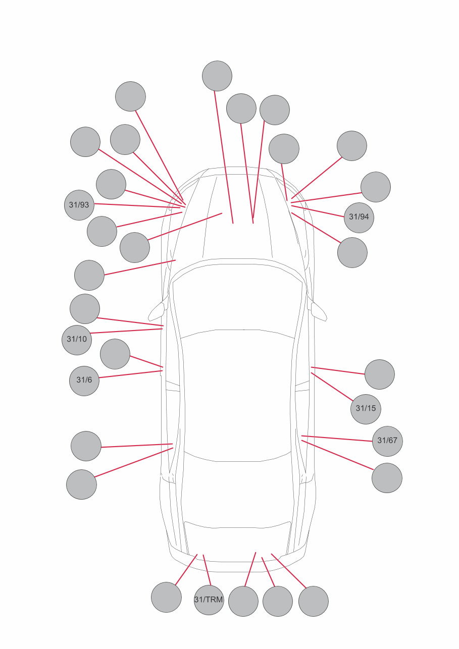
TP39260202 S60 (11-), V60, XC60, S80 (07-), V70 (08-) & XC70 2013 3 Vehicles with SRS (Airbag)/SIPS bag/IC (Inflatable curtain) .......................................................... 2 Explanations & Abbreviations ........................................ 4 How to use the wiring diagrams 1:2............................... 5 Fuses S80, V70 & XC70 Distribution box in engine compartment F32-F40........... 7 Fuses S60/V60 Distribution box in engine compartment F32 - F40 ......... 8 Fuses XC60 Distribution box in engine compartment F32-F38........... 9 Ground connections Overview S80/V70 ....................................................... 10 Ground connections S80/V70...................................... 11 Overview S60/V60 ....................................................... 12 Ground connections S60/V60...................................... 13 Overview XC60............................................................ 14 Ground connections XC60........................................... 15 Group 28 Ignition and control system, S80/ V70 Engine management system, 4-Cyl. Turbo 1.6l 1:2..... 16 Engine management system, 4-Cyl. Turbo 2.0l 1:2..... 18 Engine management system, 4-Cyl. 1,6L Diesel 1:3... 20 Group 28 Ignition and control system, S60/ V60 Engine management system 4-Cyl. 1.6l Turbo 1:2...... 23 Engine management system 4-Cyl. 2.0l Turbo 1:2...... 25 Engine management system, 4-Cyl. 1,6L Diesel 1:3... 27 Group 28 Ignition and control system XC60 Engine management system, 4-Cyl. Turbo 2.0l 1:2..... 30 Connectors 74/301 - 74/310, S80/V70 ............................................ 32 74/310, S80/V70 .......................................................... 33 74/301 - 74/310, S60/V60 ............................................ 34 74/310, S60/V60 .......................................................... 35 74/310, XC60 ............................................................... 36 Branching points ....................................... 37 Index ............................................................ 38 List of components .................................... 39 Table of Contents
TP39260202 S60 (11-), V60, XC60, S80 (07-), V70 (08-) & XC70 2013 4 Explanations & Abbreviations Groups Group 26 = Cooling system Group 27 = Engine controls Group 28 = Ignition and control system Group 32 = Alternator and voltage regulator Group 33 = Starting system Group 35 = Lighting Group 36 = Additional electrical equipment Group 37 = Wiring and fuses Group 38 = Instruments Group 39 = Other Group 43 = Transmission Group 55 = Parking brake Group 59 = Brake system Group 64 = Steering Group 76 = Shock absorbers Group 83 = Doors and openings Group 84 = Exterior decorative elements, etc. Group 85 = Interior equipment Group 87 = Climate control system Group 88 = Internal equipment Group 89 = Body other Designations ignition switch X = Accessories (audio position) S = Powered upon insertion of key 15 = The switch remains connected during start 15l = Contact is broken while starting 30 = Constant power from the battery 50 = Start Countries/Markets A = Austria AUS = Australia B = Belgium CDN = Canada CH = Switzerland D = Germany DK = Denmark E = Spain EU/OS = Markets outside USA and Canada FIN = Finland GB = Great Britain ISR = Israel J = Japan KOR = Korea N = Norway NL = Netherlands S = Sweden USA = United States of America WEU = Western Europe Other ACC = Adaptive Cruise Control Ag = Silver plated Au = Gold plated AUTO = Automatic transmission BLIS = Blind Spot Information System CAN = CAN communication DPY = Display ECC = Electronic climate control system ETA = Throttle unit EXC = Exclusive GDL = Gas discharge lamp HS = High speed data bus KEYLESS = Keyless vehicle IR = Infrared sensor LIN = LIN communication LH = Left-hand side LHD = Left-hand drive MAN = Manual transmission MEMORY = Memory driver’s seat MIRCAM = Parking camera in rear-view mirror MS = Midspeed data bus MMS = Mass Movement Sensor PANROOF = Panoramic roof PETROL = Gasoline RH = Right-hand side RHD = Right-hand drive RTI = Road Traffic Information SCR = Screened SRS = Airbag T = Turbo engine W/O = Without 2WD = Two-wheel drive 4CYL, I4 = 4-cylinder engine 5CYL, I5 = 5-cylinder engine 6CYL, I6 = 6-cylinder engine Colors BK, SB = Black BN = Brown BU, BL = Blue GN = Green GY, GR = Gray LGN = Light Green NL = Natural OG, OR = Orange PK, P = Pink RD, R = Red VT, VO = Violet WH, W = White YE, Y = Yellow
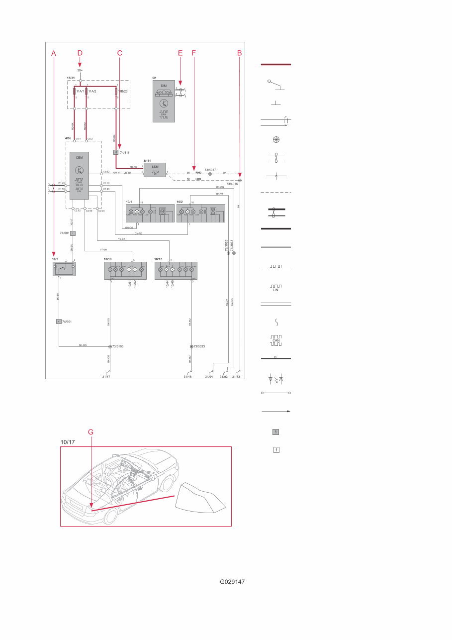
TP39260202 S60 (11-), V60, XC60, S80 (07-), V70 (08-) & XC70 2013 5 The descriptions below apply in general to all wiring diagram manuals, although not all sections are necessarily con- tained in this manual. The systems are shown in non-active status.i.e. with "key removed" and when the doors, hatches and hood are closed. How to use the wiring diagrams 1:2 A. Component designation Every component has a component designation that consists of two parts. The first part is a type number that describes the type of component in question, for example 3/xx. The second part of the designation is a serial num- ber, for example x/2. Combined these give a component designation, for example 3/2. At the end of the manual is a list of components, where, with the help of the component designation, you can read off the name of the component, for example, 3/2 = light switch. List of type numbers The list shows which type of component that respec- tive type numbers refer to, for example, 3/x = switch, 6/x = electric motor, etc. 1 Battery 2 Relay 3 Switch 4 Control module 5 Driver Information Module 6 Electric motor 7 Sensor 8 Actuator 9 Heating element 10 Light 11 Fuse 15 Electrical distribution rail/box 16 Audio 17 Service/diagnostics 18 Contact reel 19 Meter 20 Ignition component/shunt 27 Optics 31 Ground connection 73 Branching point 74 Connector B. Branching points The wiring diagrams contain numbered branching points, for example 73/5035. This manual contains a section with a list of branch- ing points. This list shows all the components which are connected to each branching point. The location of the branching points is shown in the "Cable harness routing in vehicle" section. C. Connectors Connectors provide a bridge between two cable har- nesses and are described in the "Connectors" sec- tion. D. Electrical distribution Operation of the fuses and relays is shown in the "Electrical distribution" section. E. Data communication Today’s cars contain CAN, LIN and MOST networks that transfer information. Connections to these net- works are not shown in their entirety in the respec- tive wiring diagram. Complete information on CAN, LIN and MOST communication is found in the sec- tion "Control modules". F. Abbreviations A number of different abbreviations are used in the manual. These are explained in the section "Abbre- viations". G. Component location There is a section at the end of the manual in which the appearance and location of components is described in numerical order.
TP39260202 S60 (11-), V60, XC60, S80 (07-), V70 (08-) & XC70 2013 6 How to use the wiring diagrams 2:2 Explanation of symbols = System voltage = Ground connection via wiring = Ground connection in component/chassis = Screened wire = Branching point = Twisted cable = Electrical connection = Variant = CAN communication = CAN high data signal (CAN H) = CAN low data signal (CAN L) = LIN communication = LIN communication = DIN cable, coaxial cable, etc. = Data communication = CAN communication = MOST communication = MOST communication = Connection with distribution box = Further connection to... = Connector between cable harnesses = Connector connected in component
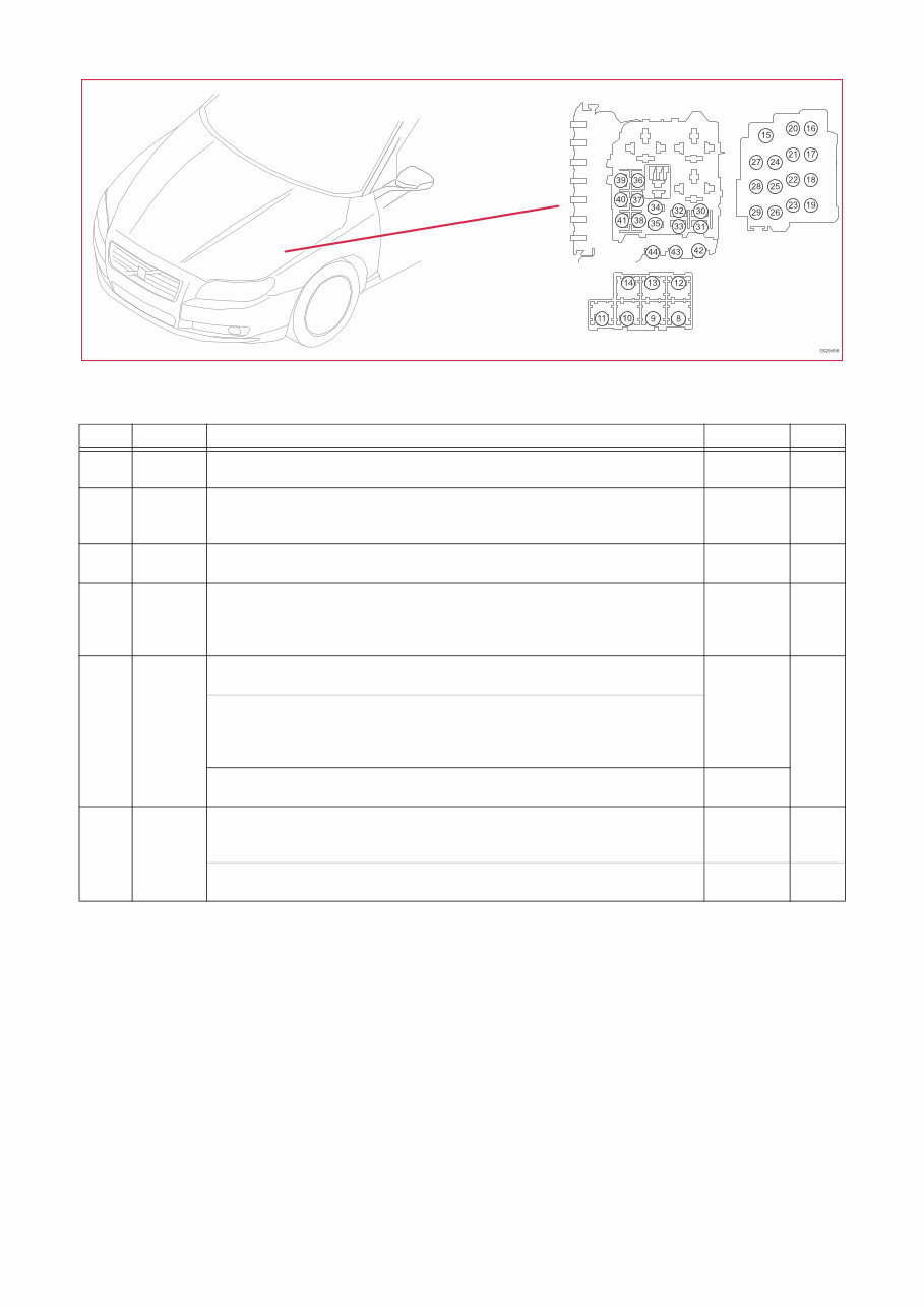
TP39260202 S60 (11-), V60, XC60, S80 (07-), V70 (08-) & XC70 2013 7 Fuses S80, V70 & XC70 Distribution box in engine compartment F32-F40 15/31 Distribution box in engine compartment No. No. Fuse function via A F32 11B/32 2/22 Relay, climate control system 8/3 Electromagnetic clutch, climate control system - 2/22 15 F33 11B/33 2/14 Relay, glow plug system 2/22 Relay, climate control system 4/46 Engine Control Module (ECM) - - - 5 F35 11B/35 20/3-6 Spark plug with ignition coil, 4-Cyl. 8/111 Control valve fuel flow - - 10 F37 11B/37 7/17 Mass airflow sensor (MAF), 4-Cyl. 8/111 Control valve fuel flow, 4-Cyl. Diesel 8/121 Radiator valve 8/167 Bypass solenoid - - - - 10 F38 11B/38 8/18 EVAP valve, 4-Cyl. 8/28 Turbocharger control valve, 4-Cyl. - - 10 7/17 Mass air flow sensor MAF, 4-Cyl. Turbo 8/19 Solenoid, variable valve timing, intake, 4-Cyl. Turbo 8/81 Solenoid, variable valve timing, exhaust, 4-Cyl. Turbo 8/159 Bypass valve - - - - 2/14 Relay, glow plug system 6/73 Coolant pump, Start/Stop, 4-Cyl. Diesel - 2/14 F40 11B/40 2/14 Relay, glow plug system 6/179 Electric oil pump 9/38 Heated fuel filter, Diesel - - - 20 2/14 Relay, glow plug system 6/73 Coolant pump, Start/Stop, 4-Cyl. Turbo - 2/14 10
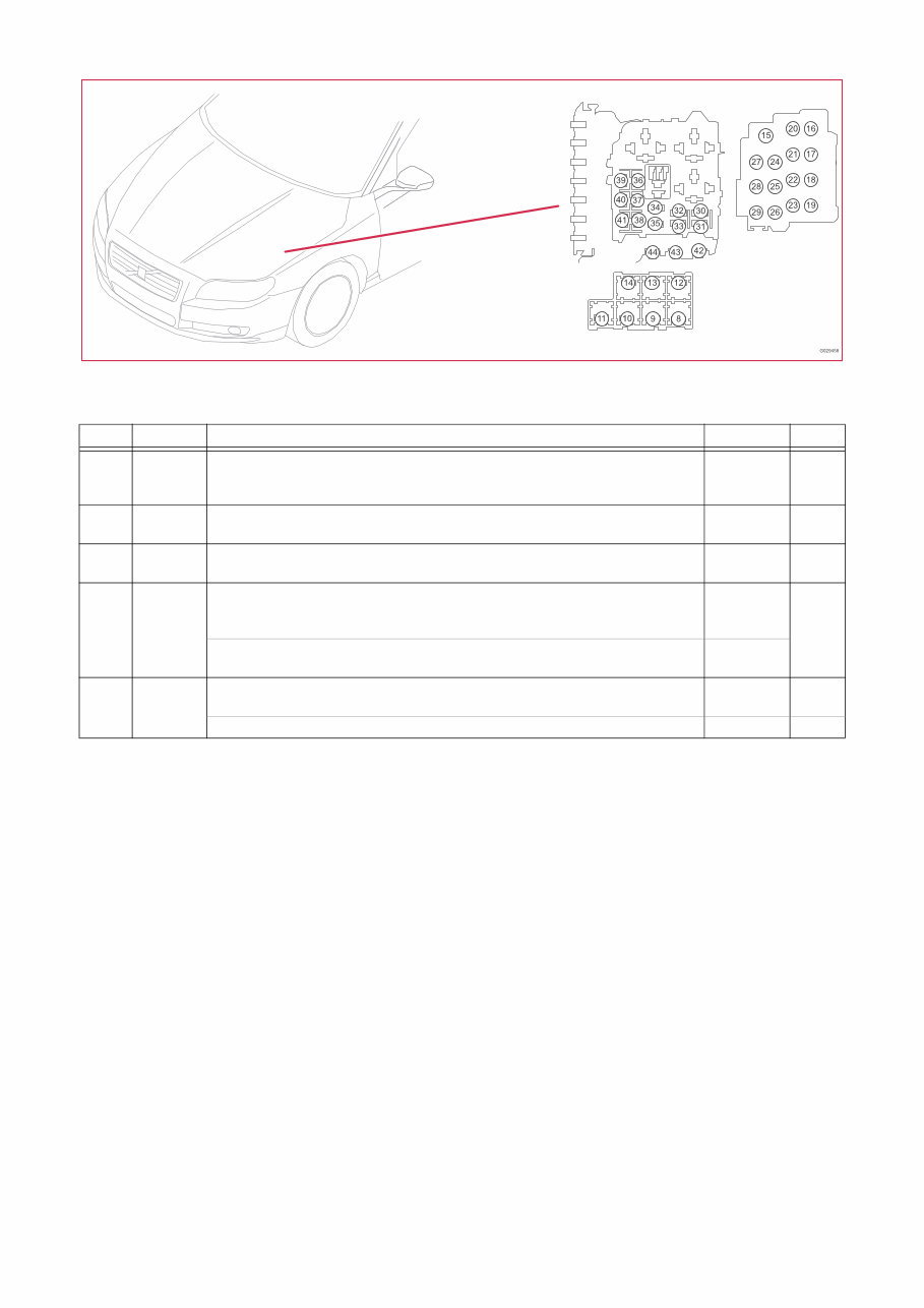
TP39260202 S60 (11-), V60, XC60, S80 (07-), V70 (08-) & XC70 2013 8 Fuses S60/V60 Distribution box in engine compartment F32 - F40 15/31 Distribution box in engine compartment No. No. Fuse function via A F32 11B/32 2/22 Relay, climate control system 6/73 Coolant pump, Start/Stop 8/3 Electromagnetic clutch, climate control system - 2/22 2/22 15 F33 11B/33 2/14 Relay, glow plug system 2/22 Relay, climate control system - - 5 F35 11B/35 4/109 Glow plug control module, 5-Cyl. Diesel 20/3-6 Spark plug with ignition coil, 4-Cyl - - 10 F37 11B/37 7/17 Mass air flow sensor MAF, 4-Cyl. 1.6l Turbo 8/121 Bypass valve charge air cooler, 4-Cyl. 1.6l Turbo 8/167 Bypass Solenoid, 4-Cyl. 1.6l Turbo - - - 10 7/17 Mass air flow sensor MAF, 4-Cyl. 1.6l Diesel 8/111 Control valve fuel flow, 4-Cyl. 1.6l Diesel - - F40 11B/40 2/14 Relay, glow plug system 6/73 Coolant pump, 4-Cyl. Turbo, Start/Stop 2/14 10 9/38 Electrically heated fuel filter, 4-Cyl. Diesel 2/14 20
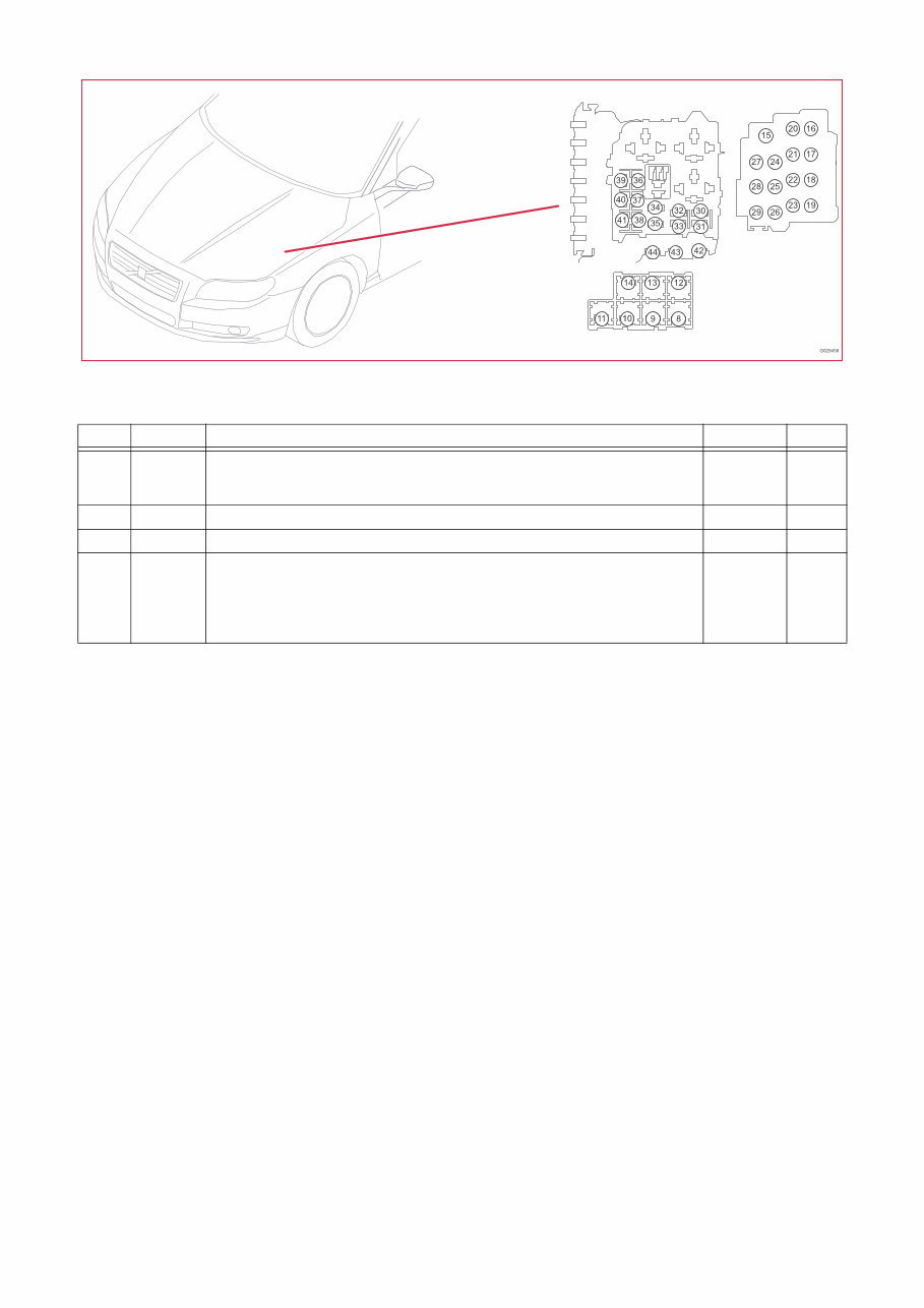
TP39260202 S60 (11-), V60, XC60, S80 (07-), V70 (08-) & XC70 2013 9 Fuses XC60 Distribution box in engine compartment F32-F38 15/31 Distribution box in engine compartment No. No. Fuse function via A F32 11B/32 2/22 Relay, climate control system 6/73 Coolant pump 8/3 Electromagnetic clutch, climate control system 2/22 2/22 15 F33 11B/33 2/22 Relay, climate control system - 5 F35 11B/35 20/3-6 Spark plug with ignition coil, 4-Cyl. Turbo - 10 F38 11B/38 7/17 Mass air flow sensor MAF, 4-Cyl. Turbo 8/18 EVAP valve, 4-Cyl. Turbo 8/19 Solenoid, variable valve timing, intake, 4-Cyl. Turbo 8/28 Turbocharger control valve, 4-Cyl. Turbo 8/81 Solenoid, variable valve timing, exhaust, 4-Cyl. Turbo - - - - - 10
The Volvo XC60 2013 Electrical Wiring Diagram Manual INSTANT is a comprehensive guide for understanding and repairing the electrical systems of the Volvo XC60 models from the year 2013. This manual provides detailed diagrams and instructions for all electrical components, wiring circuits, and connectors.
With this manual, users can easily diagnose and fix any electrical issues in their Volvo XC60 vehicles. Whether it's troubleshooting a malfunctioning electrical system or installing new components, this manual provides step-by-step instructions and visuals to ensure a successful repair.
Models covered:
Volvo XC60 2013
Key features of the Volvo XC60 2013 Electrical Wiring Diagram Manual INSTANT:
Clear and detailed diagrams for all electrical systems
Comprehensive wiring circuit information
Easy-to-follow instructions for repairing and installing electrical components
Instant access, no waiting time for delivery
Whether you're a professional mechanic or a Volvo XC60 owner who likes to DIY, this manual is a must-have for maintaining and servicing your vehicle's electrical systems. Trust the Volvo XC60 2013 Electrical Wiring Diagram Manual INSTANT to provide you with accurate and reliable information for all your electrical repair needs.






 Lifetime Access




