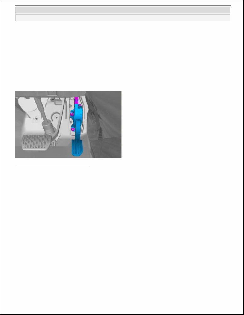
ENGINE Engine Control - Removal, Replacement And Installation ACCELERATOR PEDAL REMOVAL Fig. 1: Identifying Accelerator Pedal Courtesy of VOLVO CARS CORPORATION Torque: M6 10 Nm INSTALLATION To install, reverse the removal procedure. NOTE: Removal steps in this procedure may contain installation details. 2010 Volvo S80 ENGINE Engine Control - Removal, Replacement And Installation
ACCESSORIES AND EQUIPMENT Other Electrical Equipment - Installation Instructions, Accessories CRUISE CONTROL CARS EQUIPPED WITH SRS/SIPS (AIRBAG) (2007-09) Is the car equipped with SRS (supplemental restraint system)? Cars equipped with a driver's airbag have the letters "SRS" embossed on the center panel of the steering wheel. Cars equipped with driver's and passenger airbags are marked with "SRS" on both the steering wheel center panel and also on the dashboard close to the airbag. If the car has SIPS cushions, both front seats have "SIPS" stitched into the upholstery. Cars equipped with inflatable curtains have the marking "SRS" on one of the panels along the posts on the inside of the car. Cars equipped with SRS (supplemental restraint system) also have an "SRS" decal on the front windscreen. Do not damage the SRS wiring. Do not trap, chafe, pierce or damage the SRS wiring. SRS wiring has orange casing and/or is plaited. Steering and front suspension The contact reel in the SRS system can easily be damaged when working on the steering wheel, steering shaft or steering gear. Refer to service instructions in VIDA (Volvo Scan Tool) for information on carrying out such work. This is to prevent damage. WARNING: Extra care must be taken when working on cars equipped with SRS/SIPS airbags. This is important to prevent: 1. Personal injury 2. Damage to or malfunction of the SRS/SIPS system. Work on the SRS/SIPS systems or related components must always be carried out by an authorized Volvo workshop. WARNING: The airbag inflation areas must not be obstructed. Never place any objects, such as upholstery or accessories, within these areas. The panels must be able to open in the correct manner at the right time, otherwise there is an increased risk of personal injury in the event of a collision. 2010 Volvo S80 ACCESSORIES AND EQUIPMENT Other Electrical Equipment - Installation Instructions, Accessories
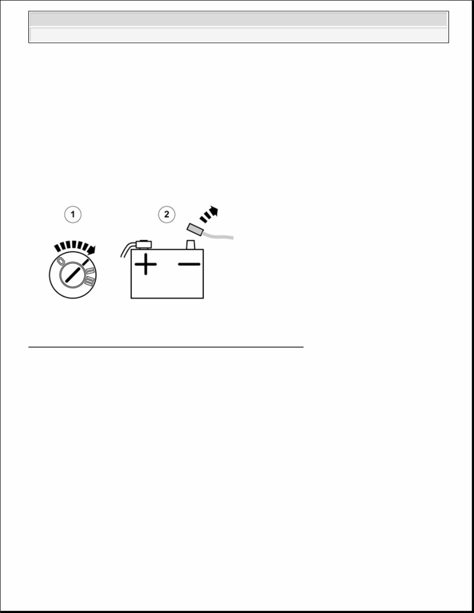
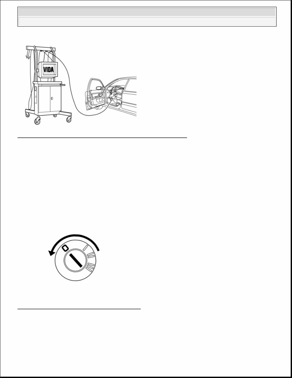
SRS warning lamp If the SRS warning lamp lights after repairs have been carried out, take the car to an authorized Volvo workshop. Control module The supplemental restraint system module (SRS) is located on the tunnel under the center console CRUISE CONTROL Fig. 1: View Of Ignition Key In Position I And Battery Negative Lead Courtesy of VOLVO CARS CORPORATION Turn the ignition key to position I to release the steering wheel lock. Disconnect the battery negative lead. NOTE: The SRS system remains active for a brief period after power is cut off. Thus, wait 3 minutes before starting work. 2010 Volvo S80 ACCESSORIES AND EQUIPMENT Other Electrical Equipment - Installation Instructions, Accessories
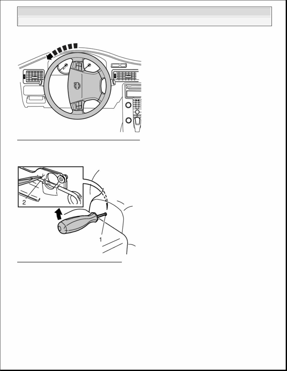
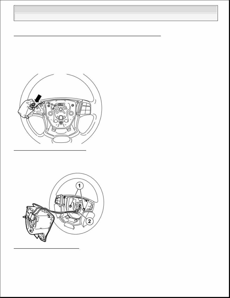
Fig. 2: View Of Steering Wheel At A Quarter Turn Courtesy of VOLVO CARS CORPORATION Turn the steering wheel a quarter turn so that the holes on the reverse of the steering wheel are accessible. Fig. 3: Identifying Screwdriver In The Hole Courtesy of VOLVO CARS CORPORATION Insert a screwdriver in the hole (1) on the reverse of the steering wheel, at right angles to the rear surface of the steering wheel. Insert the screwdriver as far as possible to determine the position of the end of the spring clip (2). Position the end of the screwdriver on the top of the spring clip as shown. Pry the screwdriver upwards towards the upper edge of the hole (1) so that the end of the screwdriver presses the spring clip down (2) until one side of the steering wheel module springs out and releases from the mounting. Turn the steering wheel a half turn in the opposite direction. Carry out the same operation on the other side 2010 Volvo S80 ACCESSORIES AND EQUIPMENT Other Electrical Equipment - Installation Instructions, Accessories
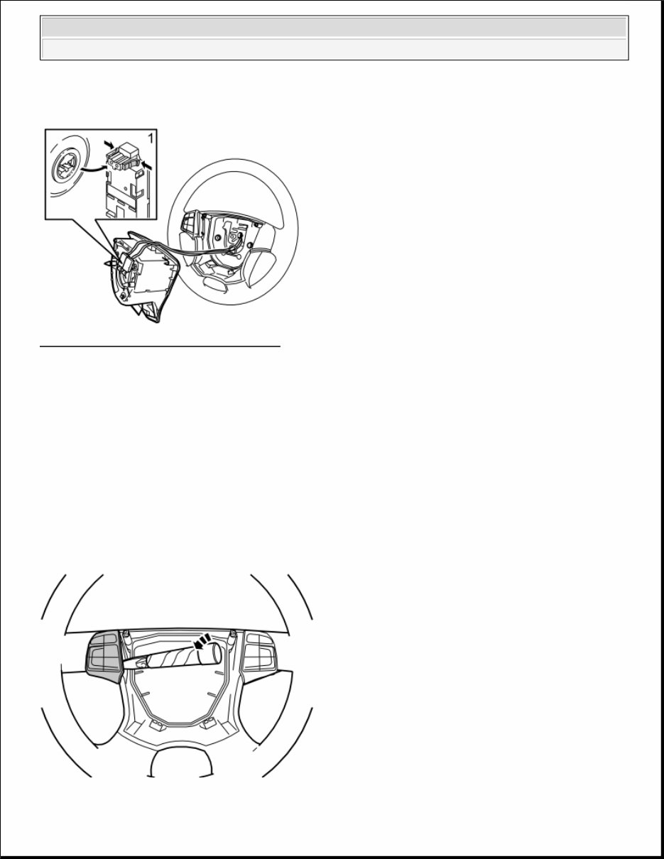
Turn the steering wheel to a neutral position. Fig. 4: Folding Out Steering Wheel Module Courtesy of VOLVO CARS CORPORATION Fold the steering wheel module out. Remove the two connectors (1) for the ignition cables for the airbag. First press in the catches on the sides. Then pull the connectors straight out. Place the steering wheel module to one side. NOTE: The connectors are tightly secured. However, tools must not be used when removing. WARNING: Position the steering wheel module with the front upwards in a secure position while carrying out the work. 2010 Volvo S80 ACCESSORIES AND EQUIPMENT Other Electrical Equipment - Installation Instructions, Accessories
Fig. 5: Remove The Left Keypad/Keypad Dummy From The Steering Wheel Courtesy of VOLVO CARS CORPORATION Remove the left keypad/keypad dummy from the steering wheel by carefully prying it off using a plastic weatherstrip tool. Twist the weatherstrip tool to pry it out. The keypad/keypad dummy is firmly held in place by three lugs in the steering wheel, so some force is required to remove it. Disconnect the connector and place it to one side. The connector will not be reused. Fig. 6: Identifying Keypad Connector Courtesy of VOLVO CARS CORPORATION Take the new keypad from the kit. Plug in the connector and press the keypad into the steering wheel. Fig. 7: Identifying Ignition Cables Courtesy of VOLVO CARS CORPORATION Check that the two springs (1) are in position. Check that the ignition cables are correctly positioned in the holder (2). 2010 Volvo S80 ACCESSORIES AND EQUIPMENT Other Electrical Equipment - Installation Instructions, Accessories
Position the steering wheel module and press the two connectors to the ignition cables for the airbag. Insert the two pins on the reverse of the steering wheel module in the two springs. Ensure that the ignition cables are not trapped Press the steering wheel module firmly into its mountings. Two clearly audible clicks should be heard. INSTALLING THE NEGATIVE LEAD AFTER WORKING WITH SRS COMPONENTS Fig. 8: VIDA Logo Courtesy of VOLVO CARS CORPORATION Install the negative cable according to VIDA (Volvo Scan Tool): Repair Clean, check and adjust 3 Electrical system 31 Battery and installation components 311 Battery Battery Battery, disconnection WARNING: Make sure that no one is in the vehicle when this is done. 2010 Volvo S80 ACCESSORIES AND EQUIPMENT Other Electrical Equipment - Installation Instructions, Accessories
Fig. 9: Identifying VIDA (Service Information) To Program Software Courtesy of VOLVO CARS CORPORATION Download the software (application) for the accessory's function following the service information in VIDA (Volvo Scan Tool). See VIDA (Volvo Scan Tool) or the accessories catalog for software part number. ALARM, SWITCH REMOVAL Fig. 10: Identifying Turning Ignition To Position 0 Courtesy of VOLVO CARS CORPORATION Turn the ignition key to position 0. 2010 Volvo S80 ACCESSORIES AND EQUIPMENT Other Electrical Equipment - Installation Instructions, Accessories
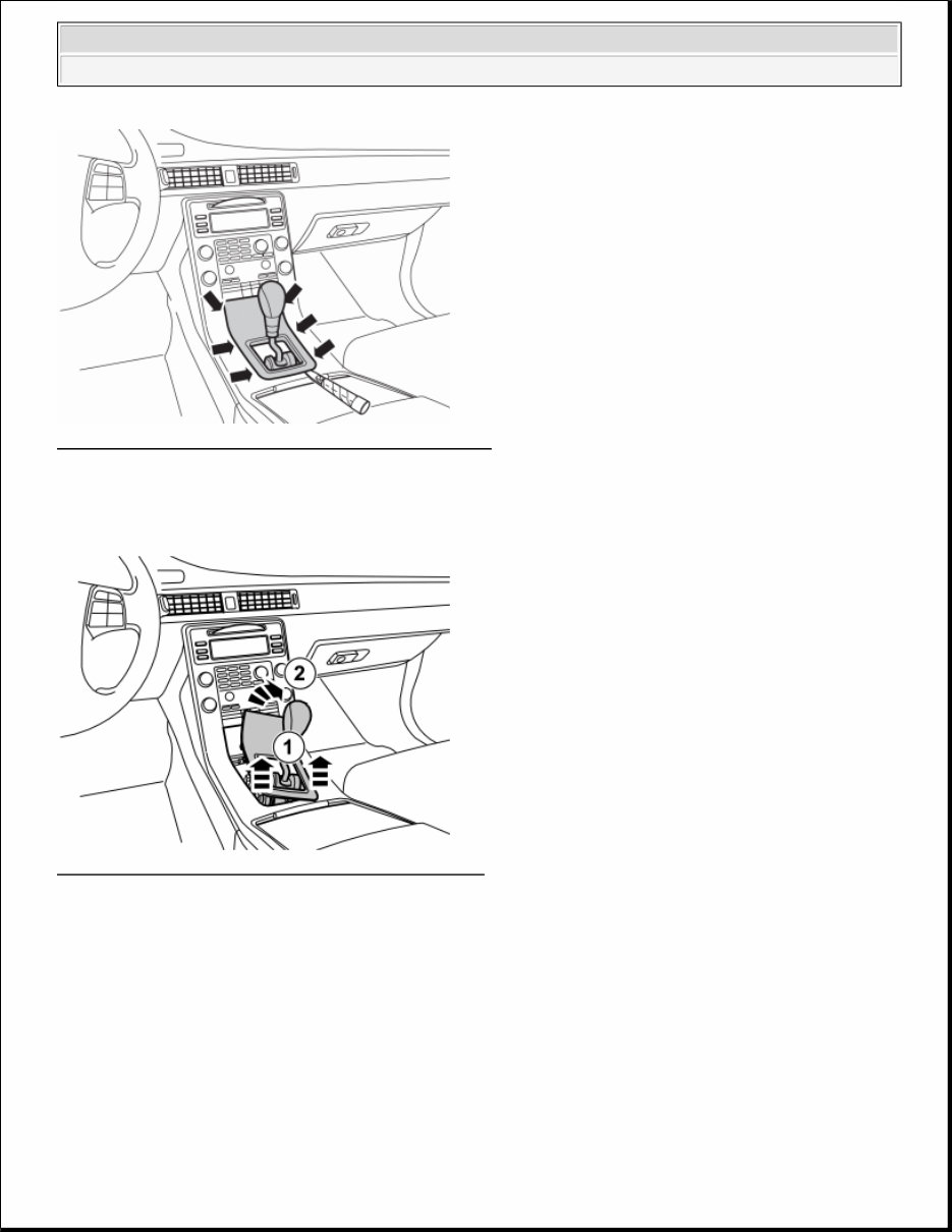
Fig. 11: Identifying Panel Around Gear Selector Lever Courtesy of VOLVO CARS CORPORATION Carefully prize away the panel around the gear selector lever using a weatherstrip tool. It is secured along the longitudinal sides with six catches. Start prizing in the rear edge of the panel. Fig. 12: Removing Panel Around Gear Selector Lever Courtesy of VOLVO CARS CORPORATION Twist/remove the panel, so that the row with switches/dummy buttons is accessible. 2010 Volvo S80 ACCESSORIES AND EQUIPMENT Other Electrical Equipment - Installation Instructions, Accessories
Whether you're a professional mechanic or a DIY enthusiast, this repair manual equips you with the necessary resources to address vehicle issues. It encompasses troubleshooting and replacement procedures recommended by the manufacturer, complete with step-by-step instructions, clear images, and exploded-view illustrations.
While your vehicle boasts durability, regular maintenance is essential. Over time, certain parts will wear out and require replacement. This manual serves as a valuable resource, offering the manufacturer's recommended troubleshooting charts and replacement procedures, ultimately enabling you to save on repairs, enhance your vehicle's reliability, and minimize visits to the repair shop.
Featuring comprehensive troubleshooting and replacement procedures, along with step-by-step instructions, exploded-view illustrations, and clear images, this manual eliminates the need to sift through numerous pages to locate specific information. It provides a convenient alternative to traditional bound manuals, allowing easy access, searchability, and portability on electronic devices such as PCs, Mac computers, smartphones, and tablets. Additionally, it is printable for those who prefer physical copies.
Printable: Yes Language: English Compatibility: Various electronic devices including PCs, Mac computers, Android and Apple smartphones, and tablets Requirements: Adobe Reader (free)