
 Wiring Diagram")
2007 VOLVO S80 (07-) Wiring Diagram
What's Included?
Fast Download Speeds
Offline Viewing
Access Contents & Bookmarks
Full Search Facility
Print one or all pages of your manual
S80 (07-)
VOLVO
2007
TP 39100202

© Volvo Car Corporation
Vehicles with SRS (Airbag)/SIPS bag/
IC (Inflatable curtain)
Warning!
Extra caution must be exercised when working on vehicles equipped with SRS/SIPS bag/IC
in order to avoid:
1. Personal injuries when performing repair work.
2. Damage or malfunction of the SRS/SIPS bag/IC system.
Work involving the SRS/SIPS bag/IC systems or other components in the vehicle that may
affect the SRS/SIPS bag/IC systems must always be performed by an authorized Volvo
workshop.
In case of doubt, consult the SRS and SIPS bag/IC service manual.
Is the vehicle equipped with SRS/SIPS bag/IC?
Vehicles with SRS are most easily recognized by the letters SRS in the center of the steering
wheel. If the vehicle also has a passenger side airbag, the letters SRS are stamped on the
dashboard above the glove compartment. SRS vehicles from 1993 and onward also have
explosive
seat belt tensioners. SIPS bags are only installed on SRS vehicles from 1995 and onward.
SIPS bag decals are located on the windshield and seat compartment. Vehicles with IC can be
recognized by the letters IC on the C/D panel (4 door) or the B panel (5 door).
General recommendations
• Be especially careful when working on or around SRS, SIPS, and IC components.
• Make sure that no wires are pinched, frayed, or pierced.
• Never fit accessories by the sensors.
• Where applicable, work on the steering wheel, steering shaft, or steering gear must be done
in accordance with the methods in the SRS section of VIDA.
• Certain components of the aforementioned systems must be grounded while working. Read
the appropriate sections in VIDA.
• Do not install any accessories in the areas between the A and B-posts, the B and C-posts,
and the C and D-posts.
Test terminal
Fuse in cargo compartment auxiliary fuse box
Changes introduced up to April 2006
Any changes made to the vehicle after this date are not included in the
manual. If necessary, refer to service bulletins.
Volvo models are sold in versions adapted for different markets. These
adaptations depend on factors such as legal requirements, taxation, and
market demands.
This manual may therefore include illustrations and text that do not apply to
the vehicles in your country.
Order number TP 39100202
Replaces previous publication 39100201 at Electronic Wiring Diagram (EWD)
TP 39101001
Can also be found at Electronic Wiring Diagram (EWD) TP 39102001

TP39100202 S80(07-) 2007 3
Vehicles with SRS (Airbag)/SIPS bag/
IC (Inflatable curtain) ..................................................... 2
Explanations .................................................................. 5
Abbreviations ................................................................. 5
How to use the wiring diagrams 1:2............................... 6
Electrical distribution 1:2 ................................................ 8
Fuses
Engine compartment electrical center F1-F7 ................ 10
Engine compartment electrical center F9-F21 .............. 11
Engine compartment electrical center F22-F34 ............ 12
Engine compartment electrical center F35-F38 ............ 13
Engine compartment electrical center F39-F44 ............ 14
Central Electronic Module (CEM) F1-F15..................... 15
Central Electronic Module (CEM) F17-F28................... 16
Rear electrical center FA1-FA11 .................................. 17
Rear electrical center FB1-FB7 .................................... 18
Rear electrical center FC2-FC7 .................................... 19
Rear electrical center FD1-FD7 .................................... 20
Battery PF1-PF2 ........................................................... 21
Relays
Relays in the engine compartment R2......................... 22
Relays in the engine compartment R8-R9 ................... 23
Relays in the engine compartment R10-R13 ............... 24
Rear electrical center RA1-RB2................................... 25
Central Electronic Module (CEM) ................................ 26
Ground connections
Overview...................................................................... 27
31/1 - 31/7 ................................................................... 28
31/10 - 31/15 ............................................................... 29
31/47 - 31/68 ............................................................... 30
31/83 - 31/89 ............................................................... 31
31/90 - 31/100 ............................................................. 32
31/XX4 - 31/AL ............................................................ 33
Control modules
Overview of locations................................................... 34
Overview of designations............................................. 35
Central Electronic Module (CEM) 1:3 ........................ 36
High speed CAN data communication ....................... 39
Midspeed CAN data communication, LHD .................. 40
Midspeed CAN data communication, RHD.................. 41
LIN data communication 1:2 ...................................... 42
MOST data communication ...................................... 44
Steering Wheel Module (SWM) ................................... 45
Group 23 Fuel system
Engine management system, 5 cyl. 2.5l turbo 1:2 ....... 46
Engine management system, 6 cyl. 1:2 ....................... 48
Engine management system, 8 cyl. 1:2 ....................... 50
Engine management system, 5 cyl. 2.4l diesel 1:3...... 52
Emission control, 5 cyl. 2.4l turbo ................................ 55
Emission control, 6 cyl. ................................................ 56
Emission control, 8 cyl. ................................................ 57
Group 26 Cooling system
Cooling fan, 5 cyl. - 6 cyl.............................................. 58
Cooling fan, 5 cyl. 2.4l diesel ....................................... 59
Cooling fan, 8 cyl. ........................................................ 60
Group 32 Generator and voltage regulator
Power supply ............................................................... 61
Group 33 Starting system
Starting system ............................................................ 62
Group 35 Lighting
High and low beam ...................................................... 63
High and low beam (Bi-Xenon) .................................... 64
Beam length adjustment, manual ................................ 65
Beam length adjustment, automatic (Bi-Xenon) .......... 66
Active headlights .......................................................... 67
Running/parking lights, tail lights ............................... 68
Running/parking lights, Tail lights (Bi-Xenon) ............ 69
Fog lights ..................................................................... 70
Brake lights .................................................................. 71
Reversing lights ........................................................... 72
Lighting in sill moldings ................................................ 73
Follow-me-home lighting, LHD..................................... 74
Follow-me-home lighting, RHD .................................... 75
Interior lighting, LHD 1:2 .............................................. 76
Interior lighting, RHD 1:2.............................................. 78
Auxiliary lights .............................................................. 80
Group 36 Additional electrical equipment
Rain sensor .................................................................. 81
Direction indicators and hazard warning flashers,
LHD ........................................................................ 82
Direction indicators and hazard warning flashers,
RHD ........................................................................ 83
Windshield wiper/washer ............................................. 84
High-pressure headlight washer .................................. 85
Horn ........................................................................ 86
Anti-theft alarm ............................................................ 87
Keyless vehicle 1:2 ...................................................... 88
Parking assistance....................................................... 90
Collision warning with brake servo............................... 91
Table of Contents 1:2

TP39100202 S80(07-) 2007 4
Group 37 Wiring and fuses
Diagnostics system...................................................... 92
12V outlet .................................................................... 93
Tow hitch cable harness, 4-pin .................................... 94
Tow hitch cable harness, 7-pin .................................... 95
Tow hitch cable harness, 13-pin ................................. 96
Group 38 Instruments
Seat belt reminder ....................................................... 97
Driver information module............................................ 98
Group 39 Other
Audio Premium 1:3 ...................................................... 99
Audio 1:2 ................................................................. 102
Cellular phone 1:2 .................................................... 104
Bluetooth phone system ............................................ 106
Multimedia & traffic information .............................. 107
Satellite radio ............................................................. 108
Group 43 Transmission
M66 transmission....................................................... 109
Automatic transmission TF-80SC AWD..................... 110
Differential Electronic Module (DEM)......................... 111
Group 55 Parking brake
Electronic parking brake ............................................ 112
Group 59 Brake system
Brake control system & DSTC ................................... 113
Group 64 Steering
Electronic power steering .......................................... 114
Group 76 Shock absorbers
Four-C ...................................................................... 115
Group 83 Doors and openings
Central locking, front doors, LHD............................... 116
Central locking, front doors, RHD .............................. 117
Central locking, rear doors......................................... 118
Central locking, trunk lid ............................................ 119
Central locking, fuel filler flap ..................................... 120
Signal receiver, central locking .................................. 121
Front door power windows, LHD ............................... 122
Front door power windows, RHD............................... 123
Rear door power windows ......................................... 124
Power sunroof............................................................ 125
Group 84 Exterior decorative elements etc.
Power door mirrors, LHD ........................................... 126
Heated door mirrors, LHD.......................................... 127
Heated door mirrors with camera function, LHD........ 128
Power door mirrors, RHD .......................................... 129
Heated door mirrors, RHD ......................................... 130
Heated door mirrors with camera function, RHD ....... 131
Rear window defroster ............................................... 132
Group 85 Interior equipment
Power driver’s seat with memory function, LHD ...... 133
Power driver’s seat with memory function, RHD ...... 134
Power passenger seat, LHD ...................................... 135
Power passenger seat, RHD ..................................... 136
Heated front seats with fans ...................................... 137
Heated front seats without fans ................................. 138
Heated rear seats ...................................................... 139
Group 87 Climate control system
Climate control system, 5, 6 & 8 cyl. 1:2 .................... 140
Climate control system, 5 cyl. 2.4l diesel 1:2 ............. 142
Climate control system PTC element ....................... 144
Parking heater, auxiliary heater ................................. 145
Group 88 Internal equipment
Supplemental Restraint System (SRS) 1:2 ................ 146
Electrically adjustable head restraint ......................... 148
Automatic anti-dazzle rearview mirror ...................... 149
Connectors............................................... 150
Branching points ..................................... 176
Cable harness routing in vehicle
Engine harness, 5 cyl. ................................................ 191
Engine harness, 6 cyl. ................................................ 191
Engine harness, 8 cyl. ................................................ 192
Engine harness, diesel ............................................... 192
Engine compartment harness ..................................... 193
Dashboard harness, LHD ........................................... 194
Dashboard harness, RHD........................................... 195
Floor harness, LHD..................................................... 196
Floor harness, RHD .................................................... 197
Infotainment harness, LHD ......................................... 198
Infotainment harness, RHD......................................... 199
Center console harness .............................................. 200
Roof harness .............................................................. 200
Tunnel harness ........................................................... 201
Left front door harness ................................................ 202
Right front door harness ............................................. 202
Left rear door harness ................................................ 203
Right rear door harness .............................................. 203
Trunk lid harness ........................................................ 204
Rear axle harnesses ................................................... 204
Component illustrations .......................... 205
Index 1:2 .................................................... 256
List of components 1:6 ............................ 258
Table of Contents 2:2

TP39100202 S80(07-) 2007 5
Explanations
Abbreviations
Groups
Group 23 = Fuel system
Group 26 = Cooling system
Group 27 = Engine controls
Group 32 = Generator and voltage regulator
Group 33 = Starting system
Group 35 = Lighting
Group 36 = Additional electrical equipment
Group 37 = Wiring and fuses
Group 38 = Instruments
Group 39 = Other
Group 43 = Transmission
Group 59 = Brake system
Group 64 = Steering
Group 83 = Doors and openings
Group 84 = Exterior decorative elements etc.
Group 85 = Interior equipment
Group 87 = Climate control system
Group 88 = Internal equipment
Ignition switch symbols
X = Accessories (audio position)
S = Powered upon insertion of key
15 = Contact remains connected during
start
15l = Contact is broken while starting
30 = Constant power from the battery
50 = Start
Countries/Markets
A = Austria
AUS = Australia
B = Belgium
CDN = Canada
CH = Switzerland
D = Germany
DK = Denmark
E = Spain
EU/OS = Markets outside USA and Canada
FIN = Finland
GB = Great Britain
ISR = Israel
J = Japan
KOR = Korea
N = Norway
NL = Netherlands
S = Sweden
USA = United States of America
WEU = Western Europe
Other
AUTO = Automatic transmission
CAN = CAN communication
DPY = Display
ECC = Electronic climate control system
ETA = Electronic throttle actuator
EXT. X = Extended X-feed
GDL = Gas discharge lamp
HISPEED = High speed data bus
IR = Infrared sensor
LIN = LIN communication
LH = Left-hand side
LHD = Left-hand drive
MAN = Manual transmission
MEMORY = Memory driver’s seat
MIDSPEED = Midspeed data bus
MMS = Mass movement sensor
PETROL = Gasoline
RH = Right-hand side
RHD = Right-hand drive
SCR = Screening
SRS = Airbag
T = Turbo engine
W/O = Without
2WD = Two wheel drive
5CYL, I5 = 5-cylinder engine
6CYL, I6 = 6-cylinder engine
8 CYL, V8 = 8-cylinder engine
Colors
BK, SB = Black
BN = Brown
BU, BL = Blue
GN = Green
GY, GR = Gray
LGN = Light Green
NL = Natural
OG, OR = Orange
PK, P = Pink
RD, R = Red
VT, VO = Violet
WH, W = White
YE, Y = Yellow

TP39100202 S80(07-) 2007 6
The descriptions below apply in general
to all wiring diagram manuals, although
not all sections are necessarily con-
tained in this manual.
How to use the wiring diagrams 1:2
A. Component designation
Every component has a component designation that
consists of two parts.
The first part is a type number that describes the
type of component in question, for example 3/xx.
The second part of the designation is a serial num-
ber, for example x/2.
Combined these give a component designation, for
example 3/2.
At the end of the manual is a list of components,
where, with the help of the component designation,
you can read off the name of the component, for
example, 3/2 = light switch.
List of type numbers
The list shows which type of component that respec-
tive type numbers refer to, for example, 3/x = switch,
6/x = electric motor, etc.
1 Battery
2 Relay
3 Switch
4 Control module
5 Driver Information Module
6 Electric motor
7 Sensor
8 Actuator
9 Heating element
10 Light
11 Fuse
15 Electrical distribution rail/box
16 Audio
17 Service/diagnostics
18 Contact reel
19 Meter
20 Ignition component/shunt
27 Optics
31 Ground connection
73 Branching point
74 Connector
B. Branching points
The wiring diagrams contain numbered branching
points, for example 74/5035.
This manual contains a section with a list of branch-
ing points. This list shows all the components which
are connected to each branching point.
The location of the branching points is shown in the
"Cable harness routing in vehicle" section.
C. Connectors
Connectors provide a bridge between two cable har-
nesses and are described in the "Connectors" sec-
tion.
D. Electrical distribution
Operation of the fuses and relays is shown in the
"Electrical distribution" section.
E. Data communication
Today’s cars contain CAN, LIN and MOST networks
that transfer information. Connections to these net-
works are not shown in their entirety in the respec-
tive wiring diagram. Complete information on CAN,
LIN and MOST communication is found in the sec-
tion "Control modules".
F. Abbreviations
A number of different abbreviations are used in the
manual. These are explained in the section "Abbre-
viations".
G. Component location
The end of the manual contains a section that
describes component appearance and location in
numerical order.

TP39100202 S80(07-) 2007 7
How to use the wiring diagrams 2:2
List of symbols
= System voltage
= Ground connection via cable
= Ground connection in
component/chassis
= Screened wire
= Branching point
= Twisted cable
= Electrical connection
= Variant
= CAN communication
= CAN high data signal (CAN H)
= CAN low data signal (CAN L)
= LIN communication
= LIN communication
= DIN cable, coaxial cable, etc.
= Data communication
= CAN communication
= MOST communication
= MOST communication
= Connection with distribution box
= Further connection to...
= Connector between cable
harnesses
= Connector connected in
component
LIN
CAN
1
1
G
A D E C F B
10/17
LIN
C1:50
C1:49
30+
1
CEM
4/56
2
11A/1
2
11A/2
C2:24
1 1
2
11B/23
15/31
C2:50
RD-BK
RD-BU
BK
BK
BK BK RHD
LHD
3
5
REV
GND
10/51
10/52
10/44
10/45
C5:2 C5:1
C1:10
C1:40
C3:52
31/83 31/93 31/94 31/47
GN-OG
GY-RD
YE-BK
VT-GN
CAN
10/3 10/18 10/17 2
1
4 74/601
1 74/601
73/5038
73/5030
BK-OG
BK-OG
BK-OG
BK-BU BK-BU
BN-BU YE-VT
C2:52
73/3033
73/4017
73/4016
73/3035
BK-OG
BK-VT
BK-OG
BK-VT
POS FOG STOP TURN
5
REV
GND
POS FOG STOP TURN
3
31/48
73/5033
BK-BU BK-BU
1
6 5
LIN
RD-BK
RD-BK
GN-VT
3/111
74/411 12
LSM
CAN
6
2
5/1
DIM
10/1
TURN POS HIGH LOW
1
10 10
M
10/2
TURN POS HIGH LOW
M
1
TP39100202 S80(07-) 2007 8
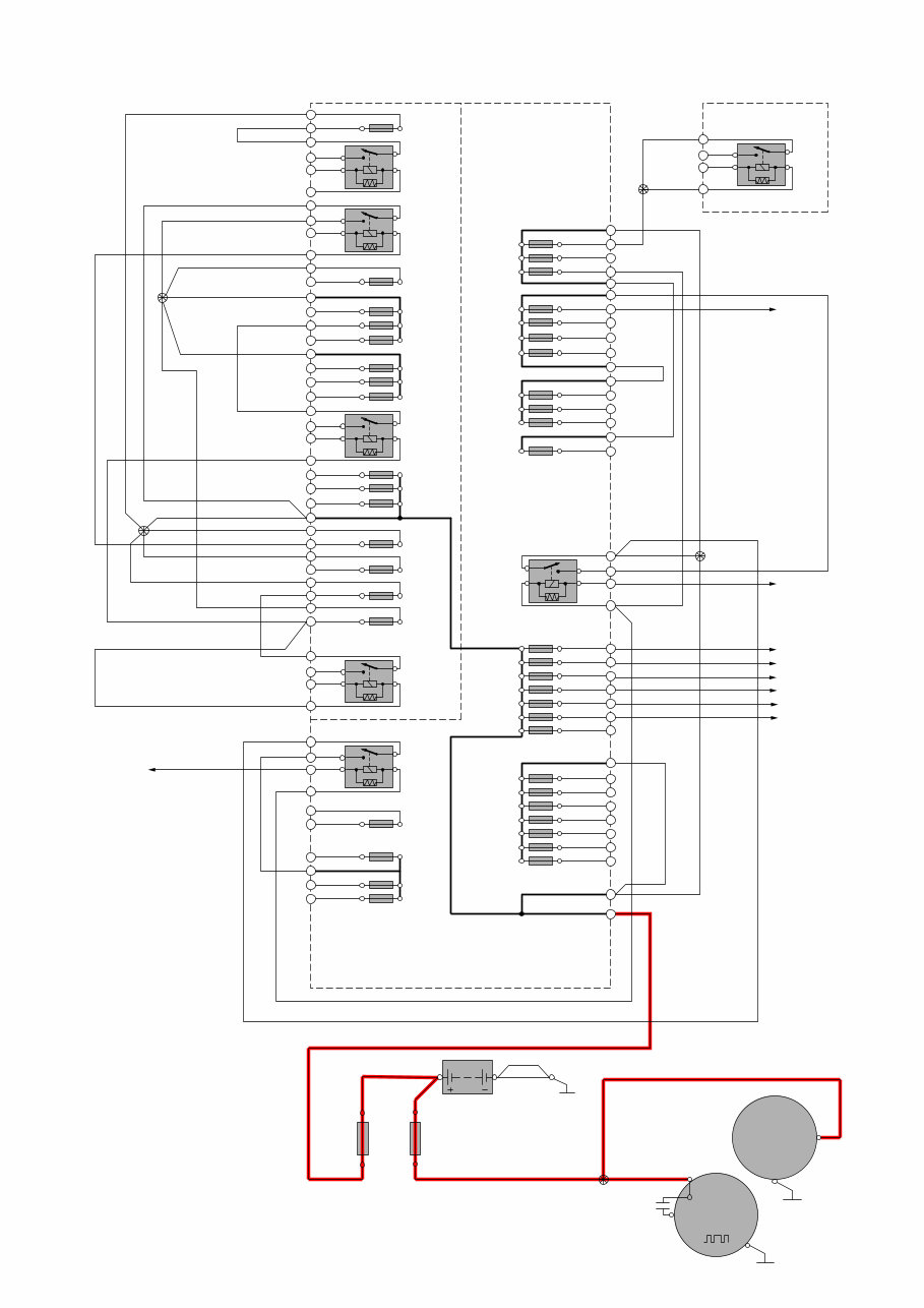
Electrical distribution 1:2
Overview, Electrical center and Cold zone in engine compartment
2 1
3
5 2/193
R9
15/31
15/33
11B/26
2 1
11B/25
2 1
11B/24
2 1
11B/36
2 1
11B/37
2 1
11B/38
2 1
11B/41
11B/18
1 2
11B/16
1 2
11B/17
73/3067
73/3068
73/3085
1 2
11B/19
1 2
11B/20
1 2
11B/21
1 2
11B/22
1 2
11B/23
1 2
11B/28
1 2
11B/29
1 2
RD-VT
RD-VT
RD-VT
RD
RD
RD
RD
GY-BK
RD
RD
GN-VT
RD-BK
RD_BU
RD-GN
RD-GY
RD-BN
15/32
15/32
15/32
4/56C5:2
4/56C5:1
RD
RD
RD RD
RD
RD
RD
RD-GY
VT-GN
4/56C1:48
RD
RD
RD
RD
RD
RD
RD
RD
RD
RD
RD
GY-VT
GY-VT
GY-VT
GY-VT
RD
RD-BK
RD
11B/27
1 2
11A/1
11A/2
11A/3
11A/4
11A/5
11A/6
1 2
11A/7
1 2
1 2
1 2
1 2
1 2
1 2
2 1
11B/40
2 1
11B/39
2 1
11A/43
2 1
11A/42
2 1
11A/44
2 1
11B/15
2 1
11B/33
2 1
11B/32
2 1
11B/31
2 1
11B/30
2 1
11B/35
2 1
11B/34
2 1
2 1
3
5 2/22
R13
2 1
3
5 2/239
R11
2 1
3
5 2/31
R8
2 1
3
5 2/32
R10
2 1
3
5 2/17
R2
2 1
3
5 2/35
R12
11B/13
11B/11
11B/9
11B/12
11B/10
1 2
11B/14
1 2
1 2
1 2
1 2
1 2
11B/8
1 2
73/3076
6/25
31
M
ACM
30
C1:1
6/26
B+
31
G
C1:1
12V BK
BK
31/3
1/1
PF1 PF2
2
1 1
2
LIN
9/42
4/56C1:45
4/56C1:65
73/3041
TP39100202 S80(07-) 2007 9
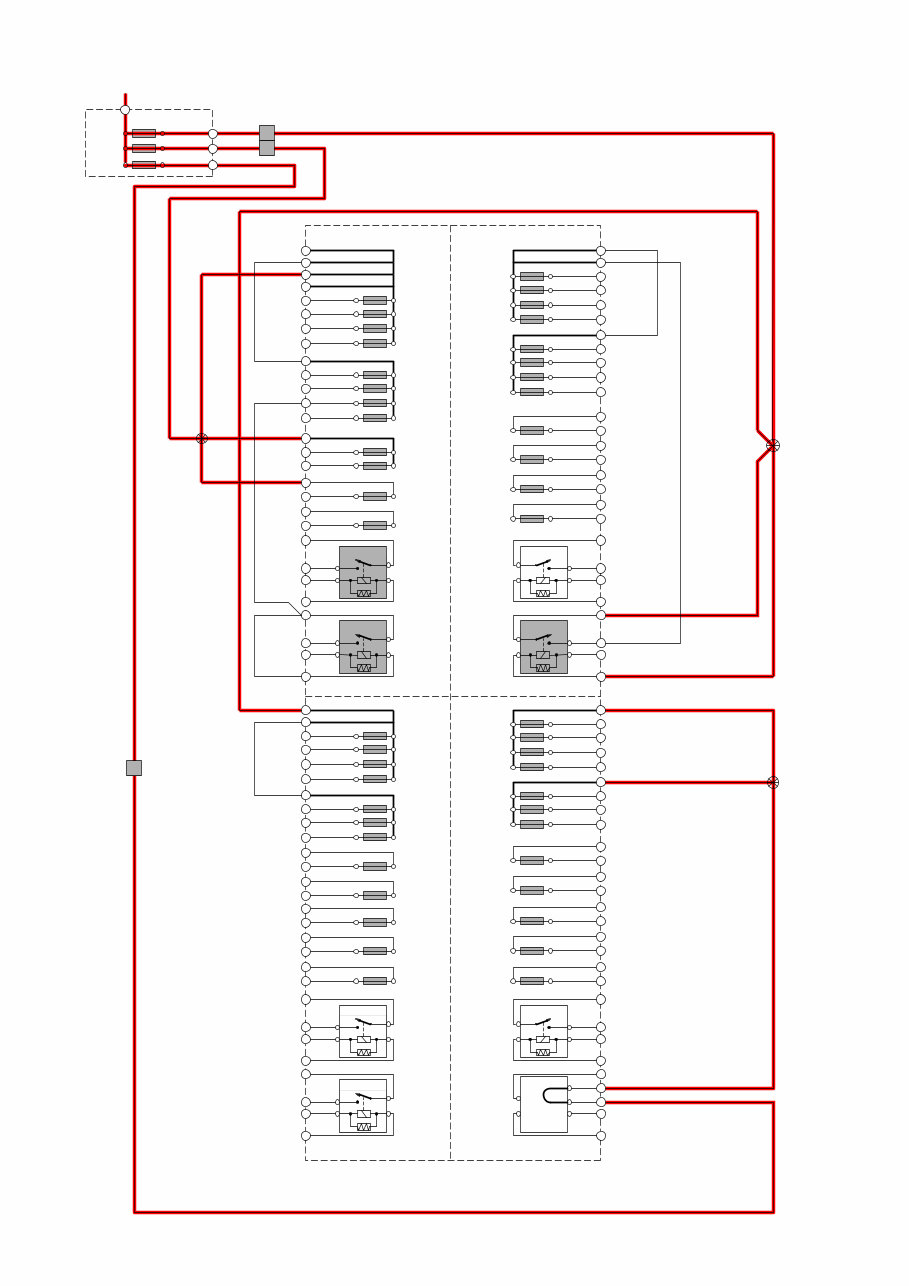
Electrical distribution 2:2
Overview, rear electrical center
73/5040
11D/C3
2 1
11D/C2
2 1
11D/C1
2 1
11D/C4
2 1
11D/C7
2 1
11D/C6
2 1
11D/C5
2 1
11D/A7
2 1
11D/A6
2 1
11D/A5
2 1
11D/A8
2 1
11D/A3
2 1
11D/A2
2 1
11D/A1
2 1
11D/A4
2 1
11D/A10
2 1
11D/A9
2 1
11D/A11
2 1
11D/A12
2 1
11D/C8
2 1
11D/C9
2 1
11D/C10
2 1
11D/C11
2 1
11D/C12
2 1
73/5069
2 1
3
5
2/75
2/82
15/32
15/31
RA2
2 1
3
5
A
BK NL
GY BU
B
C D
RA1
2 1
3
5
RC2
2 1
3
5
RC1
11D/B3
1 2
2
11D/B2
1 2
11D/B1
1 2
11D/B4
1
YE-VT
YE-VT
BU-RD
BU-RD
RD-BN
RD-BN
RD-GY
RD-GY
RD-GY
RD-GY RD-GY
11D/B7
1 2
11D/B6
1 2
11D/B5
1 2
11D/B8
1 2
11A/5 1 2
11A/3 1 2
11A/4
30+
74/504B
1 2
RD-GN
RD-GN
RD-BN
RD-GN
RD-GN
RD-GN
RD-GN
RD-VT
RD-GY
RD-VT
11D/B9
1 2
11D/B10
1 2
11D/B11
1 2
11D/B12
1 2
11D/D8
1 2
11D/D9
1 2
11D/D10
1 2
11D/D11
1 2
11D/D12
1 2
2 1
3
5
RB2
2 1
3
5
2/88
RB1
11D/D3
1 2
11D/D2
1 2
11D/D1
1 2
11D/D4
1 2
11D/D7
1 2
11D/D6
1 2
11D/D5
1 2
2 1
3
5
RD1
2 1
3
5
4
RD2
1
74/505
2
73/5075
1
TP39100202 S80(07-) 2007 10
1
2
3
4
5
6
7
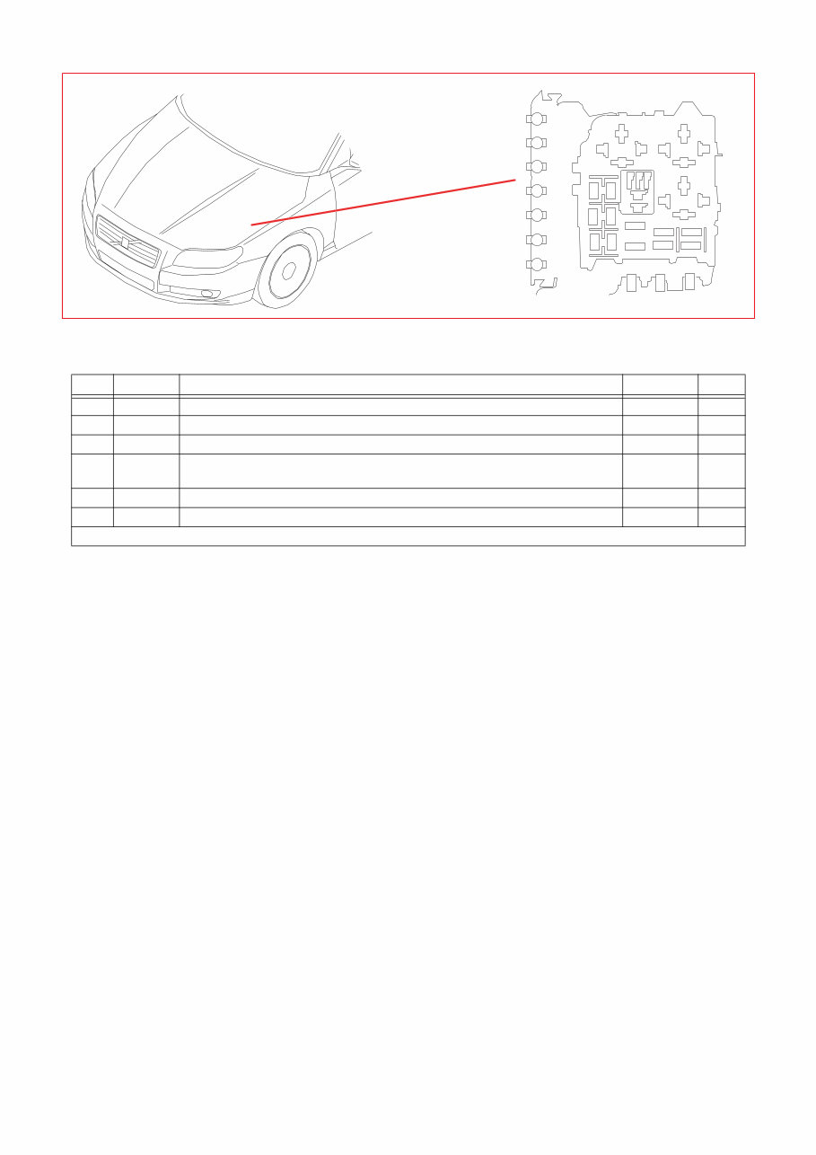
Fuses
Engine compartment electrical center F1-F7
15/31 Engine compartment electrical center
No. No. Fuse function via A
F1 11A/1 Main fuse for fuses in CEM 4/56 60
F2 11A/2 Main fuse for fuses in CEM 4/56 60
F3 11A/3 11D/A1-11D/A11 Fuses in cargo compartment 15/32 - 60
F4 11A/4 11D/B1-11D/B8 Fuses in cargo compartment 15/32
11D/C1-11D/C7 Fuses in cargo compartment 15/32
-
-
60
F5 11A/5 11D/D1-11D/D7 Fuses in cargo compartment 15/32 - 50
F7 11A/7 9/42 PTC element - 100
continues
You're Reading a Preview
What's Included?
Fast Download Speeds
Offline Viewing
Access Contents & Bookmarks
Full Search Facility
Print one or all pages of your manual
$28.99
Viewed 60 Times Today


Secure transaction
What's Included?
Fast Download Speeds
Offline Viewing
Access Contents & Bookmarks
Full Search Facility
Print one or all pages of your manual
$28.99
This manual provides the complete wiring diagrams for the VOLVO S80 (07-) car, covering production model years 2007 and onwards.
- Fuses
- Relays
- Ground connections
- Control modules
- Fuel system
- Cooling system
- Engine controls
- Alternator and voltage regulator
- Starting system
- Lighting
- Additional electrical equipment
- Wiring and fuses
- Instruments
- Transmission
- Parking brake
- Brake system
- Steering
- Shock absorbers
- Doors and openings
- Exterior decorative elements
- Interior equipment
- Climate control system
- Internal equipment
Model Specification: VOLVO S80 (07-)
Model Year: 2007
Language: English
Total Pages: 373
File Format: PDF (.PDF)
Requirements: Adobe Reader
ZOOM IN/OUT: YES
Compatible: All Versions of Windows & Mac
All pages are printable, allowing you to easily take the manual with you into the garage or workshop. By following the step-by-step instructions, both professional mechanics and DIY enthusiasts can save money by performing their own repairs.


