WIRING DIAGRAM 2014
VOLVO S60 (11-), V60
TP 39262202 Structure week 13w20
© Volvo Car Corporation
Vehicles with SRS (Airbag)/SIPS bag/IC
(Inflatable curtain)
Warning!
Extra caution must be exercised when working on vehicles equipped with SRS/SIPS bag/IC
in order to avoid:
1. Personal injuries when performing repair work.
2. Damage or malfunction of the SRS/SIPS bag/IC system.
Work involving the SRS/SIPS bag/IC systems or other components in the vehicle that may
affect the SRS/SIPS bag/IC systems must always be performed by an authorized Volvo
workshop.
In case of doubt, consult the SRS and SIPS bag/IC service manual.
Is the vehicle equipped with SRS/SIPS bag/IC?
Vehicles with SRS are most easily recognized by the letters SRS in the center of the steering
wheel. If the vehicle also has a passenger side airbag, the letters SRS are stamped on the
dashboard above the glove compartment. SRS vehicles from 1993 and onward also have
explosive seat belt tensioners. SIPS bags are only installed on SRS vehicles from 1995 and
onward. SIPS bag decals are located on the windshield and seat compartment. Vehicles with
IC can be recognized by the letters IC on the C/D panel (4 door) or the B panel (5 door).
General recommendations
• Be especially careful when working on or around SRS, SIPS, and IC components.
• Make sure that no wires are pinched, frayed, or pierced.
• Never fit accessories by the sensors.
• Where applicable, work on the steering wheel, steering shaft, or steering gear must be done
in accordance with the methods in the SRS section of VIDA.
• Certain components of the aforementioned systems must be grounded while working. Read
the appropriate sections in VIDA.
• Do not install any accessories in the areas between the A and B-posts, the B and C-posts,
and the C and D-posts.
Test terminal
Fuse in cargo compartment auxiliary fuse box
Changes introduced up to and including structure week 13w20
Any changes made to the vehicle after this date are not included in the manual. If necessary,
refer to service bulletins.
Volvo models are sold in versions adapted for different markets. These adaptations depend
on factors such as legal requirements, taxation, and market demands.
This manual may therefore include illustrations and text that do not apply to the vehicles in
your country.
Ordering :
Electronic Wiring Diagrams (EWD) can be ordered from the Technical Information Shop (TIS)
We retain the right to make modifications.
TP39262202 S60 (11-), V60 2014 © Volvo Car Corporation 2013 3
Explanations & Abbreviations ........................................ 6
How to use the wiring diagrams 1:2 ............................... 7
Electrical distribution
Overview without Start/stop function ............................ 9
Overview with Start/stop function ................................ 10
Overview, Distribution box in engine compartment ..... 11
Overview, Distribution box in passenger compartment 12
Overview, Distribution box in cargo compartment ....... 13
Fuses
Distribution box in engine compartment F1 - F7 ........... 14
Distribution box in engine compartment F8 - F23 ......... 15
Distribution box in engine compartment F27 - F36 ....... 16
Distribution box in engine compartment F37 - F38 ....... 17
Distribution box in engine compartment F39 - F44 ....... 18
Central Electronic Module (CEM) F1 - F8 ..................... 19
Central Electronic Module (CEM) F9 - F19 ................... 20
Central Electronic Module (CEM) F20 - F24 ................. 21
Distribution box in passenger compartment F1 - F17... 22
Distribution box in passenger compartment F18 - F30. 23
Distribution box in engine compartment, cold zone ...... 24
Distribution box in cargo compartment FA1 - FA11 ...... 25
Battery PF1 - PF2 ......................................................... 26
Relays
Relays in the engine compartment .............................. 27
Relays in the engine compartment .............................. 28
Relays in passenger and cargo compartments ........... 29
Ground connections
Overview ...................................................................... 30
31/1 - 31/7 .................................................................... 31
31/10 - 31/15 continues ............................................... 32
31/15 - 31/67 ................................................................ 33
31/68 - 31/89 ................................................................ 34
31/90 - 31/130 .............................................................. 35
31/131 - 31/TRM .......................................................... 36
Control modules
Overview locations ....................................................... 37
Overview designations ................................................. 38
Central Electronic Module (CEM) 1:3 .......................... 39
Data communication, High speed CAN 1:2 ................. 42
Data communication intermediate speed CAN, LHD ... 44
Data communication intermediate speed CAN, RHD .. 45
Data communication Local CAN .................................. 46
Data communication Extended CAN ........................... 47
Data communication, LIN 1:2 ....................................... 48
Data communication MOST ......................................... 50
Steering Wheel Module (SWM) ................................... 51
Group 26 Cooling system
Cooling fan, 4-Cyl. Turbo ............................................. 52
Cooling fan, 4-Cyl. Diesel ............................................ 53
Cooling fan, 5-Cyl. Diesel ............................................ 54
Cooling fan, 5-Cyl. Turbo ............................................. 55
Cooling fan, 6-Cyl . ....................................................... 56
Group 27 Engine controls
Cruise control 4-Cyl. Turbo 1.6l .................................... 57
Cruise control 4-Cyl. Turbo 2.0l .................................... 58
Cruise control 4-Cyl. Diesel .......................................... 59
Cruise control 5-Cyl. Diesel .......................................... 60
Cruise control 5-Cyl. Turbo & 6-Cyl . ............................. 61
Start-/Stop function 4-Cyl. Turbo .................................. 62
Start-/Stop function 4-Cyl. Diesel .................................. 63
Start-/Stop function 5-Cyl. Diesel .................................. 64
Start-/Stop function 5-Cyl. Turbo .................................. 65
Group 28 Ignition and control system
Engine management system 4-Cyl. 1.6l Turbo 1:2 ...... 66
Engine management system 4-Cyl. 2.0l Turbo 1:2 ...... 68
Engine management system, 5-Cyl. Turbo 1:2 ............ 70
Engine management system, 6-Cyl. Turbo 1:2 ............ 72
Engine management system, 4-Cyl. Diesel 1:3 ........... 74
Engine management system, 5-Cyl. Diesel 1:3 ........... 77
Emission control 4-Cyl. 1.6l Turbo ............................... 80
Emission control 4-Cyl. 2.0l Turbo ............................... 81
Emission control 5-Cyl. Turbo ...................................... 82
Emission control 6-Cyl . ............................................... 83
Table of Contents 1:3
TP39262202 S60 (11-), V60 2014 © Volvo Car Corporation 2013 4
Group 32 Alternator and voltage regulator
Power supply 4-Cyl. without Start/Stop ....................... 84
Power supply 5-Cyl. & 6-Cyl. without Start/Stop .......... 85
Power supply 4-Cyl. & 5-Cyl. with Start/Stop ............... 86
Group 33 Starting system
Starting system 4-Cyl ................................................... 87
Starting system, 5-Cyl. & 6-Cyl .................................... 88
Starting system, 5-Cyl. Diesel ...................................... 89
Group 35 Lighting
High and low beam ...................................................... 90
High and low beam (Dual Xenon) ................................ 91
Beam length adjustment, manual ................................ 92
Running/Parking light, Tail lights S60 .......................... 93
Running/Parking light, Tail lights V60 .......................... 94
Fog lights S60 .............................................................. 95
Fog lights V60 .............................................................. 96
Brake lights S60 ........................................................... 97
Brake lights V60 ........................................................... 98
Reversing lights S60 .................................................... 99
Reversing lights V60 .................................................. 100
Follow-me-home lighting LHD ................................... 101
Follow-me-home lighting RHD ................................... 102
Interior lighting, LHD 1:2 ............................................ 103
Interior lighting, RHD 1:2 ........................................... 105
Active headlight ......................................................... 107
Auxiliary lights ............................................................ 108
Group 36 Additional electrical equipment
Rain sensor ................................................................ 109
Direction indicator and hazard warning flashers
LHD S60 .................................................................... 110
Direction indicator and hazard warning flashers
LHD V60 .................................................................... 111
Direction indicator and hazard warning flashers
RHD S60 .................................................................... 112
Direction indicator and hazard warning flashers
RHD V60 .................................................................... 113
Window washer and windshield wiper ....................... 114
Washer headlights ..................................................... 115
Wiper rear window V60 .............................................. 116
Horn ...................................................................... 117
Keyless vehicle 1:2 .................................................... 118
Anti-theft alarm .......................................................... 120
Parking assistance ..................................................... 121
Collision warning with power brake booster .............. 122
Tire pressure monitoring system (TPMS) .................. 123
Alcohol lock ................................................................ 124
Group 37 Wiring and fuses
Diagnostics system .................................................... 125
Outlet 12V .................................................................. 126
Outlet 12V, V60 .......................................................... 127
Cable harness towbar/tow hitch 13-pin S60 .............. 128
Cable harness towbar/tow hitch 13-pin V60 .............. 129
Group 38 Instruments
Seat belt reminder ...................................................... 130
Driver information system .......................................... 131
Group 39 Other
Audio Premium 1:3 .................................................... 132
Audio 1:2 .................................................................... 135
Cellular phone 1:2 ...................................................... 137
DAB Radio ................................................................. 139
Multimedia monitor with DVD, Dual Screen (RSE) .... 140
TV receiver / TV control module S60 ......................... 141
TV receiver / TV control module V60 ......................... 142
Bluetooth Handsfree .................................................. 143
Navigation system and Traffic information, portable .. 144
Satellite radio ............................................................. 145
Parking camera rear .................................................. 146
Parking camera rear .................................................. 147
Parking camera wide angle front ............................... 148
Sensus Connected Touch .......................................... 149
Group 43 Transmission
Transmission M66 ...................................................... 150
Automatic transmission AWF21 ................................. 151
Automatic transmission MPS6 ................................... 152
Differential Electronic Module (DEM) ......................... 153
Group 55 Parking brake
Electric parking brake ................................................ 154
Group 59 Brake system
Brake control system & DSTC ................................... 155
Group 64 Steering
Speed dependent power steering .............................. 156
Group 76 Shock absorbers
Four-C ...................................................................... 157
Table of Contents 2:3
TP39262202 S60 (11-), V60 2014 © Volvo Car Corporation 2013 5
Group 83 Doors and openings
Central locking front doors LHD ................................. 158
Central locking front doors RHD ................................ 159
Central locking rear doors .......................................... 160
Central locking tailgate S60 ....................................... 161
Central locking tailgate V60 ....................................... 162
Central locking fuel filler flap ...................................... 163
Signal receiver central locking ................................... 164
Power windows front doors LHD ............................... 165
Power windows front doors RHD ............................... 166
Power windows rear doors ........................................ 167
Power sunroof ............................................................ 168
Group 84 Exterior decorative elements, etc.
Power door mirrors LHD ............................................ 169
Power door mirrors RHD ........................................... 170
Heated door mirrors LHD ........................................... 171
Heated door mirrors RHD .......................................... 172
Blind spot information system LHD 1:2 ...................... 173
Blind spot information system LHD 2:2 ...................... 174
Blind spot information system RHD 1:2 ..................... 175
Blind spot information system RHD 2:2 ..................... 176
Heated windscreen LHD ............................................ 177
Heated windscreen RHD ........................................... 178
Heated rear window ................................................... 179
Group 85 Interior equipment
Power driver’s seat with memory function, LHD ........ 180
Power driver’s seat with memory function, RHD ....... 181
Power passenger seat, LHD ...................................... 182
Power passenger seat, RHD ..................................... 183
Heated steering wheel ............................................... 184
Heated front seats with fans ...................................... 185
Heated front seats without fans ................................. 186
Heated rear seat ........................................................ 187
Group 87 Climate control system
Climate control system, 4-Cyl. 1:2 ............................. 188
Climate control system 4-Cyl. Diesel 1:2 ................... 190
Climate control system 5-Cyl. & 6-Cyl. 1:2 ................ 192
Climate control system PTC-elements ...................... 194
Parking heater, auxiliary heater ................................. 195
Parking heater, remote start ...................................... 196
Group 88 Internal equipment
Supplemental restraint system 1:2 ............................ 197
Rear-view mirror with automatic dimming .................. 199
Remote control opener garage door .......................... 200
Power folding headrest .............................................. 201
Group 89 Body other
Radiator masking blind .............................................. 202
Connectors .............................................. 203
Branching points .................................... 238
Cable harness routing in vehicle
Harness engine 4-Cyl. Turbo ...................................... 259
Harness engine, 6-Cyl. Turbo ..................................... 259
Harness engine, 2.0L Diesel ....................................... 260
Harness engine, 2.4L Diesel ....................................... 260
Engine compartment harness LHD ............................. 261
Engine compartment harness RHD ............................ 262
Harness dashboard, LHD ........................................... 263
Harness Dashboard, RHD .......................................... 264
Harness Floor, LHD S60 ............................................. 265
Harness Floor, RHD S60 ............................................ 266
Floor Harness, LHD V60 ............................................. 267
Harness Floor, RHD V60 ............................................ 268
Harness infotainment, LHD S60 ................................. 269
Harness infotainment, RHD S60 ................................. 270
Harness infotainment, LHD V60 ................................. 271
Harness infotainment, RHD V60 ................................. 272
Roof harness, S60 ...................................................... 273
Roof harness V60 ....................................................... 273
Center console harness .............................................. 274
Tunnel harness ........................................................... 274
Harness front door, left ............................................... 275
Harness front door, right ............................................. 275
Harness rear door, left ................................................ 276
Harness rear door, right .............................................. 276
Trunk lid/tailgate harness, S60 ................................... 277
Trunk lid/tailgate harness, V60 ................................... 277
Harnesses rear axle .................................................... 278
Component illustrations ......................... 279
Index 1:2 ................................................... 335
List of components 1:6 ........................... 337
Table of Contents 3:3
TP39262202 S60 (11-), V60 2014 © Volvo Car Corporation 2013 6
Explanations & Abbreviations
Groups
Group 26 = Cooling system
Group 27 = Engine controls
Group 28 = Ignition and control system
Group 32 = Alternator and voltage regulator
Group 33 = Starting system
Group 35 = Lighting
Group 36 = Additional electrical equipment
Group 37 = Wiring and fuses
Group 38 = Instruments
Group 39 = Other
Group 43 = Transmission
Group 55 = Parking brake
Group 59 = Brake system
Group 64 = Steering
Group 76 = Shock absorbers
Group 83 = Doors and openings
Group 84 = Exterior decorative elements, etc.
Group 85 = Interior equipment
Group 87 = Climate control system
Group 88 = Internal equipment
Group 89 = Body other
Designations ignition switch
X = Accessories (audio position)
S = Powered upon insertion of key
15 = The switch remains connected during
start
15l = Contact is broken while starting
30 = Constant power from the battery
50 = Start
Countries/Markets
A = Austria
AUS = Australia
B = Belgium
CDN = Canada
CH = Switzerland
D = Germany
DK = Denmark
E = Spain
EU/OS = Markets outside USA and Canada
FIN = Finland
GB = Great Britain
ISR = Israel
J = Japan
KOR = Korea
N = Norway
NL = Netherlands
S = Sweden
USA = United States of America
WEU = Western Europe
Other
ACC = Adaptive Cruise Control
Ag = Silver plated
Au = Gold plated
AUTO = Automatic transmission
BLIS = Blind Spot Information System
CAN = CAN communication
DPY = Display
ECC = Electronic climate control system
ETA = Throttle unit
EXC = Exclusive
GDL = Gas discharge lamp
HS = High speed data bus
KEYLESS = Keyless vehicle
IR = Infrared sensor
LIN = LIN communication
LH = Left-hand side
LHD = Left-hand drive
MAN = Manual transmission
MEMORY = Memory driver’s seat
MIRCAM = Parking camera in rear-view mirror
MS = Midspeed data bus
MMS = Mass Movement Sensor
PANROOF = Panoramic roof
PETROL = Gasoline
RH = Right-hand side
RHD = Right-hand drive
RTI = Road Traffic Information
SCR = Screened
SRS = Airbag
T = Turbo engine
W/O = Without
2WD = Two-wheel drive
4CYL, I4 = 4-cylinder engine
5CYL, I5 = 5-cylinder engine
6CYL, I6 = 6-cylinder engine
Colors
BK, SB = Black
BN = Brown
BU, BL = Blue
GN = Green
GY, GR = Gray
LGN = Light Green
NL = Natural
OG, OR = Orange
PK, P = Pink
RD, R = Red
VT, VO = Violet
WH, W = White
YE, Y = Yellow
TP39262202 S60 (11-), V60 2014 © Volvo Car Corporation 2013 7
The descriptions below apply in general
to all wiring diagram manuals, although
not all sections are necessarily con-
tained in this manual.
The systems are shown in non-active
status.i.e. with "key removed" and when
the doors, hatches and hood are closed.
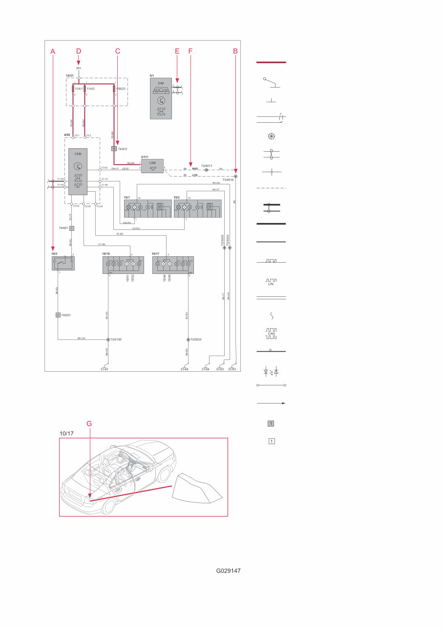
How to use the wiring diagrams 1:2
A. Component designation
Every component has a component designation that
consists of two parts.
The first part is a type number that describes the
type of component in question, for example 3/xx.
The second part of the designation is a serial num-
ber, for example x/2.
Combined these give a component designation, for
example 3/2.
At the end of the manual is a list of components,
where, with the help of the component designation,
you can read off the name of the component, for
example, 3/2 = light switch.
List of type numbers
The list shows which type of component that respec-
tive type numbers refer to, for example, 3/x = switch,
6/x = electric motor, etc.
1 Battery
2 Relay
3 Switch
4 Control module
5 Driver Information Module
6 Electric motor
7 Sensor
8 Actuator
9 Heating element
10 Light
11 Fuse
15 Electrical distribution rail/box
16 Audio
17 Service/diagnostics
18 Contact reel
19 Meter
20 Ignition component/shunt
27 Optics
31 Ground connection
73 Branching point
74 Connector
B. Branching points
The wiring diagrams contain numbered branching
points, for example 73/5035.
This manual contains a section with a list of branch-
ing points. This list shows all the components which
are connected to each branching point.
The location of the branching points is shown in the
"Cable harness routing in vehicle" section.
C. Connectors
Connectors provide a bridge between two cable har-
nesses and are described in the "Connectors" sec-
tion.
D. Electrical distribution
Operation of the fuses and relays is shown in the
"Electrical distribution" section.
E. Data communication
Today’s cars contain CAN, LIN and MOST networks
that transfer information. Connections to these net-
works are not shown in their entirety in the respec-
tive wiring diagram. Complete information on CAN,
LIN and MOST communication is found in the sec-
tion "Control modules".
F. Abbreviations
A number of different abbreviations are used in the
manual. These are explained in the section "Abbre-
viations".
G. Component location
There is a section at the end of the manual in which
the appearance and location of components is
described in numerical order.
TP39262202 S60 (11-), V60 2014 © Volvo Car Corporation 2013 8
How to use the wiring diagrams 2:2
Explanation of symbols
= System voltage
= Ground connection via wiring
= Ground connection in
component/chassis
= Screened wire
= Branching point
= Twisted cable
= Electrical connection
= Variant
= CAN communication
= CAN high data signal (CAN H)
= CAN low data signal (CAN L)
= LIN communication
= LIN communication
= DIN cable, coaxial cable, etc.
= Data communication
= CAN communication
= MOST communication
= MOST communication
= Connection with distribution box
= Further connection to...
= Connector between cable
harnesses
= Connector connected in
component
TP39262202 S60 (11-), V60 2014 © Volvo Car Corporation 2013 9
15/36
R1
2/88
2
1
3
5
R4
2/193
2
1
3
5
11D/A6
2 1
11D/A5
2 1
11D/A3
2 1
11D/A2
2 1
11D/A1
2 1
11D/A4
2 1
11D/A11
2 1
11D/A12
2 1
2
1
3
5
2/82
15/32
RA2
2
1
3
5
A
RA1
RD-GN
RD-GN
RD-GN
RD-VT
RD-VT
73/5075
2/16
74/504B
2
R7
2/31
2
1
3
5
11A/3
1 2
11A/2
1 2
11A/1
1 2
11A/4
1 2
11A/5
1 2
11B/17
RD
1
2
1 2
15/31
11B/27
C1:63
C1:13
C5:1
C5:2
C2:5
C1:9
A31W051
GY-BK
RD-BU
RD-BK
GN-VT
RD-GN
RD-BN
RD-GY
RD-GN
74/504
14
VT-GN
VT-GN
RD
BU
RD
RD
CAN
CEM
4/56
LIN
1
2
1
2
1
2
1
2
1
2
1 2
1 2
1 2
1 2
F17
F18
F19
F20
1 2
F1
F2
F3
F4
F5
F6
1
2
11C/21
1
2
11C/24
1
2
11C/28
12V
BK
31/3
1/1
RD
2
1
PF1
RD-VT
RD-VT
RD-VT
7/240
BMS
LIN
I
U
73/3137
73/3136
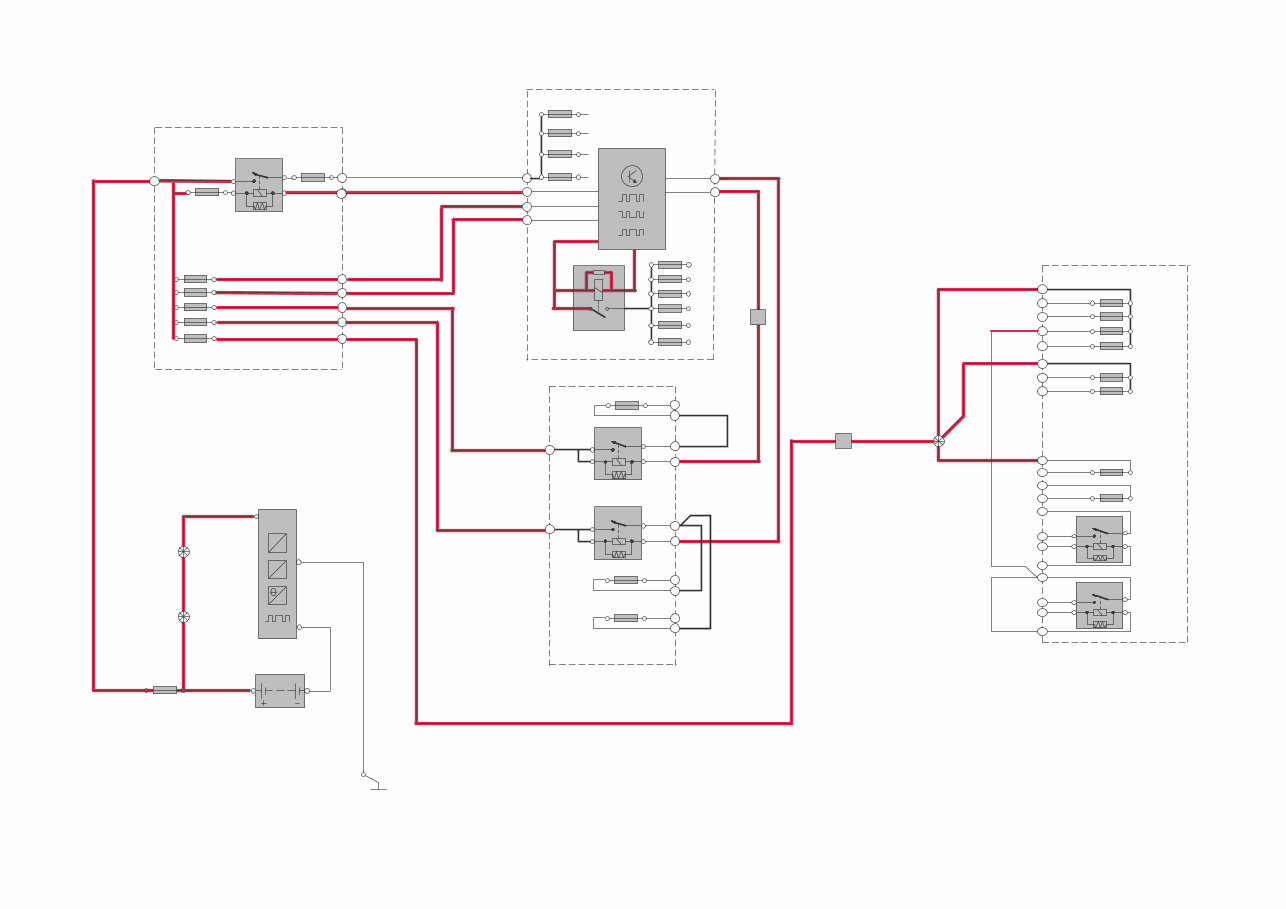
1
Electrical distribution
Overview without Start/stop function
TP39262202 S60 (11-), V60 2014 © Volvo Car Corporation 2013 10
15/36
R1
2/88
2
1
3
5
R4
2/193
2
1
3
5
11D/A6
2 1
11D/A5
2 1
11D/A3
2 1
11D/A2
2 1
11D/A1
2 1
11D/A4
2 1
11D/A11
2 1
11D/A12
2 1
2
1
3
5
2/82
15/32
RA2
2
1
3
5
A
RA1
RD-GN
RD-GN
RD-GN
RD-VT
RD-VT
73/5075
2/16
74/504B
R7
2/31
11A/3
1
2
11A/2
1
2
11A/1
1
2
11A/4
1
2
11A/5
1
2
11B/17
RD
1
2
1
2
15/31
11B/27
CAN
CEM
4/56
C1:63
C1:13
C5:1
C5:2
LIN
C2:5
C2:17
C1:9
1 2
1 2
GY-BK
RD-BU
RD-BK
GN-VT
RD-GN
RD-BN
RD-GY
RD-GN
74/504
14
VT-GN
RD
RD
RD
RD
2 1
2 1
2 1
2 1
2 1
2 1
11A/8
2 1
2
1
3
5
15/37
R2
2/246
2
1
2
1
2
1
3
5
2
1
3
5
11A/7
2
1
2
1
11B/12
2
1
2
1
2
1
R1
2/166
11A/6
MF1
F10
11A/2
MF2
M11
11A/1
11A/4
11A/5
11A/3
11A/9
12V
BK
31/131
1/2
RD
74/301
27
74/504
19
74/316
4
RD
RD
RD
RD
12V
31/3
1/1
RD
2
1
PF1
2
1
PF4
2
BK
PF1
RD-VT
RD-VT
RD-VT
7/240
BMS
LIN
I
U
73/3137
73/3136
1
MAN
73/3162
AUTO
RD
RD
RD
RD
1
2
11B/34
A31W052
1 2
1
2
1 2
1
2
F17
F18
F19
F20
1 2
11C/21
11C/28
11C/24
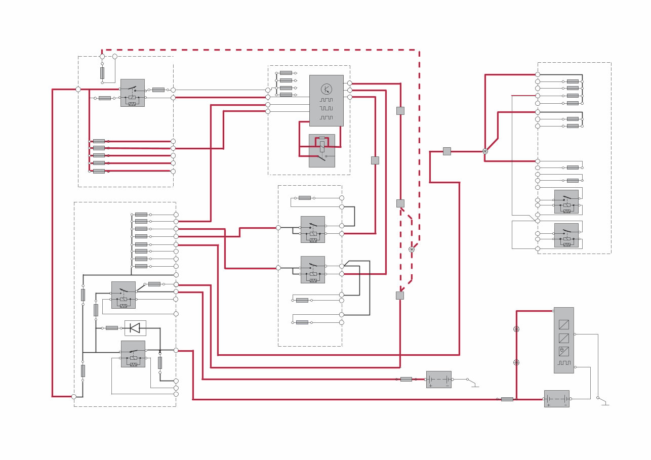
Electrical distribution
Overview with Start/stop function
You're Reading a Preview
What's Included?
Lifetime Access
Access PDF Contents & Bookmarks
Print one or all pages of your manual